Page is loading ...

WARNING
Installation must be done by a contractor qualified
in the installation and service of gas-fired heating
equipment or your gas supplier.
Improper installation, adjustment, alteration, service
or maintenance can result in death, injury or property
damage. Read the Installation, Operation and Service
Manual thoroughly before installing or servicing
this equipment.
Installer
Please take the time to read and understand
these instructions prior to any installation.
Installer must give a copy of this manual to the owner.
Owner
Keep this manual in a safe place in order to provide
your serviceman with necessary information.
CRV-B-2
CRV-B-4
CRV-B-6
CRV-B-8
CRV-B-9
CRV-B-10
CRV-B-12
CRV-B-12A
P/N 127102NA Rev. F 05/06
CoRayVac
®
Custom-Engineered,
Low-Intensity Infrared
Heating Systems
Installation, Operation &
Service Manual
WARNING
FOR YOUR SAFETY
If you smell gas:
1. Open windows.
2. DO NOT try to light any appliance.
3. DO NOT use electrical switches.
4. DO NOT use any telephone in
your building.
5. Leave the building.
6. Immediately call your local gas
supplier after leaving the building.
Follow the gas suppliers
instructions.
7. If you cannot reach your gas
supplier, call the Fire Department.
Fire Hazard
Do not store or use gasoline or other
flammable vapors and liquids in the
vicinity of this or any other appliance.
Some objects will catch fire or explode
when placed close to heater.
Failure to follow these instructions can
result in death, injury or property
damage.
© Copyright 2006 Roberts-Gordon
Quality in Any Language™
Roberts-Gordon, LLC
1250 William Street
P.O . B o x 4 4
Buffalo, New York 14240-0044
Telephone: 716.852.4400
Fax: 716.852.0854
Toll Free: 800.828.7450
www.rg-inc.com


© 2006
ROBERTS GORDON, LLC
All rights reserved. No part of this work covered by the copyrights herein may be reproduced
or copied in any form or by any means - graphic, electronic, or mechanical, including
photocopying, recording, taping or information storage and retrieval systems - without the
written permission of Roberts-Gordon, LLC.
TABLE OF CONTENTS
SECTION 1: Heater Safety......................................................1
1.1 Manpower Requirements .............................................1
SECTION 2: Installer Responsibility ..................................... 2
2.1 Wall Tag ....................................................................... 2
2.2 Corrosive Chemicals.................................................... 2
2.3 National Standards and Applicable Codes .................. 2
SECTION 3: Critical Considerations......................................3
3.1 Required Clearances to Combustibles......................... 3
SECTION 4: National Standards and Applicable Codes ..... 7
4.1 Gas Codes................................................................... 7
4.2 Aircraft Hangars ........................................................... 7
4.3 Public Garages ............................................................ 7
4.4 Electrical ...................................................................... 7
4.5 Venting......................................................................... 7
4.6 High Altitude ................................................................ 7
SECTION 5: Major Components ............................................ 8
5.1 Standard Parts List .................................................... 11
SECTION 6: Design Requirements...................................... 13
SECTION 7: Heater Installation............................................ 15
7.1 Tube Installation ........................................................16
7.2 Coupling and Tube Assembly....................................16
7.3 Elbow Package Configuration..................................... 17
7.4 Reflector Installation .................................................. 18
7.5 Burner Installation...................................................... 20
SECTION 8: Optional Heater Accessories.......................... 21
8.1 Tee Installation ..........................................................21
8.2 Reflector Joint............................................................ 21
8.3 Reflector Side Extension............................................23
8.4 Universal Shield.........................................................24
8.5 Barrier Shield............................................................. 24
8.6 Two-Foot Decorative Grille Installation....................... 25
8.7 One-Foot Decorative Grille Installation ...................... 26
8.8 Protective Grille Installation........................................29
8.9 Classic Cast-Iron Components ................................. 30
SECTION 9: Pump Installation and Venting ....................... 31
9.1 Pump Installation ....................................................... 31
9.2 General Venting Requirements Model EP-100,
EP-200 and EP-300 Series Pumps ............................32
9.3 Horizontal Venting 4" (10 cm) Pipe ............................34
SECTION 10: Outside Air Supply.........................................37
10.1 Pressurized .............................................................. 37
10.2 Non-Pressurized ...................................................... 37
10.3 Outside Air Blower Internal Wiring ........................... 38
SECTION 11: Gas Piping ...................................................... 41
SECTION 12: Control Methods ............................................ 42
12.1 ROBERTS GORDON
®
System Control................... 42
12.2 ROBERTS GORDON
®
ULTRAVAC
TM
..................... 42
12.3 SPST Transformer Relay (P/N 90417600) ............... 42
12.4 DPST Transformer Relay (P/N 90436300)............... 42
SECTION 13: Starting The System...................................... 49
13.1 Checking the Gas Line ............................................ 49
13.2 Checking the Electrical System ............................... 49
13.3 Starting the System ................................................. 49
13.4 Setting the Vacuum.................................................. 49
SECTION 14: Operation and Maintenance.......................... 51
14.1 Sequence of Operation............................................ 51
14.2 To Shut Off Heater................................................... 51
14.3 To Start Heater ........................................................ 51
14.4 Pre-Season Maintenance and Annual Inspection.... 51
14.5 Maintenance Checklist............................................. 52
SECTION 15: Troubleshooting............................................. 55
15.1 Troubleshooting Flow Chart ..................................... 55
SECTION 16: Replacement Parts ........................................ 57
SECTION 17: General Specifications.................................. 58
17.1 Material Specification ............................................... 58
17.2 Heater Specifications ............................................... 58
17.3 Suspension Specifications ....................................... 58
17.4 Controls Specifications............................................. 58
SECTION 18: The ROBERTS GORDON
®
CORAYVAC
®
Limited Warranty............................................ 61
Printed in U.S.A.


TABLE OF FIGURES
Figure 1: Standard Reflector ..................................................... 4
Figure 2: One Side Reflector..................................................... 4
Figure 3: Two Side Reflectors ...................................................4
Figure 4: Universal Shield, Position 1 .......................................5
Figure 5: Universal Shield, Position 2 .......................................5
Figure 6: Universal Shield, Position 3 .......................................5
Figure 7: 2-Foot Deco Grille......................................................6
Figure 8: Barrier Shield ............................................................. 6
Figure 9: 1-Foot Deco Grille ...................................................... 6
Figure 10: Major Component Descriptions................................ 8
Figure 11: Heater Assembly Overview ................................... 14
Figure 12: Critical Hanger Placement ..................................... 15
Figure 13: Reflector Joint Detail .............................................. 22
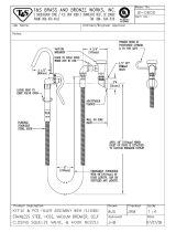
Figure 14: EP-200 Condensate Valve Assembly..................... 31
Figure 15: Vertical Venting Configuration ................................ 33
Figure 16: EP-100 Horizontal Venting Configurations ............. 34
Figure 17: EP-200 Series Horizontal
Venting Configurations...........................................35
Figure 18: EP-300 Series Horizontal
Venting Configurations...........................................36
Figure 19: Duct Sizing ............................................................ 37
Figure 20: Outside Air Blower Internal Wiring Diagram...........38
Figure 21: Filter Housing Assembly ........................................38
Figure 22: Air Supply Blower Support..................................... 39
Figure 23: Pressurized Outside Air Supply..............................39
Figure 24: Non-Pressurized Outside Air Supply...................... 40
Figure 25: Gas Connection with Flexible Gas Hose................ 41
Figure 26: One Zone Operation without Control Panel ........... 43
Figure 27: One Zone Operation (with Outside Air Blower)
without Control Panel.............................................44
Figure 28: Two Zone Operation without Control Panel............45
Figure 29: General System Wiring ..........................................46
Figure 30: External Wiring Diagram EP-100 and EP-201
120 V 1 Ø Pump ....................................................46
Figure 31: External Wiring Diagram EP-301
120 V 1 Ø Pump ....................................................47
Figure 32: External Wiring Diagram EP-203 or
EP-303 208 V - 230 V (or 460 V) 3 Ø Pump .......... 47
Figure 33: Burner Internal Wiring............................................ 48
Figure 34: Burner Internal Ladder Diagram ............................48
Figure 35: Vacuum Reading....................................................50


SECTION 1: HEATER SAFETY
1
SECTION 1: HEATER SAFETY
Your Safety is Important to Us!
This symbol is used throughout
the manual to notify you of
possible fire, electrical or burn
hazards. Please pay special
attention when reading and
following the warnings in these
sections.
Installation, service and annual inspection of heater
must be done by a contractor qualified in the
installation and service of gas-fired heating
equipment.
Read this manual carefully before installation,
operation or service of this equipment.
This heater is designed for heating nonresidential
indoor spaces. Do not install in residential spaces.
These instructions, the layout drawing, local codes
and ordinances, and applicable standards that apply
to gas piping, electrical wiring, venting, etc. must be
thoroughly understood before proceeding with the
installation.
Thin sheet metal parts, the aluminum reflector
portion of the heater and the various venting
components, have sharp edges. To prevent injury,
the use of work gloves is recommended. The use of
gloves will also prevent the transfer of body oils from
the hands to the surface of the reflector.
Before installation, check that the local distribution
conditions, nature of gas and pressure, and
adjustment of the appliance are compatible.
1.1 Manpower Requirements
To prevent personal injury and damage to the heater,
two persons will be required for installation.

CRV-SERIES INSTALLATION, OPERATION AND SERVICE MANUAL
2
SECTION 2: INSTALLER RESPONSIBILITY
The installer is responsible for the following:
• To ensure the system is designed in accordance
with the parameters of the CRV-Series
Design
Manual (P/N 127500NA).
• To install the heater, as well as the gas and
electrical supplies, in accordance with applicable
specifications and codes. Roberts-Gordon
recommends the installer contact a local Building
Inspector or Fire Marshal for guidance.
• To use the information given in a layout drawing
and in the manual together with the cited codes
and regulations to perform the installation.
• To install the heater in accordance with the
clearances to combustibles requirements.
• To furnish all needed materials not furnished as
standard equipment.
• To plan location of supports.
• To provide access to burners on all sides for
servicing or burner removal.
• To provide the owner with a copy of this
Installation, Operation and Service Manual.
• To never use heater as a support for ladder or
other access equipment and to never hang or
suspend anything from heater.
• To ensure there is adequate air circulation around
the heater and to supply air for combustion,
ventilation and distribution in accordance with
local codes.
• To safely and adequately install heater using
materials with a minimal working load of 75 lb
(33 kg).
2.1 Wall Tag
A laminated wall tag is available for the heater as a
permanent reminder of the safety instructions and
the importance of the required clearances to
combustibles. Please contact Roberts-Gordon or
your ROBERTS GORDON
®
independent distributor
to obtain the wall tag. Affix the tag by peeling off the
backing of the adhesive strips on the rear surface
and position the tag on a wall near the CRV-Series
heater (e.g. thermostat or controller).
A copy of the wall tag (P/N 91037912) is illustrated on
the back cover. For an immediate solution, you may
affix this copy on the wall near the heater.
Know your model number and installed configuration.
Model number and installed configuration are found
on the burner and in the Installation, Operation and
Service Manual. See Page 4, Figure 1 through Page
6, Figure 9. Write the proper clearance dimensions in
permanent ink according to your model number and
configuration in the open spaces on the tag.
2.2 Corrosive Chemicals
Roberts-Gordon cannot be responsible for ensuring
that all appropriate safety measures are undertaken
prior to installation; this is entirely the responsibility of
the installer. It is essential that the contractor, the
sub-contractor, or the owner identifies the presence
of combustible materials, corrosive chemicals or
halogenated hydrocarbons* anywhere in the
premises.
* Halogenated Hydrocarbons are a family of chemical
compounds characterized by the presence of halogen elements
(fluorine, chlorine, bromine, etc.). These compounds are
frequently used in refrigerants, cleaning agents, solvents, etc. If
these compounds enter the air supply of the burner, the life span
of the heater components will be greatly reduced. An outside air
supply must be provided to the burners whenever the presence
of these compounds is suspected. Warranty will be invalid if the
heater is exposed to halogenated hydrocarbons.
2.3 National Standards and Applicable Codes
All appliances must be installed in accordance with
the latest revision of the applicable standards and
national codes. This refers also to the electric, gas
and venting installation. Note: Additional standards
for installations in public garages, aircraft hangars,
etc. may be applicable.
CAUTION
Do not use heater in an area containing corrosive
chemicals.
Avoid the use of corrosive chemicals to ensure a
longer life of the burner, tubing and other parts.
Failure to follow these instructions can result in
property damage.

SECTION 3: CRITICAL C ONSIDERATIONS
3
SECTION 3: CRITICAL CONSIDERATIONS
3.1 Required Clearances to Combustibles
Clearances are the required distances that
combustible objects must be away from the heater to
prevent serious fire hazards. Combustibles are
materials that may catch fire and include common
items such as wood, paper, rubber, fabric, etc.
Maintain clearances to combustibles at all times
for safety.
Clearances for all heater models are located on the
burner of the heater and on Page 4, Figure 1 through
Page 6, Figure 9 in this manual. Check the
clearances on each burner for the model heater
being installed to make sure the product is suitable
for your application and the clearances are
maintained. Read and follow the safety guidelines
below:
• Keep gasoline or other combustible materials
including flammable objects, liquids, dust or
vapors away from this heater or any other
appliance.
• Maintain clearances from heat sensitive material,
equipment and workstations.
• Maintain clearances from vehicles parked below
the heater.
• Maintain clearances from swinging and overhead
doors, overhead cranes, vehicle lifts, partitions,
storage racks, hoists, building construction, etc.
• In locations used for the storage of combustible
materials, signs must be posted to specify the
maximum permissible stacking height to maintain
required clearances from the heater to the
combustibles. Signs must be posted adjacent to
the heater thermostat. In the absence of a
thermostat, signs must be posted in a
conspicuous location.
• Consult local Fire Marshal, Fire Insurance Carrier
or other authorities for approval of proposed
installation when there is a possibility of exposure
to combustible airborne materials or vapors.
• Hang heater in accordance to the minimum
suspension requirements on Page 15, Figure 12.
• If the radiant tubes must pass through the building
structure, be sure that adequate sleeving and fire
stop is installed to prevent scorching and/or fire
hazard.
WARNING
Fire Hazard
Some objects will catch fire or explode when placed
close to heater.
Keep all flammable objects, liquids and vapors the
required clearances to combustibles away from heater.
Failure to follow these instructions can result in death,
injury or property damage.

CRV-SERIES INSTALLATION, OPERATION AND SERVICE MANUAL
4
NOTE: 1. All dimensions are from the surfaces of all tubes, couplings, elbows, tees and crosses.
2. Clearances B, C and D can be reduced by 50% after 25' (7.5 m) of tubing downstream from
where the combustion chamber and the tube connect.
* Protective Grille clearances are the same as Standard Reflector.
.
FIGURE 1: STANDARD REFLECTOR
(inches) (centimeters)
Model ABCDABCD
CRV-B-2 4 20 48 20 11 51 122 51
CRV-B-4 4 20 48 20 11 51 122 51
CRV-B-6 4 20 48 20 11 51 122 51
CRV-B-8 4 20 48 20 11 51 122 51
CRV-B-9 4 36 60 36 11 92 153 92
CRV-B-10 4 366036119215392
CRV-B-12 4 36 60 36 11 92 153 92
CRV-B-12A 4 36 60 36 11 92 153 92
B
C
D
A
FIGURE 2: ONE SIDE REFLECTOR
(inches) (centimeters)
Model ABCDABCD
CRV-B-2 4 12 56 20 11 31 143 51
CRV-B-4 4 12 56 20 11 31 143 51
CRV-B-6 4 12 56 20 11 31 143 51
CRV-B-8 4 12 56 20 11 31 143 51
CRV-B-9 4 12 60 42 11 31 153 107
CRV-B-10 4 12 60 42 11 31 153 107
CRV-B-12 4 12 60 42 11 31 153 107
CRV-B-12A 4 12 60 42 11 31 153 107
A
B
C
D
FIGURE 3: TWO SIDE REFLECTORS
(inches) (centimeters)
Model ABCDABCD
CRV-B-2 4 12 56 12 11 31 143 31
CRV-B-4 4 12 56 12 11 31 143 31
CRV-B-6 4 12 56 12 11 31 143 31
CRV-B-8 4 12 56 12 11 31 143 31
CRV-B-9 4 12 60 12 11 31 153 31
CRV-B-10 4 12 60 12 11 31 153 31
CRV-B-12 4 12 60 12 11 31 153 31
CRV-B-12A 4 12 60 12 11 31 153 31
A
B
C
D

SECTION 3: CRITICAL C ONSIDERATIONS
5
NOTE: 1. All dimensions are from the surfaces of all tubes, couplings, elbows, tees and crosses.
2. Clearances B, C and D can be reduced by 50% after 25' (7.5 m) of tubing downstream from
where the combustion chamber and the tube connect.
FIGURE 4: UNIVERSAL SHIELD, POSITION 1
(inches) (centimeters)
Model ABCDABCD
CRV-B-2 4 12 12 12 11 31 31 31
CRV-B-4 4 12 12 12 11 31 31 31
CRV-B-6 4 12 12 12 11 31 31 31
CRV-B-8 4 12 12 12 11 31 31 31
CRV-B-9 8 18 24 18 21 46 61 46
CRV-B-10 8 18241821466146
CRV-B-12 8 18 24 18 21 46 61 46
CRV-B-12A 8 18241821466146
C
A
B
D
FIGURE 5: UNIVERSAL SHIELD, POSITION 2
(inches) (centimeters)
Model ABCDABCD
CRV-B-2 4 24 48 24 11 61 122 61
CRV-B-4 4 24 48 24 11 61 122 61
CRV-B-6 4 24 48 24 11 61 122 61
CRV-B-8 4 24 48 24 11 61 122 61
CRV-B-9 4 36 48 36 11 92 122 92
CRV-B-10 4 36 48 36 11 92 122 92
CRV-B-12 4 36 48 36 11 92 122 92
CRV-B-12A 4 36 48 36 11 92 122 92
C
A
B
D
FIGURE 6: UNIVERSAL SHIELD, POSITION 3
(inches) (centimeters)
Model ABCDABCD
CRV-B-2 4 12 56 30 11 31 143 77
CRV-B-4 4 12 56 30 11 31 143 77
CRV-B-6 4 12 56 30 11 31 143 77
CRV-B-8 4 12 56 30 11 31 143 77
CRV-B-9 8 12 60 42 21 31 153 107
CRV-B-10 8 12 60 42 21 31 153 107
CRV-B-12 8 12 60 42 21 31 153 107
CRV-B-12A 8 12 60 42 21 31 153 107
C
A
B
D

CRV-SERIES INSTALLATION, OPERATION AND SERVICE MANUAL
6
NOTE: 1. All dimensions are from the surfaces of all tubes, couplings, elbows, tees and crosses.
2. Clearances B, C and D can be reduced by 50% after 25' (7.5 m) of tubing downstream from
where the combustion chamber and the tube connect.
FIGURE 7: 2-FOOT DECO GRILLE
(inches) (centimeters)
Model ABCDABCD
CRV-B-2 4 12 48 12 11 31 122 31
CRV-B-4 4 12 48 12 11 31 122 31
CRV-B-6 4 12 48 12 11 31 122 31
CRV-B-8 4 12 48 12 11 31 122 31
CRV-B-9 4 18 56 18 11 46 143 46
CRV-B-10 4 18 56 18 11 46 143 46
CRV-B-12 4 18 56 18 11 46 143 46
CRV-B-12A 4 18 56 18 11 46 143 46
A
B
C
D
FIGURE 8: BARRIER SHIELD
(inches) (centimeters)
Model ABCDABCD
CRV-B-2 4 12 12 12 11 31 31 31
CRV-B-4 4 12 12 12 11 31 31 31
CRV-B-6 4 12 12 12 11 31 31 31
CRV-B-8 4 12 12 12 11 31 31 31
CRV-B-9 - UNAPPROVED - - UNAPPROVED -
CRV-B-10 - UNAPPROVED - - UNAPPROVED -
CRV-B-12 - UNAPPROVED - - UNAPPROVED -
CRV-B-12A - UNAPPROVED - - UNAPPROVED -
C
A
B
D
FIGURE 9: 1-FOOT DECO GRILLE
(inches) (centimeters)
Model ABCDABCD
CRV-B-2 4 12 48 12 11 51 122 51
CRV-B-4 4 12 48 12 11 51 122 51
CRV-B-6 4 12 48 12 11 51 122 51
CRV-B-8 4 12 48 12 11 51 122 51
CRV-B-9 4 18 56 18 11 92 153 92
CRV-B-10 4 18 56 18 11 92 153 92
CRV-B-12 4 18 56 18 11 92 153 92
CRV-B-12A 4 18 56 18 11 92 153 92
A
B
C
D

SECTION 4: NATIONAL STANDARDS AND APPLICABLE CODES
7
SECTION 4: NATIONAL STANDARDS AND APPLICABLE CODES
4.1 Gas Codes
The type of gas appearing on the nameplate
must be the type of gas used. Installation must
comply with national and local codes and
requirements of the local gas company.
United States: Refer to National Fuel Gas Code,
ANSI Z223.1 - latest revision (same as NFPA
54).
Canada: Refer to CAN/CGA B149.1 and B149.2:
Installation Codes for Gas Burning Appliances.
4.2 Aircraft Hangars
Installation in aircraft hangars must be in
accordance with the following codes:
United States: Refer to Standard for Aircraft
Hangars, ANSI/NFPA-409 - latest revision.
Canada: Refer to Standard CAN/CGA B149.1
and B149.2: Installation Codes for Gas Burning
Appliances.
• In aircraft storage and servicing areas, heaters
shall be installed at least 10' (3 m) above the
upper surface of wings or of engine enclosures
of the highest aircraft which may be housed in
the hangar. The measurement shall be made
from the wing or engine enclosure (whichever is
higher from the floor) to the bottom of the heater.
• In shops, offices and other sections of aircraft
hangars communicating with aircraft storage or
servicing areas, heaters shall be installed not
less than 8' (2.4 m) above the floor.
• Suspended or elevated heaters shall be so
located in all spaces of aircraft hangars that they
shall not be subject to injury by aircraft, cranes,
movable scaffolding or other objects. Provisions
shall be made to assure accessibility to
suspended heaters for recurrent maintenance
purposes.
4.3 Public Garages
Installation in garages must be in accordance
with the following codes:
United States: Standard for Parking Structures
NFPA-88A - latest revision or the Code for Motor
Fuel Dispensing Facilities and Repair Garages,
NFPA 30A - latest revision. Canada: Refer to
CAN/CGA B149.1 and B149.2: Installation
Codes for Gas Burning Appliances.
• Heaters must not be installed less than 8'
(2.4 m) above the floor. Minimum clearances to
combustibles must be maintained from vehicles
parked below the heater.
• When installed over hoists, minimum
clearances to combustibles must be maintained
from the uppermost point of objects on the hoist.
4.4 Electrical
The heater must be electrically grounded in
accordance with the following codes:
United States: Refer to National Electrical
Code
®
, ANSI/NFPA-70 - latest revision. Wiring
must conform to the most current National
Electrical Code
®
, local ordinances and any
special diagrams furnished.
Canada: Refer to Canadian Electrical Code,
CSA C22.1 Part 1 - latest revision.
4.5 Venting
The venting must be installed in accordance with
the requirements within this manual and the
following codes:
United States: Refer to NFPA-54/ANSI Z223.1 -
latest revision, National Fuel Gas Code.
Canada: Refer to CAN/CGA B149.1 and B149.2:
Installation Codes for Gas Burning Appliances.
4.6 High Altitude
These heaters are approved for installations up
to 2000' (610 m) (US), 4500' (1370 m) (Canada)
without modification. Consult factory if US
installation is above 2000' (610 m) or Canadian
installation is above 4500' (1370 m).

CRV-SERIES INSTALLATION, OPERATION AND SERVICE MANUAL
8
SECTION 5: MAJOR COMPONENTS
The figures in this section provide a general overview
of component placement in a CRV-Series system.
The location of some components such as supports
and couplings is crucial for proper installation.
Assemble the heater components as shown on Page
14, Figure 11.
Optional reflector configurations are shown on Page
4, Figure 1 through Page 6, Figure 9. Install
appropriate suspension hardware, beam clamps,
chain or rod at predetermined locations. Adjustments
of chain length will provide uniform pitch.
FIGURE 10: Major Component Descriptions
Burner
Tube
Hot rolled, heat treated or
coated aluminized tube
supplied in 10' (3 m) lengths.
45° Elbow
90° Elbow
End Vent
Coupling Assembly
with Lock
Flex Gas Line
with shut-off cock
Combustion Chamber
Tee
Reflector
(Aluminum or
Stainless Steel)
Alternate overlap as
shown on overview.
Minimum overlap is 6"
(16 cm).
Reflector with Hole
(Aluminum or
Stainless Steel)
Alternate overlap as
shown on overview.
Minimum overlap is 6"
(16 cm).
Tube Adapter
Cross

SECTION 5: MAJOR COMPONENTS
9
FIGURE 10: Major Component Descriptions (Continued)
Universal Shield with Holes
Reflector Joint
Reflector Side
Extension Bracket
Barrier Shield
Reflector Side Extension
Condensate
Valve
Assembly
Reflector End Cap
(Aluminum or Stainless
Steel)
Punch out center section to
accommodate heat
exchanger tube when
necessary.
S-Hook
Deco Grille
Turnbuckle
Protective Grille
Universal Shield
Tube and Reflector Hanger
with Clamp Package
Position this hanger no more
than 4" (10 cm) away from the
burner.
Tube and Reflector Hanger
Suspend system from these
hangers.
Reflector Support Strap &
Wire Form
Bracket Assembly

CRV-SERIES INSTALLATION, OPERATION AND SERVICE MANUAL
10
FIGURE 10: Major Component Descriptions (Continued)
DANGER
©
P
/
N
9
1
0
0
8
0
0
1
w
w
w
.
r
g
-
i
n
c
.c
o
m
P
r
i
n
te
d
i
n
t
h
e
U
.
S
.
A
Im
p
r
im
é
a
u
x
E
ta
t
s
-
U
n
i
s
DANGER
Electrical
Shock Hazard
Disconnect
electrical
power before
servicing.
This
appliance
must be
connected
to a properly
grounded
electrical
source.
Failure to follow these
instructions
can result
in death or electrical
shock.
Danger de Choc Électrique
Débrancher
le courant
électrique
avant toute
révision.
Cet appareil
doit être
connecter
à une source
de
courant
avec mise á terre.
Faute
de suivre
ces
instructions
peut entraîner la
mort
ou les choc électriques.
R
o
b
e
rts
-G
o
rd
o
n
P
.O
. B
o
x
4
4
B
u
ff
a
lo
, N
Y
1
4
2
4
0
-
0
0
4
4
T
e
le
p
h
o
n
e
: 7
1
6
.8
5
2
.4
4
0
0
F
a
x: 7
1
6
.8
5
2
.0
8
5
4
T
o
ll F
re
e
: 8
0
0
.8
2
8
.7
4
5
0
w
w
w
.rg
-
in
c
.c
o
m
R
o
b
e
r
ts
-G
o
r
d
o
n
7
6
M
a
in
S
tre
e
t W
e
s
t
U
n
it
1
0
G
r
im
s
b
y
, O
n
ta
r
io
L
3
M
1
R
6
C
a
n
a
d
a
T
e
le
p
h
o
n
e
: 9
0
5
.9
4
5
.5
4
0
3
F
a
x
: 9
0
5
.9
4
5
.0
5
1
1
P
ri
n
t
e
d
in
U
.
S
.
A
/I
m
p
r
im
é
a
u
x
E
t
a
ts
-
U
n
i
s
P
/N
9
1
0
0
8
0
0
5
R
e
v
B
ROBERTS GORDON
®
UltraVac
Controller
Part Number:
N
uméro de la Pièce:
©
E
N
C
L
O
S
E
D
E
N
E
R
G
Y
M
A
N
A
G
E
M
E
N
T
E
Q
U
I
P
M
E
N
T
5
8
S
B
Serial Num
ber:
No. de Série:
Ratings: In
put 120V AC, 25A Outputs 120V AC
, 3A
(8 total)
EP-100 Pump Package - 4" dia
For more information, refer to the EP-100
Installation, Operation and Service
Manual (P/N 127201NA).
EP-201 Pump Package - 4" dia
EP-203 Pump Package - 4" dia
For more information, refer to the EP-200
Series Installation, Operation and Service
Manual (P/N 127200NA).
EP-301 Pump Package - 4" dia
EP-301 Pump Package - 6" dia
EP-303 Pump Package - 4" dia
EP-303 Pump Package - 6" dia
For more information, refer to the
EP-300 Series Installation, Operation
and Service Manual (P/N 127202NA).
System Control
ROBERTS GORDON
®
ULTRAVAC™ Controller
D
AN
G
E
R
©
P
/
N
9
1
0
0
8
0
0
1
w
w
w
.
r
g
-
in
c
.
c
o
m
P
r
i
n
t
e
d
i
n
th
e
U
.
S
.
A
I
m
p
r
im
é
a
u
x
E
t
a
t
s
-
U
n
i
s
DA
NG
E
R
Electrical
Shoc
k Hazard
Discon
nect
electrical
pow
er
befo
re servicing.
This
appliance
m
ust
be
con
nected
to
a properly
groun
ded
electrical
so
urce.
Failure
to
follo
w th
ese
instructions
can
result
in
death
o
r electrical
sh
oc
k.
Dan
ger d
e C
hoc É
lectriq
ue
Débr
anch
er le c
o
urant
éle
ctriq
ue
a
vant t
ou
te
révi
sion
.
Cet app
areil d
oit êtr
e
co
nn
ect
er à
une sou
rc
e de
co
uran
t avec
m
ise
á t
err
e.
Fau
te d
e su
ivr
e c
es
in
structi
ons p
eu
t entr
aîne
r la
mo
rt o
u les c
hoc é
lectriq
ues
.
ROBERTS GORDON
®
ULTRAVAC™
Adjustable Indoor Sensor
ROBERTS GORDON
®
ULTRAVAC™
Variable Frequency Drive

SECTION 5: MAJOR COMPONENTS
11
5.1 Standard Parts List
Table 1: Contents of CRV-Series Burner Carton
* Canadian Models: Rubber (Type 1) Gas Hoses
available as an accessory, see Page 41.
Table 2: Common CRV-Series Components
Part No. Description
0270XXXX Burner (Rate and Fuel Varies)
*91412200 Flexible Stainless Steel Gas Hose, 1/2" NPT
(US models only)
013676XX End Vent Plate
01397300 Accessory Package
01361200 Filter Support Disk
01367800 Combustion Chamber Gasket
02724901 Door Assembly w/ Hole
91115100 Screw #10 - 24 x 5/8
91119500 U-Clip
91905500 Filter Support
92123900 Nut 5/16 - 18
92511601 Wing Nut #10 - 24
96411600 Lock Washer 5/16"
01312401 Filter and Gasket
Part No. Description
Combustion Chamber:
02722300-1P Hot Rolled Steel Combustion Chamber
02722301-1P Heat-Treated Aluminized Steel Combustion Chamber
0272230D-1P Porcelain Coated Steel Combustion Chamber
02721200-1P Cast Iron Combustion Chamber
Tubing and Related Accessories
01312700 Coupling, 4" (10 cm) Plain
01312706 Coupling, 6" (15 cm) Plain
0131270I Coupling, 4" (10 cm) Lined
01331900 Coupling, 4" (10 cm) Damper
E0009356 Coupling, 6" (15 cm) Damper
0133022D Tee, 4" (10 cm) Coated
01330203 Tee, 4" (10 cm) Aluminized
01330204 Tee, 6" (15 cm) Aluminized
0133092D Cross, 4" (10 cm) Coated
01330903 Cross, 4" (10 cm) Aluminized
01330904 Cross, 6" (15 cm) Aluminized
01335801 Elbow, 4" (10 cm) Aluminized 90°
T0100320 Elbow, 6" (15 cm) Aluminized 90°
0133580D Elbow, 4" (10 cm) Coated 90°
01336101 Elbow, 4" (10 cm) Aluminized 45°
0133610D Elbow, 4" (10 cm) Coated 45°
91409300 Tube, Hot Rolled Steel 4" (10 cm) dia 10' (3 m)
91409403 Tube, Non-Heat Treated Aluminized 4" (10 cm)
dia 10' (3 m)
91409408 Tube, Heat Treated Aluminized 4" (10 cm) dia 10' (3 m)
91409420 Tube, Non-Heat Treated Aluminized 6" (15 cm)
dia 10' (3 m)
9141030D Tube, Coated 4" (10 cm) dia 10' (3 m)
E0009105 Tube, Heat Treated Aluminized 6" (15 cm) dia 10' (3 m)
91418200 Tube Adapter, Aluminized
6" (15 cm) dia x 4" (10 cm) dia
02722100 Adapter, 4" (10 cm) Cast Iron
91240010 Tube Hanger, 6" (15 cm)
91308001 High Temperature Pipe Compound, 1lb. can
Venting Accessories
01324401 Outside Air Supply Takeoff, 4" (10 cm)
01326801 Outside Air Filter Housing
90707501 Air Supply Blower/Power Venter
91409601 Outside Air Flex Duct, 4" (10 cm)
(Box of 8 - 8' [2.4 m] sections)
Reflectors and Related Accessories
01329910 Reflector Side Extension Support
03050010 Reflector Support Package (Tubing)
02712700 Reflector Side Extension, 2 Clips, 2 Screws
02716400 Reflector Support Package (Schedule 40 Pipe)
02750303 Reflector, Aluminum
027503SS Reflector, Stainless Steel
02750304 Reflector, Aluminum with Hole
027503SH Reflector, Stainless Steel with Hole
02750800 Reflector End Cap, Aluminum
027508SS Reflector End Cap, Stainless Steel
027508SH Reflector End Cap, Stainless Steel with Hole
02750900 Reflector Joint
027509SS Reflector Joint, Stainless Steel
027127SS Reflector Side Extension, Stainless Steel
03090100 Tube and Reflector Hanger
02790300 Tube and Reflector Hanger, Cast Iron
91907302 S-Hook
91903201 Turnbuckle
91903300 Spring Hook
91903202 Turnbuckle with Eyebolt
02712100 Universal Shield Support
02751800 Universal Shield with Holes
02751801 Universal Shield
027518SS Universal Shield, Stainless Steel

CRV-SERIES INSTALLATION, OPERATION AND SERVICE MANUAL
12
Control Packages and Accessories
10001501 Water Resistant Sensor
02770002 System Control
URVCCM
ROBERTS GORDON
®
ULTRAVAC™ Central Controller
(with Modem Chip & Software) Includes:
URVSC
ROBERTS GORDON
®
ULTRAVAC™ Controller
10080142 Modem Chip
10081501 Outdoor Sensor
10080410 PC Connection Cable Package
URVCCR
ROBERTS GORDON
®
ULTRAVAC™ Central Controller
(with RS-485 Converter & Software) Includes:
URVSC
ROBERTS GORDON
®
ULTRAVAC™ Controller
10080430 RS-485 Converter with 9 V Power Supply
10081501 Outdoor Sensor
10080410 PC Connection Cable Package
URVCCL
ROBERTS GORDON
®
ULTRAVAC™ Central Controller
(with TCP/IP Communication Module & Software)
Includes:
URVSC
ROBERTS GORDON
®
ULTRAVAC™ Controller
10080440 TCP/IP Communication Module
10081501 Outdoor Sensor
10080410 PC Connection Cable Package
URVSC
Controller, ROBERTS GORDON
®
ULTRAVAC™ , 1
Pump 3 Zones (Satellite Control)
VFD75115 Variable Frequency Drive Assembly, 75 HP, 115 V Input
VFD75230 Variable Frequency Drive Assembly, 75 HP, 230 V Input
VFD20230 Variable Frequency Drive Assembly, 2 HP, 230 V Input
10080142 Modem, Plug-In Chip
10080410 Cable Package, PC Connection
10080430 RS-485 Converter with 9V Power Supply
10080440 TCP/IP Communication Module
10081500
Sensor, Adjustable Indoor, Deg F, ROBERTS GORDON
®
ULTRAVAC™ Controller
10081501 Sensor, Outdoor, ULTRAVAC™
10081502 Sensor, Adjustable Indoor, Deg C, ULTRAVAC™
Thermostats
05023000 Load Relay Package
90417600 Transformer Relay - SPST (12 A)
90436300 Transformer Relay - DPST (12 A)
90423000 24 V Low Voltage Thermostat (Marked 1-5)
90424300 Thermostat Guard
Deco Grille (1' x 8' [.3 m x 2.4 m])
01363003 Bracket
01365901 End Piece
01326801 Reinforcement
01365903 Joint Piece
91406700 1' (.3 m) x 8' (2.4 m) Protective Grille
Deco Grille (2' x 4' [.6 m x 1.2 m])
01365900 Shield Frame
01370408 Reflector Side Extension 8" x 48" (20.3 cm x 122 cm)
01370412 Reflector Side Extension 12" x 48" (30.5 cm x 122 cm)
01370416 Reflector Side Extension 16" x 48" (40.6 cm 122 cm)
91407000 Grille, Aluminum 2' x 4' (.6 m x 1.2 m)
Protective Grille
08050001 Protective Grille, 40" (1 m)
08050002 Protective Grille End Cap
Shields
02750303 Barrier Shield
02751801 Universal Shield
027518SS Universal Shield, Stainless Steel
02751800 Universal Shield with Holes
Pump Packages and Accessories
02719105 EP-100 Pump Package
02719100 EP-100 Pump
02724700 Accessory Package
02716305 EP-201 Pump Package
01312001 EP-201 Pump
01317805 Accessory Package
02712034 EP-203 Pump Package
01312002 EP-203 Pump
01317805 Accessory Package
02723014 EP-301 Pump Package 4"
02730101 EP-301 Pump Assembly
02730104 Accessory Package
02723016 EP-301 Pump Package 6"
02730101 EP-301 Pump Assembly
02730106 Accessory Package
02723034 EP-303 Pump Package 4"
02730103 EP-303 Pump Assembly
02730104 Accessory Package
02723036 EP-303 Pump Package 6"
02730103 EP-303 Pump Assembly
02730106 Accessory Package
Pump Accessories
90430600K Pressure Switch
01327001 Condensate Check Valve Assembly
02718851 Drain Cap, 4" (10 cm)
02718852 Drain Cap, 6" (15 cm)
Starters
10050001 Starter, 120 Vac for EP-203, 3 Ø
10050002 Starter, 12 Vdc for EP-201, 1Ø
10050003 Starter, 120 Vac for EP-201, 1 Ø
10050008 Starter, 120 Vac for EP-301, 1 Ø
10050009 Contactor Package-230 Vac Coil for EP-301, 2 HP
10050010 Starter, 120 Vac for EP-303, 3 Ø

SECTION 6: DESIGN R EQUIREMENTS
13
SECTION 6: DESIGN REQUIREMENTS
The CRV-Series system’s design is related to the
system operation and performance required by the
building being heated. Every effort should be made
to follow the dimensions on the layout drawing. If
deviations are necessary, either contact the
company responsible for the layout design, your
ROBERTS GORDON
®
independent distributor,
or consult the CRV-Series Design Manual
(P/N 127500NA).

CRV-SERIES INSTALLATION, OPERATION AND SERVICE MANUAL
14
FIGURE 11: Heater Assembly Overview
End
Vent
Combustion
Chamber
Tube &
Reflector
Hanger
Burner
Reflector
Tube
Coupling
Reflector
End Cap
Reflector
Support
Flexible
Boot
Reflector
with Hole
Pump
Exhaust
to Outside
Pressure Switch
S
Zone 1 Sensor or Thermostat**
Relay*
System Control
or ROBERTS GORDON
®
ULTRAVAC
Controller
U-Clips
* May not be needed with certain pumps and controllers. Refer to wiring diagram in the appropriate
controller's Installation, Operation and Service Manual for details.
**System Control requires thermostats. ROBERTS GORDON
®
ULTRAVAC
requires zone sensors
and additional control equipment. See the appropriate controller installation manual for details.
/