Page is loading ...

2-1
SECTION 2
INSTALLATION
WARNING
Do not obstruct the flow of combustion
and ventilation air to and from your
oven. There must be no obstructions
around or underneath the oven.
I. UNLOADING/UNPACKING
Your Middleby Marshall Ovens are shipped partially assembled.
Each oven section will arrive in its own crate of the following
size and weight:
PS360U/PS360L PS360WB-U/PS360WB-L
Length: 72 (183cm) 66 (167cm)
Width: 48 (122cm) 57 (144cm)
Height: 60 (152cm) 50 (127cm)
Weight: 1675 lbs. (760kg) 1750 lbs. (780kg)
If you ordered stands for your ovens, they are shipped in
separate crates.
When your common carrier or truck line notifies you of delivery,
you must have a forklift at the facility to unload the crate(s).
If you have a door that is wider than the ovens, simply move the
ovens into your facility and set up an appointment with your
Middleby Marshall Authorized Installer.
NOTE: The width of each oven can be reduced by about 1"
(25mm) by removing the window from the oven. Window
disassembly instructions are in the Cleaning section of this
Owners Manual.
If the ovens are wider than your door opening, the oven will
have to be dismantled according to the directions in the Pre-
Installation Procedures Manual.
SECTION 2
INSTALLATION
NOTE
There must be adequate clearance
between the oven and combustible con-
struction. Clearance must also be pro-
vided for servicing and for
operation.
WARNING
This oven must be installed in accordance
with the rules in force. Use only in a
well ventilated area. Read the
instructions before use.

2-2
SECTION 2
INSTALLATION
2"
51mm
Minimum
18"
458mm
18"
458mm
12"
305mm
3”
76mm
II. INSTALLATION, PREPARATION, AND
SUPPLY
When preparing the oven for installation at a location, the latest
International, National or Local Requirements should be
adhered to.
The ovens must be installed on an even (level) non-flammable
flooring and any adjacent walls must be non-flammable. The
minimum allowed distance from the rear of the oven to the wall
is 12 (30cm).
The ovens can be supported only by legs. No casters are
allowed. It should be made certain that there are no obstructions
located around or underneath the oven that interfere with air
circulation.
The ovens must be installed under a ventilating hood with
electrical exhaust air sensing control.
The gas supply connection should be according to applicable
ISO-228-1 or ISO-7-1 recommendations.
Normally, the oven is preparted and adjusted to the specific
gas type used by the customer. Before operating the oven,
check the label on the oven and also on the packaging that the
gas type indicated matches the local supply at the installation.
If not, refer to Section VI, PREPARATION FOR VARIOUS
GASES, in this chapter and convert as directed.
All installations, conversions and service work must be
performed by an Authorized Service Agent according to the
instructions supplied by the manufacturer.
When converting from one gas type to a different type, the
orifices supplied with the conversion kit must be checked for
proper size as specified in this manual to assure that the oven
is operating at the nominal rated input.
Figure 2-1 - Ventilation Hood Dimensions (RECOMMENDATIONS ONLY)

2-3
SECTION 2
INSTALLATION
III. VENTILATION SYSTEM
IMPORTANT
Where international, national, or local codes require
the installation of fire suppression equipment or other
supplementary equipment, DO NOT mount the
equipment directly to the oven.
MOUNTING SUCH EQUIPMENT ON THE OVEN MAY:
VOID AGENCY CERTIFICATIONS
RESTRICT SERVICE ACCESS
LEAD TO INCREASED SERVICE EXPENSES FOR
THE OWNER
REQUIREMENTS
A mechanically driven ventilation system is required for the
oven.
PROPER VENTILATION OF THE OVEN IS THE
RESPONSIBILITY OF THE OWNER.
RECOMMENDATIONS
NOTE THAT THE HOOD DIMENSIONS SHOWN IN FIG-
URE 2-1 (PREVIOUS PAGE) ARE
RECOMMENDATIONS
ONLY. INTERNATIONAL, NATIONAL, AND LOCAL
CODES WILL VARY, AND MUST BE FOLLOWED WHEN
INSTALLING THE VENTILATION SYSTEM. ANY AP-
PLICABLE INTERNATIONAL, NATIONAL, AND LOCAL
CODES SUPERSEDE THE RECOMMENDATIONS
SHOWN IN THIS MANUAL.
The rate of air flow exhausted through the ventilation system
may vary depending on the oven configuration and hood
design. Consult the hood manufacturer or ventilation engineer
for these specifications.
To avoid a negative pressure condition in the kitchen area,
return air must be brought back to replenish the air that was
exhausted. A negative pressure in the kitchen can cause heat-
related problems to the oven components as if there were no
ventilation at all. The best method of supplying return air is
through the heating, ventilation and air conditioning (HVAC)
system. Through the HVAC system, the air can be temperature-
controlled for summer and winter. Return air can also be
brought in directly from outside the building, but detrimental
affects can result from extreme seasonal hot and cold
temperatures from the outdoors.
NOTE: Return air from the mechanically driven system
must
not blow at opening of bake chamber. Poor oven baking
performance will result.
OTHER VENTILATION CONCERNS
Special locations, conditions, or problems may require the
services of a ventilation engineer or specialist.
Inadequate ventilation can inhibit oven performance.
It is recommended that the ventilation system and duct
work be checked at prevailing intervals as specified by the
hood manufacturer and/or HVAC engineer or specialist.

2-4
SECTION 2
INSTALLATION
PS360L/WB-L Tandem
PS360/WB Double Tandem
PS360U/WB-U Tri Tandem
Item Part # Description PS360U/WB-U Quad Tandem
1 22361-0001 Flexible Gas Hose 2 4 3 4
2 22450-0028 Adjustable Legs 8 8 12 16
3 30773 Flue Vent, 14"Lg. 2 - - -
4 30759 Flue Vent, 29-1/2"Lg. - 2 3 4
5 30758 Flue Vent, 50" Lg. - 2 - -
6 21256-0008 Screw, 10-32 x 3/8 A/R A/R A/R A/R
8 42400-0089 Master Link Kit, PS360
8 42400-0598 Master Link Kit, PS360WB
9 35122-0049 Attachment Strip - 4 - -
10 35000-1103 Stop, End Conv., PS360
10 35000-1899 Stop, End Conv., PS360WB
11 21292-0001 Scr, #2PT 10-16 x 3/4 Hx Wsh A/R A/R A/R A/R
12 33984 Thermocouple 2 4 3 4
13 27276-0001 Cable Clamp 2 4 3 4
14 1002040 Warranty,Parts & Serv. Dist.List 1 1 1 1
15 38615 Owners Manual,English 1 1 1 1
16 27126-0238 11 Piece Hex Key Set 1 1 1 1
17 31389 Silicone Tubing, 36 (914mm) L x
5/16 (8mm) ID x 7/16 (11mm) OD 2 4 3 4
- 35000-1454
Machinery Compartment Trim Strip
1222
- 35000-1456 Front Gasket Spacer 2 4 4 4
- 35000-1457 Rear Gasket Spacer 2 4 4 4
- 37200-0013
Baking Chamber Gasket and Frame
1222
- 37000-0696 Transition Floor Panel - - - 1
- 48009-0024 Transition Top Panel - - - 1
- 48009-0025 Transition Side Wall - - - 2
- 35000-1748 Transition Rear Support - - - 1
- 35000-1749 Transition Front Support - - - 2
- 37000-0697 Transition Top Support Channel - - - 2
2434
12 --
Figure 2-2 - INSTALLATION KIT

2-5
SECTION 2
INSTALLATION
6”
152mm
10-1/2”
267mm
16-1/2"
419mm
11-1/2"
292mm
27-1/4"
692mm
27-1/4"
692mm
54-1/2"
1384mm
17-3/4"
451mm
31-1/2"
800mm
45-1/2"
1156mm
144-1/2"
3670mm
109"
2769mm
17-3/4"
451mm
42"
1067mm
40"
1016mm
6-1/2"
165mm
45"
1143mm
42-3/4"
1086mm
4
4
1
2
1
2
2”
51mm
3
32”
813mm
16-1/2"
419mm
11-1/2"
292mm
27-1/4"
692mm
27-1/4"
692mm
54-1/2"
1384mm
6”
152mm
10-1/2”
267mm
31-1/2"
800mm
6-1/2"
165mm
45-1/2"
1156mm
144-1/2"
3670mm
109"
2769mm
17-3/4"
451mm
17-3/4"
451mm
50-3/4”
1289mm
50"
1270mm
48"
1219mm
53"
1346mm
4
4
1
2
1
2
2”
51mm
3
40”
1016mm
Figure 2-3
Dimensions and Data: PS360L Tandem
Figure 2-4
Dimensions and Data: PS360WB-L Tandem

2-6
SECTION 2
INSTALLATION
34"
864mm
16-1/2"
419mm
11-1/2"
292mm
27-1/4"
692mm
27-1/4"
692mm
54-1/2"
1384mm
5-27/32"
148mm
10-1/8"
258mm
6-1/4"
158mm
11-1/2"
292mm
31-1/2"
800mm
6-1/2"
165mm
144-1/2"
3670mm
109"
2769mm
17-3/4"
451mm
17-3/4"
451mm
52"
1321mm
81-1/2"
2070mm
2”
51mm
42"
1067mm
40"
1016mm
45"
1143mm
3
4
4
13
1
2
1
2
1
2
1
2
32”
813mm
Figure 2-5
Dimensions and Data: PS360 Double Tandem
Figure 2-6
Dimensions and Data: PS360WB Double Tandem

2-7
SECTION 2
INSTALLATION
Figure 2-7
Dimensions and Data: PS360U Tri Tandem

2-8
SECTION 2
INSTALLATION
Figure 2-8
Dimensions and Data: PS360WB-U Tri Tandem

2-9
SECTION 2
INSTALLATION
Figure 2-9
Dimensions and Data: PS360U Quad Tandem

2-10
SECTION 2
INSTALLATION
Figure 2-10
Dimensions and Data: PS360WB-U Quad Tandem

2-11
SECTION 2
INSTALLATION
IV.
THERMOCOUPLE
INSTALLATION
1. Install the thermocouple
sensing bulb into the correct
hole in rear of bake chamber as
shown in Figure 2-11.
2. Thread thermocouple lead
through grommet and into the
machinery compartment.
3. Remove the right-side ac-
cess panel of the machinery
compartment.
Thread the thermocouple lead
through the side of the machin-
ery compartment as shown in
Figure 2-12, and into the elec-
trical box (at the right-front of
the machinery compartment).
Figure 2-11
Thermocouple Installation Locations
Figure 2-12
Placing the Thermocouple Leads

2-12
SECTION 2
INSTALLATION
8
7
6
5
4
L2
L1
9
10
11
12
13
14
15
16
4. Connect the thermocouple
leads to the temperature con-
troller as shown in Figure
2-13.
5. Repeat Steps 1-4 for each
of the other ovens in the in-
stallation.
8 = White = Positive
R = No Connection
7 = Red = Negative
Figure 2-13
Thermocouple Lead Connections

2-13
SECTION 2
INSTALLATION
V. ASSEMBLY
If the installation includes upper ovens mounted atop lower
ovens, the ovens must be stacked before joining the tandem
ovens together.
If the installation includes ovens that are to be mounted on
stands, assemble the ovens to the stands before joining the
ovens together. An exploded view of the stand is shown in
Figure 2-14.
Figure 2-14
Exploded View - Upper Oven Stand

2-14
SECTION 2
INSTALLATION
JOINING THE OVEN BODIES
For TANDEM and DOUBLE TANDEM installations, perform
Steps 1-7 to join the ovens.
For TRI TANDEM installations, perform Steps 1-7 to join two of
the ovens together, and ensure that they are level; then, repeat
Steps 1-7 to join the third oven to the two that are assembled.
For QUAD TANDEM installations, perform Steps 1-7 for EACH
PAIR of ovens, producing two sets of two joined ovens. Do not
assemble the center bridge section at this time.
1. Determine the proper position of the ovens by referring to
Figure 2-15. Then, move the ovens to their approximate
final locations.
NOTE: The Sealing Gasket Assembly is shown attached
to the left oven in Figure 2-15, but may be pre-mounted to
EITHER of the two ovens.
2. Remove the rear axial cooling
fans that are adjacent to the
mating sides of the ovens, as
shown in the diagram. Leave
the fan wiring connected to
the oven.
Figure 2-16
Cooling Fan Removal
Mating surface of
ovens (shown
from lower rear)
Wiring is still
connected
Figure 2-15
Oven Positioning and Alignment
Alignment
plate
Slot for
alignment
plate
Sealing gasket
assembly (pre-
mounted)
LEFT OVEN RIGHT OVEN

2-15
SECTION 2
INSTALLATION
3. Insert three of the supplied
1/2 x 5 bolts through the
holes in the frame of the right
oven, pointing outward as
shown in Figure 2-17. Then,
slide the spacers into place
on the bolts.
2-1/2 x 8
(64 x 203mm)
spacers
2-1/2 x 2-1/2
( 64 x 64mm)
spacers
Bolts
Figure 2-17
Bolts and Spacers
4. Push the ovens together.
Check that the mounting
bolts, alignment plate, and
sealing gasket are properly
aligned.
Figure 2-18
Aligning the Ovens for Assembly

2-16
SECTION 2
INSTALLATION
5. Check the alignment of
the track rails using a
straightedge. The rails
MUST BE LEVEL across
the gap between the
ovens. If necessary,
adjust the oven legs to
align the track rails.
Figure 2-19
Checking Track Rail Alignment
6. Tighten all of the attaching bolts. Check that the mating
edges of the ovens align properly. If gaps appear between
the tops of the ovens, it will be necessary to loosen the
connecting bolts and realign the ovens.
IMPORTANT: If it is necessary to realign the ovens,
remember to re-check the alignment of the track rails.
7. Attach the front trim strip
between the two ovens, as
shown in Figure 2-20.
Figure 2-20
Trim Strip Positioning
Trim strip
8. Perform one of the following, as appropriate:
For PS360/360WB Tandem and Double Tandem
installations, skip ahead to the INSTALLING THE
CONVEYOR FRAME AND BELT section (Page 2-19).
For PS360/360WB Tri Tandem installations, perform
Steps 1-7 again to attach the third oven to the two that
have just been assembled. Then, skip ahead to the
INSTALLING THE CONVEYOR FRAME AND BELT
section (Page 2-19).
For PS360/360WB Quad Tandem installations, perform
Steps 1-7 again to attach the two remaining ovens to
each other. Then, continue on to Step 9 to attach the
center (transition) section.

2-17
SECTION 2
INSTALLATION
9. Test-fit the transition
section of the conveyor
frame, as shown in Figure
2-21. The alignment pins
on the bottom of the frame
ensure correct spacing of
the center ovens.
Figure 2-21
Transition
Frame Placement
10. Attach the two angled support
brackets between the two
center ovens, as shown in
Figures 2-22a and 2-22b.
Note that a LOWER OVEN
(PS360L, PS360WB-L) uses
different support brackets for
the front and rear, while an
UPPER OVEN (PS360U,
PS360WB-U) uses identical
brackets on the front and rear.
Figure 2-22a
Support Brackets -
Lower Oven
Figure 2-22b
Support Brackets -
Upper Oven
Conveyor frame
shown removed
for clarity

2-18
SECTION 2
INSTALLATION
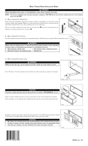
10. Remove the transition section of the conveyor frame.
Place the transition floor panel into place atop the support
brackets. See Figure 2-23.
11. Replace the transition (center) conveyor section, as shown
in Figure 2-24.
Figure 2-23
Installing the Transition
Floor Panel
Figure 2-24
Replacing the
Transition Frame

2-19
SECTION 2
INSTALLATION
INSTALLING THE CONVEYOR FRAME AND BELT
1. Insert the conveyor frame into the oven as follows:
For TRI TANDEM ovens, slide
one center section and one end
section of the frame into EACH
END of the oven. The four sections
should butt against each other.
For QUAD TANDEM ovens, slide
two intermediate sections and one
end section of the frame into EACH
END of the oven. Butt the two
inner intermediate
sections against the
transition (center) frame
section. The other
frame sections should
butt against each other.
FOR
ALL TYPES OF OVENS, ENSURE THAT THE DRIVE
SECTION/END OF THE CONVEYOR FRAME IS PLACED ON
THE SAME END OF THE OVEN AS THE CONVEYOR DRIVE
MOTOR.
Figure 2-25a
Installing the Conveyor Frame-
Tandem and Double Tandem Ovens
Figure 2-25b
Installing the Conveyor Frame-
Tri Tandem Ovens
Figure 2-25c
Installing the Conveyor Frame-
Quad Tandem Ovens
For a TANDEM or DOUBLE
TANDEM oven, slide the conveyor
frame assembly into either end of
the oven.

2-20
SECTION 2
INSTALLATION
2. Slide the conveyor belt
through the support rods
underneath the frame, and
thread it through the oven.
Then, reach through the oven
window and pull the free end
of the belt through the oven
so that it lies atop the
conveyor frame.
Check that the links on the
conveyor are oriented as
shown in Figure 2-26.
Direction
of travel
Figure 2-26
Conveyor Link Orientation
3. Connect the inside master
links. Check that the links
are oriented as shown in
Figure 2-27.
4. Connect the outside master
links. Note that the outside
master links have right and
left sides. The right-side
master link has an open hook
facing you, as shown in
Figure 2-28.
Figure 2-27
Inside Master Links
Correct
position
Incorrect
position
Direction
of travel
Figure 2-28
Outside Master Links
/