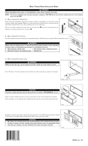
Page is loading ...

2-1
SECTION 2
INSTALLATION
SECTION 2
INSTALLATION
WARNING
Do not obstruct the flow of combustion and ventilation air to and from your oven. There must be no
obstructions around or underneath the oven.
CAUTION
For additional installation information, refer to the PS360 Pre-Installation Procedures Manual (Middleby
Marshall P/N 88210-0024) or contact your local Authorized Service Agent.
NOTE
There must be adequate clearance between the oven and combustible construction. Clearance must
also be provided for servicing and for operation.
NOTE
Wiring diagrams are contained in this manual (Section 5, Electrical Schematics) and are also
located inside the Machinery Compartment Access Panel.
NOTE
All aspects of the oven installation, including placement, utility connections, and ventilation requirements, must
conform with any applicable local and national codes. These codes supercede the requirements and guidelines
provided in this manual.
NOTE
In U.S.A., the oven installation must conform with local codes, or in the absence of local codes, with the National
Fuel Gas Code, ANSI Z223.1. The oven, when installed, must be electrically grounded in accordance with local
codes, or in the absence of local codes, with the National Electrical Code (NEC), or ANSI/NFPA70.
NOTE
In Canada, the oven installation must conform with local codes, or in the absence of local codes, with the Natural
Gas Installation Code, CAN/CGA-B149.1, or the Propane Gas Installation Code, CAN/CGA-B149.2, as applicable.
The oven, when installed, must be electrically grounded in accordance with local codes, or in the absence of local
codes, with the Canadian Electrical Code CSA, C22.2, as applicable.
NOTE
For Australian installation, the oven installation must conform with AGA Code, AG601, and with any requirements of
the appropriate statutory authority.

2-2
SECTION 2
INSTALLATION
Item Part # Description Tandem Double Tandem Tri Tandem Quad Tandem
1 22361-0001 Flexible Gas Hose 2434
2 22450-0028 Adjustable Legs 8 8 12 16
3 30773 Flue Vent, 14"Lg. 2 - - -
4 30759 Flue Vent, 29-1/2"Lg. - 2 3 4
5 30758 Flue Vent, 50" Lg. - 2 - -
6 21256-0008 Screw, 10-32 x 3/8 A/R A/R A/R A/R
7 35000-1103 Conveyor End Stop - PS360 1 2 - -
35000-1899 Conveyor End Stop - PS360WB
8 21292-0001 Scr, #2PT 10-16 x 3/4 Hx Wsh A/R A/R A/R A/R
9 33984 Thermocouple 2434
10 27276-0001 Cable Clamp 2434
11 1002040 Warranty, Parts & Serv. Dist.List 1111
12 39223 Owners Operating and Installation Manual (English) 1111
13 27126-0238 11 Piece Hex Key Set 1111
14 31389 Silicone Tubing, 36 (914mm) L x 2434
5/16 (8mm) ID x 7/16 (11mm) OD
- 35000-1454
Machinery Compartment Trim Strip
1222
- 35000-1456 Front Gasket Spacer 2444
- 35000-1457 Rear Gasket Spacer 2444
- 37200-0013
Baking Chamber Gasket and Frame - PS360
1222
32483
Baking Chamber Gasket and Frame - PS360WB
Fig. 2-1 - Installation Kit
I. INSTALLATION KIT
II. TRANSITION CHAMBER COMPONENTS (Quad Tandem Ovens Only)
Qty. Part # Description
1 37000-0696 Floor Panel - PS360
32457 Floor Panel - PS360WB
1 48009-0024 Top Panel - PS360
32456 Top Panel - PS360WB
Qty. Part # Description
1 48009-0025 Side Wall
1 35000-1748 Rear Support
2 35000-1749 Front Support
2 37000-0697 Top Support Channel - PS360
32455 Top Support Channel - PS360WB

2-3
SECTION 2
INSTALLATION
The rate of air flow exhausted through the ventilation
system may vary depending on the oven configuration and
hood design. Consult the hood manufacturer or ventilation
engineer for these specifications.
To avoid a negative pressure condition in the kitchen area,
return air must be brought back to replenish the air that was
exhausted. A negative pressure in the kitchen can cause
heat- related problems to the oven components as if there
were no ventilation at all. The best method of supplying
return air is through the heating, ventilation and air
conditioning (HVAC) system. Through the HVAC system,
the air can be temperature-controlled for summer and
winter. Return air can also be brought in directly from
outside the building, but detrimental effects can result from
extreme seasonal hot and cold temperatures from the
outdoors.
NOTE: Return air from the mechanically driven system
must not blow at the opening of the baking chamber. Poor
oven baking performance will result.
Fig. 2-2 - Ventilation System
A. REQUIREMENTS
A mechanically driven ventilation system is required for the
oven.
PROPER VENTILATION OF THE OVEN IS THE
RESPONSIBILITY OF THE OWNER.
B. RECOMMENDATIONS
NOTE THAT THE HOOD DIMENSIONS SHOWN IN FIG-
URE 2-2 ARE RECOMMENDATIONS ONLY. LOCAL
AND NATIONAL CODES WILL VARY, AND MUST BE
FOLLOWED WHEN INSTALLING THE VENTILATION
SYSTEM. ANY APPLICABLE LOCAL AND NATIONAL
CODES SUPERSEDE THE RECOMMENDATIONS
SHOWN IN THIS MANUAL.
III. VENTILATION SYSTEM
IMPORTANT
Where national or local codes require
the installation of fire suppression
equipment or other supplementary
equipment, DO NOT mount the equip-
ment directly to the oven.
MOUNTING SUCH EQUIPMENT ON
THE OVEN MAY:
VOID AGENCY CERTIFICATIONS
RESTRICT SERVICE ACCESS
LEAD TO INCREASED SERVICE
EXPENSES FOR THE OWNER
C. OTHER VENTILATION CONCERNS
Special locations, conditions, or problems may re-
quire the services of a ventilation engineer or special-
ist.
Inadequate ventilation can inhibit oven performance.
It is recommended that the ventilation system and
duct work be checked at prevailing intervals as speci-
fied by the hood manufacturer and/or HVAC engineer
or specialist.

IV.
THERMOCOUPLE
INSTALLATION
1. Install the thermocouple sensing bulb into the correct
hole in the rear of the oven, as shown in Figure 2-3.
2. Thread the thermocouple lead through the grommet
and into the machinery compartment.
3. Remove the right-side access panel of the machinery
compartment.
4. Thread the thermocouple lead through the side of the
machinery compartment as shown in Figure 2-4, and
into the electrical box (at the right-front of the machin-
ery compartment).
5. Connect the thermocouple leads to the temperature
controller as shown in Figure 2-5.
6. Repeat Steps 1-5 for each of the other oven sections in
the installation.
8=White=Positive
7=Red=Negative
R=No Connection
Ground=Shielded cable
Figure 2-3
Thermocouple Installation Locations
Figure 2-4
Placing the Thermocouple Leads
Figure 2-5
Thermocouple Lead
Connections
Use for conveyor
Use for conveyor
Thread lead into
machinery
compartment here
Thread lead into
machinery
compartment here

Figure 2-6
Exploded View -
Oven Stand
B. JOINING THE OVEN BODIES
For TANDEM and DOUBLE TANDEM installations, perform
Steps 1-8 in this section to join the ovens.
For TRI TANDEM installations, perform Steps 1-8 to join
two of the ovens together, and ensure that they are level;
then, repeat Steps 1-8 to join the third oven to the two that
have already been assembled.
For QUAD TANDEM installations, perform Steps 1-8 for
EACH PAIR of ovens, producing two sets of two joined
ovens. Do not assemble the center bridge section at this
time.
Figure 2-7
Oven Positioning and Alignment
Alignment
plate
Slot for
alignment
plate
Sealing gasket
assembly (pre-
mounted)
LEFT OVEN RIGHT OVEN
1. Determine the proper position of the ovens by referring
to Figure 2-7. Then, move the ovens to their approximate
final locations.
2. Check that the top and bottom air finger retaining
screws are present on all mating ends of the oven
sections. See Figure 2-7. The screws prevent the air
fingers from sliding in between the oven sections.
V. ASSEMBLY
A. OVEN STAND
If the installation includes upper ovens
mounted atop lower ovens, the ovens
must be stacked before joining the
tandem ovens together.
If the installation includes ovens that
are to be mounted on stands, assemble
the ovens to the stands before joining
the ovens together. An exploded view
of the stand is shown in Figure 2-6.
NOTE: The Sealing Gasket Assembly may be
pre-mounted to EITHER of the two ovens.
Air finger
retaining
screws
Attachment
plates inc. w/
upper oven

2-6
SECTION 2
INSTALLATION
Figure 2-9 - Bolts and Spacers
Figure 2-10 - Aligning the Sections
Figure 2-8 - Cooling Fan Removal
3. Remove the rear axial cooling fans that are adjacent to
the mating sides of the ovens. The fans may either be
completely disconnected, or left attached by their
wiring as shown in Figure 2-8.
Mating surface of
ovens (shown from
lower rear)
Wiring is still
connected
2-1/2 x 8
(64 x 203mm)
spacers
2-1/2 x 2-1/2
(64 x 64mm)
spacers
Bolts
4. Insert three of the supplied 1/2 x 5 bolts through the
holes in the frame of the right oven, pointing outward as
shown in Figure 2-9. Then, slide the spacers into place
on the bolts.
5. Push the ovens together. Check that the mounting
bolts, alignment plate, and sealing gasket are all
properly aligned. See Figure 2-10.
6. Tighten all of the attaching bolts. Check that the
mating edges of the ovens align properly. If gaps
appear between the tops of the ovens, it will be
necessary to loosen the connecting bolts and realign
the ovens.

2-7
SECTION 2
INSTALLATION
7. Attach the front trim strip between the two ovens, as
shown in Figure 2-11.
8. Replace the rear axial cooling fans. See Figure 2-8.
9. Perform one of the following, as appropriate:
For PS360/360WB Tandem and Double Tandem
installations, skip ahead to Part D, INSTALLING
THE CONVEYOR FRAME AND BELT (Page 2-9).
For PS360/360WB Tri Tandem installations, perform
Steps 1-8 again to attach the third oven to the two
that have just been assembled. Then, skip ahead to
Part D, INSTALLING THE CONVEYOR FRAME
AND BELT (Page 2-9).
For PS360/360WB Quad Tandem installations,
perform Steps 1-8 again to attach the two remaining
ovens to each other. Then, continue on to Part C,
INSTALLING THE CENTER TRANSITION.
Figure 2-11 - Trim Strip Installation
Figure 2-12
Support Channel Installation - Lower Oven
Figure 2-13
Support Channel Installation - Upper Oven
Support
channels
C. INSTALLING THE CENTER TRANSITION
1. Install the upper support channels to the two center
ovens as shown in Figures 2-12 and 2-13.
Trim strip
Support
channels

2-8
SECTION 2
INSTALLATION
Figure 2-16
Floor Panel
Installation
Figure 2-17
Installing
the Frame
Figure 2-14
Support Brackets,
Lower Oven
2. Align the two center ovens so that they are level and
20 (508mm) apart. Then, attach the two angled
support brackets between the two center ovens, as
shown in Figures 2-14 and 2-15.
Note that a LOWER OVEN uses different support
brackets for the front and rear, while an UPPER OVEN
uses identical brackets on the front and rear.
4. Place the transition floor panel into place atop the
support brackets. See Figure 2-16.
20
508mm
Upper surfaces of
brackets must be level
with each other
20
508mm
Figure 2-15
Support Brackets,
Upper Oven
5. Install the transition (center) conveyor section, as
shown in Figure 2-17. Align the conveyor section so
that it extends the same distance into the two oven
chambers.

2-9
SECTION 2
INSTALLATION
D. INSTALLING THE CONVEYOR FRAME AND BELT
FOR ALL TYPES OF OVENS, ENSURE THAT THE
DRIVE SECTION/END OF THE CONVEYOR FRAME IS
PLACED ON THE SAME END OF THE OVEN AS THE
CONVEYOR DRIVE MOTOR.
1. Insert the conveyor frame into the oven as follows:
For a TANDEM or DOUBLE TANDEM oven,
slide one hinged conveyor frame section
into each end of the oven. The two
sections butt against each other at the
gap between the two oven sections. See
Figure 2-18.
For TRI TANDEM ovens, slide one intermediate
frame section into the oven (from either end).
Center this section inside the oven.
Then, slide one intermediate
section and one end section of
the frame into EACH END of the
oven. All five sections should
butt against each other. See
Figure 2-19.
For QUAD TANDEM ovens, slide two intermediate
sections and one end section of the frame into EACH
END of the oven. Butt the two inner intermediate
sections against the transition (center) frame
section. The other frame sections
should butt against each other.
See Figure 2-20.
Figure 2-18
Tandem and Double Tandem
Conveyor Installation
Figure 2-19
Tri Tandem Conveyor
Installation
Figure 2-20
Quad Tandem Conveyor Installation
Intermediate
sections
Center section
(transition)
Intermediate
sections
End
section
End
section
End
section
End
section
Hinged
end section
Hinged
end section
Intermediate
sections

2-10
SECTION 2
INSTALLATION
Figure 2-23
Outside Master
Links
Direction
of travel
4. Connect the outside master links. Note that the
outside master links have right and left sides. The
right-side master link has an open hook facing you, as
shown in Figure 2-23.
2. Slide the conveyor belt through the support rods
underneath the frame, and thread it through the oven.
Then, reach through the oven window and pull the free
end of the belt through the oven so that it lies atop the
conveyor frame.
After the belt has been pulled through the oven, check
the following:
The conveyor belt links must be oriented as shown
in Figure 2-21.
The smooth side of the conveyor belt must face
UP.
3. Connect the inside master links. Check that the links
are oriented as shown in Figure 2-22.
Figure 2-21 - Conveyor Link Orientation
Figure 2-22 - Inside Master Links
Direction
of travel
Correct
position
Incorrect
position

2-11
SECTION 2
INSTALLATION
Latches
Latches
Figure 2-24 - Transition Section Final Assembly
Figure 2-25
Conveyor Motor and Drive Chain Assembly
5. For a TANDEM, DOUBLE TANDEM, or TRI TANDEM
oven installation, skip ahead to Step 9. For a QUAD
TANDEM oven installation, continue on to Step 6.
6. Slide the top transition panel into place. Then, slide
the two transition side panels into place. See Figure
2-24.
7. If the four latches are not already attached to the side
and top transition panels, attach them in place as
shown in Figure 2-24.
8. Fasten the latches on the side and top panels to hold
the panels in place.
9. LOOSELY attach the conveyor drive motor to the end
wall of the oven, as shown in Figure 2-25.
10. Assemble the conveyor drive chain in place on the
motor and conveyor drive sprockets.
11. Position the motor to adjust the tension of the drive
chain. The deflection of the chain should be 3/4
(19mm). DO NOT OVERTIGHTEN THE DRIVE CHAIN.
Then, tighten the motor in place.
12. Assemble the end plugs and motor housing onto the
oven.
13. TANDEM AND DOUBLE TANDEM OVENS ONLY:
Assemble the end stops, conveyor crumb trays, and
conveyor extension covers onto the oven. These
components are illustrated in Figure 1-1 (Page 1-2).

2-12
SECTION 2
INSTALLATION
VI. ELECTRICAL SUPPLY
WARNING
Authorized supplier personnel normally accomplish the
connections for the ventilation system, electric supply,
and gas supply, as arranged by the customer. Following
these connections, the factory-authorized installer can
perform the initial startup of the oven.
NOTE: The electric supply installation must satisfy the
requirements of the appropriate statutory authority, such
as the National Electrical Code (NEC), ANSI/NFPA70,
(U.S.A.); the Canadian Electrical Code, CSA C22.2; the
Australian Code AG601; or other applicable regulations.
NOTE: The electric supply connection must meet all
national and local electrical code requirements.
Check the oven data plate before making any electric
supply connections. Electric supply connections must
agree with data on the oven data plate. See Figure 2-26.
A fused disconnect switch or a main circuit breaker
(customer furnished) MUST be installed in the electric
supply line for each oven. It is recommended that this
switch/circuit breaker have lockout/tagout capability.
The supply conductors must be of the size (#14 AWG,
copper) recommended. Refer to the wiring diagrams in
Section 5 of this manual.
All gas oven electric supply connections are made via the
electrical junction box on the rear of the oven, shown in
Figure 2-27. The power lines then connect to the oven
circuits through the Machinery Compartment Access
Panel Safety Switch. This switch interrupts electric power
to the oven when the Machinery Compartment Access
Panel is opened.
CAUTION
Before connecting incoming power to the oven, measure
the voltage of each input leg to neutral. The expected
voltage is approximately 120V. ANY voltage reading
exceeding 130V indicates that the supply has a high leg.
CONNECTING A HIGH LEG TO THE OVEN VOIDS ALL
OVEN WARRANTIES. Connecting a high leg to the
black lead of the oven can severely damage the ovens
electrical and electronic components.
CAUTION
DO NOT CONNECT BLACK WIRE TO
HIGH LEG. VOLTAGE OF THE BLACK
AND WHITE WIRES MUST BE NO
HIGHER THAN 130 VAC
Figure 2-26
Oven Data Plate
FOR DOMESTIC OVENS (WITHOUT EXTERNAL
TRANSFORMERS):
In the junction box on the rear of the oven, connect one
208 - 240V supply line to the black wire and the other
208 - 240V supply line to the red wire. Connect the
electric supply ground wire to the oven ground screw
located in the junction box. If necessary, have the
electrician supply the ground wire. Do NOT use the
wiring conduit or other piping for ground connections!
FOR EXPORT OVENS (WITH EXTERNAL
TRANSFORMERS):
First, position the transformer on the LEFT REAR wall
of the oven (as space permits), and fasten it in place
using the supplied mounting hardware.
Then, refer to the appropriate wiring diagram in Section
5 of this manual to determine the correct transformer
connections for the supply lines. Connect the electric
supply ground wire to the oven ground screw located
in the junction box. If necessary, have the electrician
supply the ground wire. Do NOT use the wiring conduit
or other piping for ground connections!

2-13
SECTION 2
INSTALLATION
Figure 2-27
Utility Connection Locations
VII.GAS SUPPLY
A. CONNECTION
Check the ovens gas supply requirements before making
the gas utility connection. Gas supply requirements are
listed on the ovens data plate (Figure 2-26) and in the Oven
Specifications table (Page 1-1 of this manual).
Check the oven data plate (see Figure 2-26) to determine
the type of gas (Propane or Natural) to be used with the
oven.
Refer to the instructions in the gas hose package (included
in the Base Pad Kit) before connecting the gas line. One
gas line connection method is shown in Figure 2-28;
however, compliance with the applicable standards and
regulations is mandatory.
Inlet, regulated, and pilot gas pressure readings can be
taken using a U tube manometer at the tap locations
shown in Figure 2-29.
One 90° elbow equals a 4 (1.22m) length of pipe. The
recommended pipe sizes are larger than usually required
to eliminate any operation problems. It is much less
expensive to make the initial installment large enough to do
the job rather than redoing the job later.
NOTE
The installation must conform with local codes or in the
absence of local codes, with the National Fuel Gas
Code, ANSI Z223.1-latest edition.
In Australia, the installation must conform with AGA
Code AG601 and with any requirements of the
appropriate statutory authority.
CANADIAN:
CAN/CGA-B 149.1 Natural Gas Installation Code
CAN/CGA-B 149.2 Propane Installation Code
CAUTION
DURING PRESSURE TESTING NOTE ONE OF
THE FOLLOWING:
1. The oven and its individual shutoff valve must
be disconnected from the gas supply piping
system during any pressure testing of that system
at test pressure in excess of 1/2 psi (3.45 kPa).
2. The oven must be isolated from the gas supply
piping system by closing its individual manual
shutoff valve during any pressure testing of the
gas supply piping system at test pressure equal to
or less than 1/2 psi (3.45 kPa).
3. If incoming pressure is over14 W.C. (35mbar),
a separate regulator MUST be installed in the line
BEFORE the individual shutoff valve for the oven.
WARNING: To prevent damage to the
control valve regulator during initial turn-
on of gas, it is very important to open the
manual shutoff valve very slowly.
After the initial gas turn-on, the manual shutoff
valve must remain open except during pressure
testing as outlined in the above steps or when
necessary during service maintenance.
Lower Oven Upper Oven
Electrical
Junction Box
Gas Utility
Connection
Gas Utility
Connection
Electrical
Junction Box

2-14
SECTION 2
INSTALLATION
Certain safety code requirements exist for the installation
of gas ovens; refer to the beginning of Section 2 for a list of
the installation standards. In addition, because the oven is
equipped with casters, the gas line connection shall be
made with a connector that complies with the Standard for
Connectors for Movable Gas Appliances, ANSI Z21.69 (in
U.S.A.), or, if applicable, Connectors for Movable Gas
Appliances, CAN/CGA-6.16 (in Canada), as well as a
quick-disconnect device that complies with the Standard
for Quick-Disconnect Devices for Use With Gas Fuel,
ANSI Z21.41 (in U.S.A.), or, if applicable, Quick-Discon-
nect Devices for Use With Gas Fuel, CAN1-6.9 (in Canada).
B. GAS CONVERSION
It is possible to convert ovens from natural to propane gas,
or from propane to natural gas, by changing the main and
pilot orifices.
WARNING: All installations, conversions and service work
must be performed by an authorized service agent.
NOTE: In Canada, to conform with the CAN/CGA-B149.2
propane installation code, the oven must be ordered
propane. It may not be converted in the field.
Figure 2-28
Flexible Gas Hose Installation
Appliance
Connection/Male
Nipple
Flexible
Gas Hose
Full-Flow Gas
Shutoff Valve
To Gas
Supply Pipe
90°
Elbow
Manual
shutoff valve
Pilot pressure tap
(where pilot gas
pressure is measured)
Combination Gas
Control Valve (Safety
Regulator)
Inlet pressure
tap (where
incoming gas
pressure is
measured)
Manifold
pressure
tap (where
manifold gas
pressure is
measured)
On/Off Knob - Always
leave in ON position
Low Flame
Bypass Line
High Flame
Solenoid Valve
Burner Blower
Gas Burner
Figure 2-29
Gas Burner and Piping Assembly
/