
NOTE: Read the entire instruction manual before starting the
installation.
This symbol → indicates a change since the last issue.
TABLE OF CONTENTS
SAFETY CONSIDERATIONS.....................................................1
INTRODUCTION..........................................................................2
INSTALLATION GUIDELINE....................................................2
Residential New Construction..................................................2
Add-On Replacement (Retrofit)...............................................2
Seacoast (For Air Conditioners Only) .....................................2
ACCESSORY DESCRIPTIONS...................................................2
Compressor Crankcase Heater..................................................2
Evaporator Freeze Thermostat..................................................2
Winter Start Control .................................................................2
Compressor Start Assist—PTC................................................2
Compressor Start Assist Capacitor/Relay................................2
Low-Ambient Controller ..........................................................2
MotorMaster™ Control ............................................................2
Low-Ambient Pressure Switch.................................................2
Wind Baffle...............................................................................3
Coastal Filter.............................................................................3
Support Feet..............................................................................3
Liquid-Line Solenoid Valve.....................................................3
Thermostatic-Expansion Valve.................................................3
Isolation Relay..........................................................................3
LOW-AMBIENT GUIDELINE.....................................................3
LONG-LINE GUIDELINE............................................................3
Approved Systems....................................................................3
Interconnecting Tubing Sizing .................................................3
Metering Device Sizing............................................................6
Liquid-Line Solenoid And Tubing Configuration...................7
Charging Information................................................................8
2–Speed Applications ...............................................................8
UNIT IDENTIFICATION .............................................................8
Product Number Stamped on Unit-Rating Plate......................8
Serial Number Identification....................................................9
CABINET.....................................................................................10
Remove Top Cover—Before 1/1/92......................................10
Remove Fan-Motor Assembly—Before 1/1/92.....................10
Information Plate—Reliant Products......................................10
Control-Box Cover—Cube Products......................................10
Remove Top Cover— After 1/1/92 .......................................10
Remove Fan-Motor Assembly—After 1/1/92........................11
ELECTRICAL..............................................................................12
Aluminum Wire......................................................................12
Contactors................................................................................13
Capacitors................................................................................14
Cycle Protector........................................................................15
Crankcase Heater....................................................................16
Time-Delay Relay...................................................................16
Pressure Switches....................................................................17
Defrost Thermostats................................................................18
Defrost-Control Board............................................................18
Fan Motors..............................................................................21
Service Alarm Control Board.................................................21
Outdoor Thermostat(s)............................................................22
Compressor Plug.....................................................................24
Low-Voltage Terminals..........................................................25
RECIPROCATING COMPRESSOR ..........................................25
Mechanical Failures................................................................25
Electrical Failures ...................................................................26
System Cleanup After Burnout..............................................27
Compressor Removal And Replacement ...............................27
COPELAND SCROLL COMPRESSOR ....................................28
Features ...................................................................................28
Troubleshooting ......................................................................28
Discharge Thermostat.............................................................28
Discharge Solenoid Valve......................................................28
MILLENNIUM SCROLL COMPRESSOR................................29
Features ...................................................................................29
Compressor Protection............................................................29
Troubleshooting ......................................................................29
Scroll Compressor, 3–Phase Monitor.....................................29
TWO-SPEED SYSTEM ..............................................................29
Cautions and Warnings...........................................................29
System Functions....................................................................29
Factory Defaults......................................................................33
Major Components..................................................................33
LED Function/Malfunction Lights.........................................34
Troubleshooting ......................................................................34
REFRIGERATION SYSTEM .....................................................35
Refrigeration Cycle.................................................................35
Leak Detection........................................................................35
Brazing....................................................................................37
Service Valves ........................................................................38
Check-Flo-Rater™ (Bypass-Type) Heat Pumps Only...........39
Reversing Valve......................................................................39
Thermostatic-Expansion Valves (TXV).................................40
Thermostatic-Expansion Valve (Bi-Flow TXV)....................41
Coil Removal..........................................................................41
Liquid-Line Strainer (Heat Pumps Only) ..............................41
Accumulator............................................................................43
Contaminant Removal ............................................................43
System Charging.....................................................................43
Checking Charge.....................................................................43
CARE AND MAINTENANCE...................................................45
SAFETY CONSIDERATIONS
Service and repair of these units should be attempted only by
trained service technicians familiar with Bryant standard service
instructions and training manual.
All equipment should be installed in accordance with accepted
practices and unit Installation Instructions, and in compliance with
all national and local codes.
Power should be turned off when servicing or repairing electrical
components. Extreme caution should be observed when trouble-
shooting electrical components with power on. Observe all warn-
ing notices posted on equipment.
Application Guide and
Service Manual
AIR CONDITIONERS AND HEAT PUMPS
USING R-22 REFRIGERANT
Cancels: AP01-3, SM01,02-4 SM01,02-5
10-00
—1—

Refrigeration system contains refrigerant under pressure. Extreme
caution should be observed when handling refrigerants. Wear
safety glasses and gloves to prevent personal injury. During
normal system operation, some components are hot and can cause
burns. Rotating fan blades can cause personal injury. Appropriate
safety considerations are posted throughout this manual where
potentially dangerous techniques are addressed.
It is important to recognize safety information. This is the
safety-alert symbol
. When you see this symbol on the unit and
in instructions or manuals, be alert to the potential for personal
injury.
Understand the signal words DANGER, WARNING, and CAU-
TION. These words are used with the safety-alert symbol. DAN-
GER identifies the most serious hazards which will result in severe
personal injury or death. WARNING signifies hazards which
could result in personal injury or death. CAUTION is used to
identify unsafe practices which would result in minor personal
injury or product and property damage. NOTE is used to highlight
suggestions which will result in enhanced installation, reliability,
or operation.
WARNING: Improper installation, adjustment, alter-
ation, service, maintenance, or use can cause explosion,
fire, electrical shock, or other conditions which may
cause personal injury, death, or property damage. Consult
a qualified installer, service agency, or your distributor or
branch for information or assistance. The qualified in-
staller or agency must use factory-authorized kits or
accessories when modifying this product.
INTRODUCTION
This service manual enables a service technician to service, repair,
and maintain a family of similar air conditioners and heat pumps.
It covers standard single-speed products and 2–speed products
only. For variable-speed products, refer to the respective service
manuals.
INSTALLATION GUIDELINE
I. RESIDENTIAL NEW CONSTRUCTION
Specifications for this unit in the residential, new-construction
market require the outdoor unit, indoor unit, refrigerant-tubing
sets, metering device, and filter drier listed in Product Data Sheet
(PDS). DO NOT DEVIATE FROM PDS. Consult unit Installation
Instructions for detailed information.
II. ADD-ON REPLACEMENT (RETROFIT)
Specifications for this unit in the add-on replacement/retrofit
market require change-out of outdoor unit, metering device, and all
capillary-tube coils. Change-out of indoor coil is recommended.
There can be no deviation.
1. If system is being replaced due to compressor electrical
failure, assume acid is in system. If system is being replaced
for any other reason, use approved acid test kit to determine
acid level. If even low levels of acid are detected, install
factory-approved, suction-line filter drier in addition to the
factory-supplied, liquid-line filter drier. Remove the
suction-line filter drier as soon as possible, with a maximum
of 72 hr.
2. Drain oil from low points or traps in suction-line and
evaporator if they were not replaced.
3. Change out indoor coil or verify existing coil is listed in the
Product Data Sheets.
4. Replace outdoor unit.
5. Install liquid-line filter drier.
6. If suction-line filter drier was installed for system clean up,
operate system for 10 hr. Monitor pressure drop across
drier. If pressure drop exceeds 3 psig, replace suction-line
and liquid-line filter driers. Be sure to purge system with
dry nitrogen and evacuate when replacing filter driers.
Continue to monitor pressure drop across suction-line filter
drier. After 10 hr of run time, remove suction-line filter
drier and replace liquid-line filter drier. Never leave
suction-line filter drier in system longer than 72 hr
(actual time).
7. Charge system. (See unit information plate.)
III. SEACOAST (FOR AIR CONDITIONERS ONLY)
Installation of these units in seacoast locations requires the use of
a coastal filter. (See section on cleaning.)
ACCESSORY DESCRIPTIONS
Refer to Table 1 for an Accessory Usage Guide for Air Condi-
tioners and Heat Pumps. See Model-specific product literature for
any kit part number. Refer to the appropriate section below for a
description of each accessory and its use.
I. COMPRESSOR CRANKCASE HEATER
An electric heater which mounts to base of compressor to keep
lubricant warm during off cycles. Improves compressor lubrication
on restart and minimizes chance of refrigerant slugging and oil
pumpout. The crankcase heater may or may not include a
thermostat control. For units equipped with crankcase heaters,
apply power for 24 hr before starting compressor.
II. EVAPORATOR FREEZE THERMOSTAT
An SPST temperature-activated switch stops unit operation when
evaporator reaches freeze-up conditions.
III. WINTER START CONTROL
An SPST delay relay which bypasses the low-pressure switch for
approximately 3 minutes to permit startup for cooling operation
under low-load conditions.
IV. COMPRESSOR START ASSIST—PTC
Solid-state electrical device which gives a ″soft″ boost to the
compressor at each start.
V. COMPRESSOR START ASSIST CAPACITOR/RELAY
Start capacitor and start relay gives ″hard″ boost to compressor
motor at each start. Required with Liquid-Line Solenoid or
hard-shutoff TXV for all equipment.
VI. LOW-AMBIENT CONTROLLER
Low-ambient controller is a cycle-control device activated by a
temperature sensor mounted on a header tube of the outdoor coil.
It is designed to cycle the outdoor fan motor in order to maintain
condensing temperature within normal operating limits (approxi-
mately 100°F high, and 60°F low). The control will maintain
working head pressure at low-ambient temperatures down to 0°F
when properly installed.
VII. MOTORMASTER™ CONTROL
A fan speed-control device activated by a temperature sensor. It is
designed to control condenser fan-motor speed in response to the
saturated, condensing temperature during operation in cooling
mode only. For outdoor temperature down to -20°F, it maintains
condensing temperature at 100°F±10°F. Requires a ball-bearing
fan motor.
VIII. LOW-AMBIENT PRESSURE SWITCH
A long-life pressure switch which is mounted to outdoor unit
service valve. It is designed to cycle the outdoor fan motor in
response to condenser pressure in cooling mode in order to
maintain head pressure within normal operating limits (approxi-
mately 100 psig to 225 psig). The control will maintain working
head pressure at low-ambient temperatures down to 0°F when
properly installed.
—2—

IX. WIND BAFFLE
A field-fabricated sheet-metal cover used to stop prevailing winds
or where outdoor ambient temperature is less than 55°F during unit
operation of cooling mode.
X. COASTAL FILTER
A mesh screen inserted under top cover and inside base pan to
protect condenser coil from salt damage without restricting air-
flow.
XI. SUPPORT FEET
Four adhesive plastic feet which raise unit 4 in. above mounting
pad. This allows sand, dirt, and other debris to be flushed from unit
base; minimizes corrosion.
XII. LIQUID-LINE SOLENOID VALVE
An electrically operated shutoff valve to be installed at outdoor or
indoor unit (depending on tubing configuration) which stops and
starts refrigerant liquid flow in response to compressor operation.
Maintains a column of refrigerant liquid ready for action at next
compressor-operation cycle and prevents liquid migration during
the off cycle.
XIII. THERMOSTATIC-EXPANSION VALVE
A modulating flow-control device which meters refrigerant flow
rate into the evaporator in response to the superheat of the
refrigerant gas leaving the evaporator. Only use factory-specified
TXV’s.
XIV. ISOLATION RELAY
A DPDT relay which switches the low-ambient controller out of
the outdoor fan-motor circuit when the heat pump switches to
heating mode.
LOW-AMBIENT GUIDELINE
The minimum operating temperature for these units in cooling
mode is 55°F outdoor ambient without additional accessories. This
equipment may be operated in cooling mode at ambient tempera-
tures below 55°F when the accessories listed in Table 1 are
installed. Wind baffles are required when operating in cooling
mode at ambients below 55°F. Refer to Fig. 1 or 2 and Table 2 or
3 for wind baffle construction details.
LONG-LINE GUIDELINE
This Long-Line Application Guideline applies to all Bryant
residential air conditioner and heat pump split systems that have a
nominal capacity of 18,000 to 60,000 Btuh. This guideline
provides required system changes and accessories necessary for
any residential product having piping requirements greater than 50
ft or installations where indoor unit is located above outdoor unit.
This guideline is intended to cover applications outside the
standard Installation Instructions. This guideline is for standard,
single-speed products. For applications involving 2-speed prod-
ucts, refer to Section VI first.
NOTE: The presale literature for outdoor unit must be referred to
in conjunction with this guideline.
I. APPROVED SYSTEMS
Any residential indoor/outdoor unit combination listed in the
outdoor unit presale literature is an approved system, EXCEPT the
following:
• Indoor coils with capillary-metering devices
• All equipment less than nominal 18,000 Btuh
• All 1/4-in. and 5/16–in. liquid-line applications
• Any indoor furnace coil/fan coil not listed in outdoor unit
presale literature
• Any application which has interconnecting tubing with an
equivalent length greater than 175 ft
II. INTERCONNECTING TUBING SIZING
Table 4 lists recommended interconnecting vapor-line diameters
for equivalent total-line lengths. All residential split systems
installed in long-line applications must use only 3/8-in. liquid
lines. Equivalent line length equals the linear length (measured) of
interconnecting vapor tubing plus losses due to elbows. (See Table
5 and Fig. 3.) Liquid lines larger than 3/8-in. OD greatly increase
charge quantity of the system. Excessive charge increases risk of
migration and compressor damage. Table 4 provides the estimated
percentage of nominal cooling-capacity losses based on the stan-
dard, required vapor line size versus what is selected for the
long-line application. Since the vapor line is the discharge line in
heating mode, losses are minimal.
TABLE 1—REQUIRED FIELD-INSTALLED ACCESSORIES FOR AIR CONDITIONERS AND HEAT PUMPS
ACCESSORY
REQUIRED FOR
LOW-AMBIENT
APPLICATIONS
(BELOW 55°F)
REQUIRED FOR
LONG-LINE
APPLICATIONS*
(OVER 50 FT)
REQUIRED FOR
SEA COAST
APPLICATIONS
(WITHIN 2 MILES)
Crankcase Heater Yes Yes No
Evaporator Freeze Thermostat Yes No No
Winter Start Control Yes† No No
Accumulator No No No
Compressor Start Assist
Capacitor and Relay
Yes Yes No
Low Ambient Controller,
MotorMaster™ Control,
or
Low-Ambient Pressure Switch
Yes No No
Wind Baffle See Low-Ambient Instructions No No
Coastal Filter No No Yes
Support Feet Recommended No Recommended
Liquid-Line Solenoid Valve
or
Hard-Shutoff TXV
No
See Long-Line
Application
Guideline
No
Ball-Bearing Fan Motor Yes‡ No No
Isolation Relay Yes** No No
*For tubing line sets between 50 and 175 ft, refer to Residential Split-System Long-Line Application Guideline.
†Only when low-pressure switch is used.
‡Required for Low-Ambient Controller (full modulation feature) and MotorMaster™ control only.
** Required on Heat Pumps only.
—3—

Fig. 1—Wind Baffle Construction for Reliant Units
A95445
1
/
4
″ x
3
/
8
″ (5.56 x 9.53) SLOT
4 REQ'D
1
/
2
″
(12.7)
J
7
/
16
″
(11.6)
C
A
7
/
16
″
(11.6)
B
5
5
/
16
″
(151.5)
1
/
2
″
(12.7)
TYP
H
3
/
8
″
(9.6)
G
J
K
E
F
D
L
1
/
8
″ (3.45) DIA HOLE
1 REQ'D
1
/
4
″ (5.56) DIA HOLE
3 REQ'D
1
/
4
″ x 2″
(5.56 x 50.8) SLOT
1
/
4
″
(6.3)
BAFFLE
MAT'L: 20 GA STEEL
SUPPORT
MAT'L: 18 GA STEEL
1
/
8
″ (3.45) DIA HOLE
2 REQ'D
3
/
8
″ (9.6)
6″
(152.4)
1
/
4
″ (5.56) DIA HOLE 2 REQ'D
OUTDOOR
UNIT
BAFFLE ASSEMBLY
SCREW
10 REQ'D
SUPPORT
4 REQ'D
BAFFLE
2 REQ'D
AA
—4—

Calculate the linear length of vapor tube required, adding any
losses for the total number of elbows for application. (See Table
5.) Using this equivalent length, select desired vapor-line size from
Table 4. Subtract the nominal percentage loss from outdoor-unit
presale-literature Detailed Cooling Capacities data for the given
indoor/outdoor combination. Reference all notes of Table 4.
NOTE: When specifying vapor-line insulation, be aware of the
following standard practice:
All standard accessory-tubing kits are supplied with 3/8-in. insu-
lation on vapor line.
For minimal capacity loss in long-line application, 1/2-in. insula-
tion should be specified.
TABLE 2—WIND BAFFLE DIMENSIONS FOR RELIANT UNITS WITH AEROQUIET-SYSTEM TOP (IN.)
UNIT SIZE AA UNIT HEIGHT A B C D E F G H J K L
Small 26-3/16
23-13/16 17-1/4 24-5/16 10-1/4 19-3/4 20-1/2 34-1/2 19-5/8 20-3/8 19-5/8 0 0
27-13/16 17-1/4 24-5/16 10-1/4 23-3/4 24-1/2 34-1/2 23-5/8 24-3/8 23-5/8 0 11-7/8
33-13/16 17-1/4 24-5/16 10-1/4 29-3/4 30-1/2 34-1/2 29-5/8 30-3/8 29-5/8 0 14-7/8
Medium 33
27-13/16 21 30-5/8 10-1/4 23-3/4 24-1/2 42 23-5/8 24-3/8 23-5/8 17-1/8 11-7/8
33-13/16 21 30-5/8 10-1/4 29-3/4 30-1/2 42 29-5/8 30-3/8 29-5/8 17-1/8 14-7/8
39-13/16 21 30-5/8 10-1/4 35-3/4 36-1/2 42 35-5/8 36-3/8 35-5/8 17-1/8 17-7/8
Large 42-1/16
33-13/16 25-5/16 39-3/4 10-1/4 29-3/4 30-1/2 50-9/16 29-5/8 30-3/8 29-5/8 21-11/16 14-7/8
39-13/16 25-5/16 39-3/4 10-1/4 35-3/4 36-1/2 50-9/16 35-5/8 36-3/8 35-5/8 21-11/16 17-7/8
Fig. 2—Wind Baffle Construction for Cube Units
A95446
LEFT
SIDE
RIGHT
SIDE
SCREW
14 REQ'D
SUPPORT
3 REQ'D
OUTDOOR
UNIT
BAFFLE ASSEMBLY
1
/
4
″ x
3
/
8
″ (5.56 x 9.53) SLOT
6 REQ'D
13
/
64
″
(5.4)
TYP
SUPPORT
MAT'L: 18 GA STEEL
1
/
2
″
(12.7)
1
/
4
″
(6.4)
B
C
5
3
/
64
″
(128.0)
7
7
/
8
″
(199.9)
D
A
2
1
/
2
″
(63.5)
1
21
/
32
″ (42.1)
1
/
4
″ x
3
/
8
″ (5.56 x 9.53) SLOT
6 REQ'D
1
/
4
″ (5.56) DIA
2 REQ'D
25
/
64
″ (10.0)
E
7
7
/
8
″
(200.0)
3
/
16
″
(4.6)
1
/
8
″ (3.45) DIA
2 REQ'D
BAFFLE - LEFT
MAT'L: 20 GA STEEL
F
C
5
3
/
64
″
(128.0)
1
/
2
″
(12.7)
TYP
E
7
29
/
32
″ (200.8)
BAFFLE - RIGHT
MAT'L: 20 GA STEEL
A
D
1
21
/
32
″ (42.1)
25
⁄
64
″ (10.0)
2
1
/
2
″
(63.5)
G
1
/
4
″ (5.56) DIA
4 REQ'D
J
C
AA
H
J
1
/
4
″
(6.4)
23
/
64
″ (9.2)
1
/
2
″ (12.7)
TYP
8
5
/
64
″ (205.3)
TYP
4
57
⁄
64
″
(124.2) TYP
2
5
/
64
″
(52.6)
4
9
/
64
″ (105.2)
45°
TYP
1
/
8
″ (3.45) DIA.
4 REQ'D
1
/
4
″ (5.56) DIA
2 REQ'D
23
/
64
″
(9.2)
—5—

For reference only, the close cell insulation material specified for
accessory tubing kits is a compound of vinyl, neoprene, or nitrile
blends of these polymers. Performance requirements include
thermal range of 0° Fto200°F (-17.8° Cto93° C) and a maximum
thermal conductivity of 0.28.
NOTE: Special consideration must be given to isolating intercon-
necting tubing from building structure. Isolate tubing so that
vibration or noise is not transmitted into structure.
III. METERING DEVICE SIZING
The metering device for a long-line application must be flexible
enough to compensate for frictional losses due to long refrigerant
lines and installed system design (indoor coil above or below
outdoor unit.) The piston or TXV provides such flexibility.
The piston should be changed for both indoor coil and outdoor heat
pump unit, depending on system configuration and line length.
Tables 6 and 7 provide necessary changes for a given application.
Use Tables 6 and 7 when selecting correct piston size. Outdoor-
unit presale literature must be consulted to determine metering
devices specified for standard applications. After determining
standard application piston size(s), refer to Tables 6 and 7 as they
relate to system design (outdoor unit above or below indoor unit)
per equivalent length of tubing.
TABLE 3—WIND BAFFLE DIMENSIONS FOR CUBE UNITS (IN.)
UNIT SIZE AA UNIT HEIGHT A B C D E F G H J
Small 18
21-15/16 19-7/8 13-3/4 28-1/8 10-11/16 20-1/4 11-11/16 3-13/16 19-13/16 17-13/16
23-15/16 21-7/8 13-3/4 28-1/8 10-11/16 20-1/4 11-11/16 3-13/16 21-13/16 19-13/16
25-15/16 23-7/8 13-3/4 28-1/8 10-11/16 20-1/4 11-11/16 3-13/16 23-13/16 21-13/16
27-15/16 25-7/8 13-3/4 28-1/8 10-11/16 20-1/4 11-11/16 3-13/16 25-13/16 23-13/16
29-15/16 27-7/8 13-3/4 28-1/8 10-11/16 20-1/4 11-11/16 3-13/16 27-13/16 25-13/16
31-15/16 29-7/8 13-3/4 28-1/8 10-11/16 20-1/4 11-11/16 3-13/16 29-13/16 27-13/16
33-15/16 31-7/8 13-3/4 28-1/8 10-11/16 20-1/4 11-11/16 3-13/16 31-13/16 29-13/16
Medium 22-1/2
21-15/16 19-7/8 18-5/16 32-5/8 10-11/16 24-3/4 16-3/16 8-1/4 19-13/16 17-13/16
23-15/16 21-7/8 18-5/16 32-5/8 10-11/16 24-3/4 16-3/16 8-1/4 21-13/16 19-13/16
25-15/16 23-7/8 18-5/16 32-5/8 10-11/16 24-3/4 16-3/16 8-1/4 23-13/16 21-13/16
27-15/16 25-7/8 18-5/16 32-5/8 10-11/16 24-3/4 16-3/16 8-1/4 25-13/16 23-13/16
29-15/16 27-7/8 18-5/16 32-5/8 10-11/16 24-3/4 16-3/16 8-1/4 27-13/16 25-13/16
31-15/16 29-7/8 18-5/16 32-5/8 10-11/16 24-3/4 16-3/16 8-1/4 29-13/16 27-13/16
33-15/16 31-7/8 18-5/16 32-5/8 10-11/16 24-3/4 16-3/16 8-1/4 31-13/16 29-13/16
35-15/16 33-7/8 18-5/16 32-5/8 10-11/16 24-3/4 16-3/16 8-1/4 33-13/16 31-13/16
37-15/16 35-7/8 18-5/16 32-5/8 10-11/16 24-3/4 16-3/16 8-1/4 35-13/16 33-13/16
Large 30
25-15/16 23-7/8 25-3/4 40-1/8 10-11/16 32-1/4 23-11/16 15-13/16 23-13/16 21-13/16
27-15/16 25-7/8 25-3/4 40-1/8 10-11/16 32-1/4 23-11/16 15-13/16 25-13/16 23-13/16
29-15/16 27-7/8 25-3/4 40-1/8 10-11/16 32-1/4 23-11/16 15-13/16 27-13/16 25-13/16
31-15/16 29-7/8 25-3/4 40-1/8 10-11/16 32-1/4 23-11/16 15-13/16 29-13/16 27-13/16
33-15/16 31-7/8 25-3/4 40-1/8 10-11/16 32-1/4 23-11/16 15-13/16 31-13/16 29-13/16
35-15/16 33-7/8 25-3/4 40-1/8 10-11/16 32-1/4 23-11/16 15-13/16 33-13/16 31-13/16
37-15/16 35-7/8 25-3/4 40-1/8 10-11/16 32-1/4 23-11/16 15-13/16 35-13/16 33-13/16
39-15/16 37-7/8 25-3/4 40-1/8 10-11/16 32-1/4 23-11/16 15-13/16 37-13/16 35-13/16
TABLE 4—ESTIMATED PERCENTAGE OF NOMINAL COOLING-CAPACITY LOSSES*
UNIT
NOMINAL
SIZE
(BTUH)
LONG-LINE
VAPOR-LINE
DIAMETER
(IN.)†
EQUIVALENT LINE LENGTH (FT)
50 75 100 125 150 175
18,000
5/8 5 7 9 12 12 14
3/4 1 3 4 5 5 7
24,000
5/8 6 9 13 16 19 22
3/4 0 1 1 2 3 4
30,000
5/8 6 8 10 13 15 17
3/4 2 3 4 5 6 7
36,000
3/4 7 10 14 17 21 N/R
7/8 2 4 6 8 10 11
42,000
3/4 7 10 13 17 20 23
7/8 3 4 6 7 8 10
1-1/8 0 0 1 1 2 2
48,000
3/4 10 14 18 22 N/R N/R
7/8 4 6 7 9 11 13
1-1/8 0 0 1 1 2 2
60,000
7/8 7 9 11 14 16 19
1-1/8 1 2 2 3 3 4
*The estimated percentage of cooling capacity that must be subtracted from the Detailed Cooling Capacities data specified in outdoor unit-presale literature for any given
indoor/outdoor combination.
†Vapor-line diameter that may be selected for a long-line application. If smaller vapor lines are selected but not specified within the table, large capacity losses will occur
and defrost capabilities will be reduced. If larger vapor lines are selected but not specified within the table, refrigerant oil return will be impaired due to velocity losses.
N/R—Not recommended due to excessive loss of capacity.
—6—

NOTE: If total equivalent horizontal length is 100 ft or longer,
both indoor and outdoor pistons must be increased 1 full piston
size, in addition to changes required by Tables 6 and 7.
After finding appropriate change in piston size, add or subtract the
change from original piston number. If piston size is decreased,
round new piston number down to nearest common piston number
found in Table 8. If piston size is increased, round new piston
number up to nearest common piston number found in Table 8.
EXAMPLE:
An 042 size heat pump is 75 ft above an 042 size fan coil.
The 042 size heat-pump presale literature specifies a size
80 indoor piston and size 63 outdoor piston.
To establish correct indoor piston size for a 75 ft vertical
separation, refer to Table 6. For a 75 ft equivalent line
length, the piston change is -5. Therefore subtract 5 from
the original indoor piston size of 80:
80 – 5=75
Table 8 provides common piston sizes. In this instance, 75
is not listed, therefore round DOWN to next piston size,
which would be 74.
To establish correct outdoor piston size for a 75 ft vertical
separation, refer to Table 7. For a 75 ft equivalent line
length, the piston change is +4. Therefore add 4 to the
original outdoor piston size of 63:
63+4=67
Since 67 is listed in Table 8, that is the piston which should
be used. If a 67 size piston were not listed, it would be
necessary to round UP to next piston size.
TXVs may be used instead of pistons for indoor-metering devices.
Some fan coils are equipped with a hard-shutoff, bi-flow TXV
standard, and no change is required. When sizing an accessory
TXV for long-line applications, TXV should be the same nominal
tonnage as outdoor unit. Refer to presale literature for kit part
numbers.
IV. LIQUID-LINE SOLENOID AND TUBING CONFIGU-
RATION
There are 2 types of liquid-line solenoids: 1 for single-flow
applications and the other for bi-flow applications. The purpose of
having 2 solenoids is to minimize the valve internal-pressure drop
in accordance with refrigerant flow direction and liquid migration
to the compressor. The bi-flow solenoid is designed to have
minimal refrigerant-pressure drop in either flow direction, which
makes it suitable for heat pump usage. Refer to Table 9 for
liquid-line solenoid kit part numbers.
Fig. 3—Tube Bend Losses
TABLE 5—FITTING LOSSES IN EQUIVALENT FT
TUBE SIZE OD
(IN.)
REFERENCE DIAGRAM IN FIG. 1
ABC
5/8 1.6 1.0 0.8
3/4 1.8 1.2 0.9
7/8 2.0 1.4 1.0
1-1/8 2.6 1.7 1.3
A92498
90° LONG RAD
B
90° STD
A
45° STD
C
TABLE 6—CALCULATION OF INDOOR PISTON NO.
OUTDOOR UNIT ABOVE INDOOR
FT PISTON CHANGE
0-25 0
26-50 -3
51-75 -5
76-100 -7
101-125 -9
126-150 -10
OUTDOOR UNIT BELOW INDOOR
FT PISTON CHANGE
0-25 0
26-50 +4
TABLE 7—CALCULATION OF OUTDOOR PISTON NO.
OUTDOOR UNIT ABOVE INDOOR
FT PISTON CHANGE
0-50 0
51-75 +4
76-100 +6
101-125 +8
126-150 +10
OUTDOOR UNIT BELOW INDOOR
FT PISTON CHANGE
0-50 0
—7—

NOTE: When installing a liquid-line solenoid, the system may
require a minimum 60va low-voltage transformer.
Each type of solenoid has an indicator flow arrow stamped on the
valve body. When solenoid is closed (not energized) and pressure
is applied in direction of flow arrow, complete shutoff occurs. If
pressure is applied against direction of flow arrow, leakage
through valve occurs. When determining proper installation of
valve within liquid line, 2 considerations must be made:
1. Direction of flow arrow
2. Where solenoid is installed in system.
TXVs can only be substituted for liquid-line solenoids in single-
flow air conditioning systems. Bi-flow TXVs allow liquid migra-
tion to coldest point during off cycles, which could allow liquid
into compressor.
Fig. 4 through 7 detail proper installation of liquid-line solenoid
and provide applications where TXVs may be substituted. Refer-
ence all notes of the appropriate figures.
V. CHARGING INFORMATION
Weigh in appropriate refrigerant charge, then use the standard
practices of superheat-charging method for piston applications and
subcooling-charging method for TXV applications to confirm
correct charge. The standard charging methods can be found on
outdoor unit-information plate, in unit Installation Instructions, or
in the Service Manual. Since total system charge is increased for
long-line applications, it may be necessary to calculate the
additional refrigerant charge. Since long-line applications only
involve 3/8-in. liquid lines, the additional refrigerant charge
required is 0.6 oz of Refrigerant 22 (R-22) per ft of 3/8-in. liquid
line over 15 ft.
EXAMPLE:
To calculate additional charge required for a 25–ft line set:
25 ft – 15 ft = 10 ft X 0.6 oz/ft=6ozofadditional charge
The rating-plate charge of a given outdoor unit is for a standard
application of 15 ft of interconnecting tubing. The rating-plate
charge can be found on outdoor unit-rating plate or in outdoor
unit-presale literature. Long-line applications do not require addi-
tional oil charge.
VI. 2–SPEED APPLICATIONS
Outdoor units may be connected to indoor section using accessory
tubing package or field-supplied refrigerant grade tubing of correct
size and condition. In long–line applications, 2–speed units are
handled basically the same way as the single-speed units. There are
2 major differences:
1. For tubing up to 100 ft:
Liquid tube diameters and refrigerant connection diameters
for all sizes are 3/8 in.
Vapor tube diameter for the 036 and 048 is 7/8 in.; 060 is
1–1/8 in.
Vapor refrigerant connection diameter for all sizes is 7/8 in.
DO NOT INSTALL EQUIVALENT INTERCONNECT-
ING TUBING LENGTHS GREATER THAN 100 FT.
2. Do not increase or decrease tubing sizes.
For other applications see the previous sections under Long-Line
Guidelines.
UNIT IDENTIFICATION
I. PRODUCT NUMBER STAMPED ON UNIT-RATING
PLATE
The unit product number has 16 positions containing groups of
numbers and letters that indicate specific information about the
unit. Listed below is the breakdown of the 16 positions.
Positions 1, 2, and 3—Product Series
Example:
A 500–series number indicates a split-system condensing unit and
a 600–series number indicates a split-system heat pump.
Position 4—Model Letters
New models are introduced with the letter A, and subsequent
model changes are identified by changing to the next letter, as B,
then C, and so forth.
Position 5—Electrical Characteristics
Example:
J—208–230, 1 Phase, 60 Hertz
N—208/230, 208/240, 1 Phase, 60 Hertz
P—208/230, 208/240, 3 Phase, 60 Hertz
E—460, 3 Phase, 60 Hertz
Q—220, 3 Phase, 50 Hertz
S—220/240, 1 Phase, 50 Hertz
Z—380/415, 3 Phase, 50 Hertz
Position 6—Fuel and Controls
Not applicable on condensing units or heat pumps, so the letter ’X’
is used to signify ’none.’
Positions 7, 8, and 9—Nominal Cooling Capacity (in thousands
Btuh)
Example: 036 = 36,000 Btuh or 3–ton capacity.
Positions 10, 11, and 12—Not applicable on condensing units or
heat pumps, so the number ’zero’ is used to signify ’none.’
Position 13—Brand Name
Example:
A—Common unit —U.S.A. Only
Position 14—Unit Series
New units are introduced with the letter A, and subsequent major
component variations, such as in compressor, fan motor, coil
circuitor size, etc., are identified by changing to the next letter, as
B, then C, and so forth.
TABLE 8—COMMON PISTON SIZES
CHECK-FLO-
RATER™
CHATLEFF
CHECK-FLO-
RATER™
CHATLEFF
— 32 65 65
— 33 67 67
35 35 — 68
— 36 70 70
— 37 — 71
38 38 73 73
— 39 — 74
40 40 76 76
— 41 78 78
42 42 80 80
— 43 — 81
— 45 82 82
46 — 84 84
— 47 86 86
49 49 88 88
51 51 — 89
52 52 90 90
— 53 — 92
55 55 93 93
57 57 96 96
59 59 98 98
61 61 101 101
— 62 104 104
63 63 109 —
TABLE 9—LIQUID-LINE SOLENOID KIT PART NUMBERS
TYPE OF VALVE PART NO.
Single Flow KAALS0101LLS
Bi-Flow KHALS0401LLS
—8—

Positions 15 and 16—Product Variations
Example:
AA—Standard unit
Other letters—For product variations from standard
II. SERIAL NUMBER IDENTIFICATION
The unit serial number has 10 positions containing groups of
numbers and a letter that indicate specific information about the
unit. Listed below is the breakdown of the 10 positions.
Positions 1 and 2—Week of Manufacture
Example:
01—First week of a year
52—Last week of a year
Positions 3 and 4—Year of Manufacture
Example:
94—1994
Position 5—Manufacturing Site
Example:
A–Indianapolis
E–Collierville
Positions 6 through 10—Serial Number
Fig. 4—Application with Air Conditioner Installed in a Horizontal Configuration
A90074
175' MAX.
GROUND LEVEL
BASEMENT
Fig. 5—Application with Heat Pump Installed in a Horizontal Configuration
A90075
175' MAX.
GROUND LEVEL
BASEMENT
—9—

CABINET
Certain maintenance routines and repairs require removal of
cabinet panels. There are 4 basic cabinet designs for air condition-
ers and heat pumps. (See Fig. 8.) The horizontal discharge unit will
be discussed in a separate section of this manual. Note that
separate sections apply according to date of manufacture.
I. REMOVE TOP COVER—BEFORE 1/1/92
NOTE: This section applies to all Reliant products made prior to
January 1, 1992.
1. Turn off all power to outdoor and indoor units.
2. Remove screws holding top cover to coil grille and corner
posts.
3. Remove access panel.
4. Remove information plate.
5. Disconnect fan motor wires, cut wire ties, and remove wire
ties from control box. Refer to unit-wiring label.
6. Lift top cover from unit.
7. Reverse sequence for reassembly.
II. REMOVE FAN-MOTOR ASSEMBLY—BEFORE 1/1/92
NOTE: This section applies to all Reliant products made prior to
January 1, 1992.
1. Perform items 1 through 6 above.
2. Remove nuts holding fan-motor top cover.
3. Remove motor and fan blade assembly.
4. Reverse sequence for reassembly.
5. Prior to applying power, check that fan rotates freely.
III. INFORMATION PLATE—RELIANT PRODUCTS
The information plate is secured to the front of the control box and
provides a cover for it. (See Fig. 9.) This plate also provides a
surface to attach the wiring schematic, superheat-charging tables
with instructions, and warning labels. The plate has 2 tabs on the
top edge that are bent down at slightly more than 90°. When the
information plate is removed, these tabs can be inserted into 2
mating slots in the bottom-front edge of the control box, and the
plate will hang down, forming a lower front panel. (See Fig. 10.)
This is convenient where access to the controls is required while
the unit is operating. The information plate on the small size casing
completely covers the opening below the control box. On larger
models, the information plate may not cover the entire opening. In
this instance, the top cover can be removed and placed on its side
to cover the additional space.
IV. CONTROL-BOX COVER—CUBE PRODUCTS
This panel contains much of the same information as the informa-
tion plate mentioned previously, but is designed only to cover the
control box.
V. REMOVE TOP COVER— AFTER 1/1/92
NOTE: The section applies to all Reliant Products made after
January 1, 1992.
1. Turn off all power to outdoor and indoor units.
2. Remove 5 screws holding top cover to coil grille and coil
tube sheet.
3. Remove 2 screws holding control-box cover.
4. Remove 2 screws holding information plate.
5. Disconnect fan motor wires, cut any wire ties, and move
wires out of control box and through tube clamp on back of
control box.
Fig. 6—Application with Air Conditioner or Heat Pump Installed with Indoor Unit Above Outdoor Unit
A90076
HEAT PUMP ONLY
50' MAX.
GROUND LEVEL
TRAP
—10—

6. Lift top cover from unit.
7. Reverse sequence for reassembly.
VI. REMOVE FAN-MOTOR ASSEMBLY—AFTER 1/1/92
NOTE: This section applies to all Reliant products made after
January 1, 1992
1. Perform items 1, 3, 4, and 5 above. (Note item 2 is not
required.)
2. Remove 4 screws holding wire basket to top cover.
3. Lift wire basket from unit.
4. Remove nuts holding fan motor to wire basket.
5. Remove motor and fan blade assembly.
6. Pull wires through wire raceway to change motor.
7. Reverse sequence for reassembly.
8. Prior to applying power, check that fan rotates freely.
Fig. 7—Application with Air Conditioner or Heat Pump Installed Above Indoor Unit
A90077
HEAT PUMP ONLY
150' MAX.
—11—

ELECTRICAL
WARNING: Exercise extreme caution when working on
any electrical components. Shut off all power to system
prior to troubleshooting. Some troubleshooting tech-
niques require power to remain on. In these instances,
exercise extreme caution to avoid danger of electrical
shock. ONLY TRAINED SERVICE PERSONNEL
SHOULD PERFORM ELECTRICAL TROUBLE-
SHOOTING.
Troubleshooting charts for air conditioning and heat pump units
are provided in the back of this manual. They enable the service
technician to use a systematic approach to locate the cause of a
problem and correct system malfunctions.
I. ALUMINUM WIRE
CAUTION: Aluminum wire may be used in the branch
circuit (such as the circuit between the main and unit
disconnect), but only copper wire may be used between
the unit disconnect and the unit on Bryant systems.
Whenever aluminum wire is used in the branch-circuit wiring with
this unit, adhere to the following recommendations.
Connections must be made in accordance with the National
Electrical Code (NEC), using connectors approved for aluminum
wire. The connectors must be UL-approved (marked Al/Cu with
the UL symbol) for the application and wire size. The wire size
selected must have a current capacity not less than that of the
copper wire specified and must not create a voltage drop between
the service panel and the unit in excess of 2 percent of the
unit-rated voltage.
To prepare the wire before installing the connector, all aluminum
wire must be ″brush scratched″ and coated with a corrosion
inhibiter such as Pentrox A. When it is suspected that the
Fig. 8—Basic Cabinet Designs
A94003
—12—

connection will be exposed to moisture, it is very important to
cover the entire connection completely to prevent an electrochemi-
cal action that will cause the connection to fail very quickly. Do
not reduce the effective size of wire, such as cutting off strands so
that the wire will fit a connector. Proper size connectors should be
used. Check all factory and field electrical connections for
tightness. This should also be done after the unit has reached
operating temperatures, especially if aluminum conductors are
used.
II. CONTACTORS
NOTE: The section applies to single-speed models only.
The contactor provides a means of applying power to unit using
low voltage (24v) from transformer in order to power the contactor
coil. (See Fig. 11.) Depending on unit model, you may encounter
single-, double-, or triple-pole contactors to break power. One side
of the line may be electrically energized, so exercise extreme
caution when troubleshooting.
The contactor coil for residential air-conditioning units and heat
pumps is powered by 24vac. If contactor does not operate:
1. With power off, check whether contacts are free to move.
Check for severe burning or arcing on contact points.
2. With power off, use ohmmeter to check for continuity of
coil. Disconnect leads before checking. A low-resistance
reading is normal. Do not look for a specific value, as
different part numbers have different resistance values.
3. Reconnect leads and apply low-voltage power to contactor
coil. This may be done by leaving high-voltage power to
outdoor unit off, and turning thermostat to heat or cool.
Check voltage at coil with voltmeter. Reading should be
between 20v and 30v. Contactor should pull in if voltage is
correct and coil is good. If contactor does not pull in,
change contactor.
4. With high-voltage power off and contacts pulled in, check
for continuity across contacts with ohmmeter. A very low or
zero resistance should be read. Higher readings could
indicate burned or pitted contacts which may cause future
failures.
SEFL JOSDJ
SEFL JOSDJ
SEFL JOSDJ
SEFL JOSDJ
SEFL JOSDJ
SEFL JOSDJ
SEFL JOSDJ
SEFL JOSDJ PAASFLDLKREW
SEFL JOSDJ
SEFL JOSDJ ATC
SEFL JOSDJ
SEFL JOSDJ UTUHD
SEFL JOSDJ
SEFL JOSDJC MD
SEFL JOSDJ
SEFL JOSDJHR ITYALK
SEFL JOSDJ
SEFL JOSDJ
A88412
SEFL JOSDJ
SEFL JOSDJ
SEFL JOSDJ
SEFL JOSDJ
SEFL JOSDJ
SEFL JOSDJ
SEFL JOSDJ
SEFL JOSDJ PAASFLDLKREW
SEFL JOSDJ
SEFL JOSDJ ATC
SEFL JOSDJ
SEFL JOSDJ UTUHD
SEFL JOSDJ
SEFL JOSDJC MD
SEFL JOSDJ
SEFL JOSDJHR ITYALK
SEFL JOSDJ
SEFL JOSDJ
A88413
Fig. 10—Information Plate Removed/Installed Below Control Box
Fig. 9—Information Plate
A88411
SEFL JOSDJ
SEFL JOSDJ
SEFL JOSDJ
SEFL JOSDJ
SEFL JOSDJ
SEFL JOSDJ
SEFL JOSDJ
SEFL JOSDJ PAASFLDLKREW
SEFL JOSDJ
SEFL JOSDJ ATC
SEFL JOSDJ
SEFL JOSDJ UTUHD
SEFL JOSDJ
SEFL JOSDJC MD
SEFL JOSDJ
SEFL JOSDJHR ITYALK
SEFL JOSDJ
SEFL JOSDJ
—13—

III. CAPACITORS
CAUTION: Capacitors can store electrical energy when
power is off. Electrical shock can result if you touch the
capacitor terminals and discharge the stored energy.
Exercise extreme caution when working near capacitors.
With power off, discharge stored energy by shorting
across the capacitor terminals with a 15,000-ohm, 2-watt
resistor.
NOTE: If bleed resistor is wired across start capacitor, it must be
disconnected to avoid erroneous readings when ohmmeter is
applied across capacitor. (See Fig. 12.)
CAUTION: Always check capacitors with power off.
Attempting to troubleshoot a capacitor with power on can
be dangerous. Defective capacitors may explode when
power is applied. Insulating fluid inside is combustible
and may ignite, causing burns.
Capacitors are used as a phase-shifting device to aid in starting
certain single-phase motors. Check capacitors as follows.
1. After power is off, discharge capacitors as outlined above.
Disconnect capacitor from circuit. Put ohmmeter on R X
10k scale. Using ohmmeter, check each terminal to ground
(use capacitor case). Discard any capacitor which measures
1/2–scale deflection or less. Place ohmmeter leads across
capacitor and place on R X 10k scale. Meter should jump to
a low-resistance value and slowly climb to higher value.
Failure of meter to do this indicates an open capacitor. If
resistance stays at zero or a low value, capacitor is inter-
nally shorted.
2. Capacitance testers are available which read value of
capacitor. If value is not within ± 10 percent value stated on
capacitor, it should be changed. If capacitor is not open or
shorted, the capacitance value is calculated by measuring
voltage across capacitor and current it draws.
WARNING: Exercise extreme caution when taking
readings while power is on. Electrical shock can cause
personal injury or death.
Use the following formula to calculate capacitance:
Capacitance (mfd) = (2650 X amps) divided by (volts)
3. Remove any capacitor that shows signs of bulging, dents, or
leaking. Do not apply power to a defective capacitor as it
may explode.
START CAPACITORS AND PTC DEVICES
Sometimes under adverse conditions, a standard run capacitor in a
system is inadequate to start compressor. In these instances, a
start-assist device is used to provide an extra starting boost to
compressor motor. The first device is called a positive-temperature
coefficient (PTC) or thermistor. (See Fig. 13.) It is a resistor wired
in parallel with the run capacitor. As current flows through the
PTC at start-up, it heats up. As it heats up, its resistance increases
greatly until it effectively lowers the current through it to an
extremely low value. This, in effect, removes it from the circuit.
After system shutdown, resistor cools and resistance value returns
to normal until next time system starts. If indoor coil does not have
a bleed-type expansion device, it may be necessary to remove start
thermistor and replace with accessory start capacitor and relay.
Consult pre-sale literature for application of start kits. Thermistor
device is adequate for most conditions; however, in systems where
off-cycle is short, device cannot cool fully and becomes less
effective as a start device. It is an easy device to troubleshoot.
1. Shut off all power to system.
2. Check thermistor with ohmmeter as described below.
3. Shut off all power to unit.
Fig. 11—Contactor
A88350
Fig. 12—Capacitors
A91455
Fig. 13—PTC Devices
A88414
20 OHM
(BLUE COLOR)
25 OHM
(BLUE COLOR)
12.5 OHM
(BEIGE COLOR)
12.5-22.5
OHMS
25-45
OHMS
20-36
OHMS
BLUE
—14—

4. Remove PTC from unit. Wait at least 10 minutes for PTC to
cool to ambient temperature.
5. Measure resistance of PTC with ohmmeter as shown in
Fig.13.
The cold resistance (RT) of any PTC device should be approxi-
mately 100 – 180 percent of device ohm rating.
12.5–ohm PTC = 12.5–22.5 ohm resistance — beige color
25–ohm PTC = 25–45 ohm resistance — blue color
20–ohm PTC = 20–36 ohm resistance — blue color
If PTC resistance is appreciably less than rating or more than 200
percent higher than rating, device is defective.
If thermistor is good and compressor does not start:
1. Disconnect thermistor from starting circuit.
2. Give compressor a temporary capacitance boost (see next
section).
3. Run compressor for 10 minutes, shut off, and allow system
pressure to equalize.
4. Reconnect start thermistor.
5. Try restarting compressor without boost capacitor. If after 2
attempts compressor does not start, remove thermistor. Add
an accessory start-capacitor relay package.
TEMPORARY CAPACITANCE BOOST
WARNING: Do not under any circumstances attach a
temporary boost capacitor directly to the compressor
terminals. Serious personal injury can result. Exercise
extreme caution with this procedure when high-voltage
power is on.
There are times when a temporary capacitance boost is needed to
get compressor started. (See Fig. 14.) If compressor motor does not
start, it may be due to low-line voltage, improper pressure
equalization, weak run capacitor, or a seized compressor. Check
each possibility and attempt capacitance boost before adding
auxiliary start capacitor and relay.
1. Turn off all power to unit. There may be more than one
power source to condensing unit.
NOTE: If a PTC is already installed, remove it from the system
by pulling PTC wires from H and C terminals on run capacitor.
2. Check compressor for ground or open windings. If wind-
ing’s resistance is within manufacturer’s recommendations,
proceed. (See Reciprocating Compressor Section II-
Electrical Failures for proper compressor-winding check.)
CAUTION: Do not check winding at compressor termi-
nals with pressure in the system. Check resistance by
removing wires attached at the compressor contactor and
run capacitor.
3. Obtain a start capacitor in the range of
150–180µF[@0330] volts rating. Connect 8–gauge wires
with insulated clips or terminals to the H and C terminals of
the run capacitor.
4. Turn power on to unit. If compressor starts, immediately
remove start-capacitor wires from H and C terminals of run
capacitor, using a pair of insulated, needle-nose pliers. DO
NOT leave start capacitor attached to run capacitor for more
than 3 seconds, even if compressor doesn’t start.
5. Discharge start capacitor by using a pair of insulated,
needle-nose pliers and shorting a 15,000 ohm, 2 watt
resistor across terminals.
NOTE: Some start capacitors already have a bleed resistor
attached. If so, it will discharge itself over a short period of time.
6. Run compressor 10 minutes. Stop and allow unit to sit idle
for 5 minutes.
7. Check system pressure equalization.
8. Attempt to restart without capacitance boost.
If PTC thermistor device is inadequate as start device, a start
capacitor and relay may be added to system to ensure positive start.
Capacitor is wired in parallel with run capacitor through normally
closed set of contacts on a device called start relay. The relay coil
is wired across start and common terminals of compressor. The
added capacitance gets the compressor started. As compressor
comes up to speed, voltage across start and common terminals
increases to a value high enough to cause start relay to energize.
This opens normally closed contacts and removes start capacitor
from circuit. In actual practice, this occurs in a fraction of a
second.
NOTE: If bleed resistor is wired across start capacitor, it must be
disconnected to avoid erroneous readings when ohmmeter is
applied across capacitor.
To check start relay and capacitor:
1. Turn off all power to unit.
2. Discharge start and run capacitors as outlined earlier.
3. Most start capacitors will have a 15,000 ohm, 2 watt bleed
resistor. Disconnect these devices from system.
Start capacitor can be inspected visually. It is designed for short
duration or intermittent duty. If left in circuit for prolonged period,
start capacitor blows through a specially designed bleed hole. If it
appears blown, check for welded contacts in start relay. Start
capacitor can be checked by ohmmeter method discussed earlier.
Start relay is checked with ohmmeter. Check for continuity across
coil of relay. You should encounter a high resistance. Since relay
contacts are normally closed, you should read low resistance
across them. Both PTC device and capacitor-relay start system are
standard equipment on some of these units. They are also available
as accessories and may be field-installed.
IV. CYCLE PROTECTOR
Solid-state cycle-protector device protects unit compressor by
preventing short cycling. After a system shutdown, cycle protector
provides fora5±2-minute delay before compressor restarts. On
normal start-up, a 5-minute delay occurs before thermostat closes.
After thermostat closes, cycle protector device provides a 3-sec
delay on HN67PA025, HN67ZA003, and HN67ZA008. (See Fig.
15, 16, and 17.)
Fig. 14—Capacitance Boosting
A88349
START (BOOST)
CAPACITOR
COMP. RUN
CAPACITOR
220-V FROM UNIT
CONTACTOR
—15—

Cycle-protector device is simple to troubleshoot. Only a voltmeter
capable of reading 24v is needed. Device is in control circuit;
therefore, troubleshooting is safe with control power (24v) on and
high-voltage power off.
With high-voltage power off, attach voltmeter leads across T1 and
T3 and set thermostat so that Y terminal is energized. Make sure
all protective devices in series with Y terminal are closed.
Voltmeter should read 24v across T1 and T3. With 24v still
applied, move voltmeter lead from T1 terminal to T2 terminal
across T2 and T3. After5±2minutes, voltmeter should read 24v,
indicating control is functioning normally. If no time delay is
encountered or device never times out, change control.
V. CRANKCASE HEATER
Crankcase heater is a device for keeping compressor oil warm. By
keeping oil warm, refrigerant does not migrate to and condense in
compressor shell when the compressor is off. This prevents
flooded starts which can damage compressor.
Crankcase heaters come in 2 basic types: wraparound-(bellyband)
type that is wrapped externally around compressor shell, and
insertion-type that is inserted into compressor oil well in shell of
compressor. Both types are used in outdoor units.
On units that have a single-pole contactor, the crankcase heater is
wired parallel with the contactor contacts and in series with the
compressor. (See Fig. 18.) When the contacts are open, a circuit is
completed from the line side of the contactor, through the
crankcase heater, through the run windings of the compressor, and
to the other side of the line. When the contacts are closed, there is
no circuit through the crankcase heater because both leads are
connected to the same side of the line. This allows the heater to
operate when the system is not calling for heating/cooling. The
heater does not operate when the system is calling for
heating/cooling. On units with 2 or 3 pole contactors, the crank-
case heater is connected to the line side of the contactor and is not
controlled by the contactor contacts.
The crankcase heater is powered by high-voltage power of unit.
Use extreme caution troubleshooting this device with power on.
The easiest method of troubleshooting is to apply voltmeter across
crankcase heater leads to see if heater has power. Do not touch
heater. Carefully feel area around crankcase heater. If warm,
crankcase heater is probably functioning. Do not rely on this
method as absolute evidence heater is functioning. If compressor
has been running, the area will still be warm.
With power off and heater leads disconnected, check across leads
with ohmmeter. Do not look for a specific resistance reading.
Check for resistance or an open circuit. Change heater if an open
circuit is detected. Some crankcase heaters in this series of units
are equipped with a crankcase-heater switch. This energy-saving
device shuts off power to heater when temperatures are high
enough that heater is not needed. Be sure this switch is functioning
normally before condemning crankcase heater.
VI. TIME-DELAY RELAY
The time-delay relay (TDR) is a solid-state-controlled, recycle-
delay timer which keeps the indoor blower operating for 90 sec
after thermostat is satisfied. This delay enables the blower to
remove residual cooling in the coil after compression shutdown,
T3 T1 T2
HN67ZA002
A91438
A91439
T3
T1
HN67ZA003
T2
T3
T1
HN67ZA008
T2
A94005
T1 YEL T2 VIO
T3 BLK
T3 BLK
HN67PA025
A91440
Fig. 15—Cycle-Protector Device
—16—

thereby improving the efficiency of the system. The sequence of
operation is that on closure of the wall thermostat and at the end of
a fixed on-delay of 1 sec, the fan relay is energized. When the
thermostat is satisfied, an off-delay is initiated. When the fixed
delay of 90 ± 20 sec is completed, the fan relay is de-energized and
fan motor stops. If the wall thermostat closes during this delay, the
TDR is reset, and the fan relay remains energized. The TDR is a
24v device that operates within a range of 15 to 30v and draws
about 0.5 amps.
If the blower runs continuously instead of cycling off when the fan
switch is set on AUTO, the TDR is probably defective and must be
replaced.
VII. PRESSURE SWITCHES
Pressure switches are protective devices wired into control circuit
(low voltage). They shut off compressor if abnormally high or low
pressures are present in the refrigeration circuit. Depending on unit
model, you may find a low- and/or high-pressure switch in system.
LOW-PRESSURE SWITCH
Located on suction line of condensing unit only, the low-pressure
switch protects against low-suction pressures caused by such
events as loss of charge, low airflow across indoor coil, dirty
filters, etc. It opens on a pressure drop at about 27 psi. If system
pressure is above this, switch should be closed. To check switch,
turn off all power to unit, disconnect leads on switch, and apply
ohmmeter leads across switch. You should have continuity on a
good switch. Because these switches are attached to refrigeration
system under pressure, it is not advisable to remove this device for
troubleshooting unless you are reasonably certain that a problem
exists. If switch must be removed, remove and recover all system
charge so that pressure gages read 0 psi.
OPERATING
TIME
5 MIN
T1
_
T2
BLK DENOTES CLOSED CONTACTS
HN67ZA002
A91436
Fig. 16—Cycle-Protector Sequence
3
SEC
OPERATING
TIME
5 MIN
T1
_
T2
BLK DENOTES CLOSED CONTACTS
HN67PA025, HN67ZA003, HN67ZA008
A91437
Fig. 17—Cycle-Protector Wiring
A88415
T1 T3
T2
LOGIC
YEL C BRNYEL
SAFETY
CONTROL
YEL
CUT YELLOW WIRE
BETWEEN CONTACTOR AND
LOW-PRESSURE SWITCH
TERMINAL
BOARD
CONNECTION
TERMINAL
BOARD
CONNECTION
CY
VIO
YEL
BLK
Fig. 18—Wiring for Single-Pole Contactor
A91426
CH
DSV
2111
—17—

CAUTION: Wear safety glasses and gloves when work-
ing with refrigerants.
Apply heat with torch to solder joint and remove switch. Wear
safety glasses when using torch. Have quenching cloth available.
Oil vapor in line may ignite when switch is removed. Braze in
1/4-in. flare fitting and screw on replacement pressure switch.
HIGH-PRESSURE SWITCH
Located on discharge line, the high-pressure switch protects
against high-discharge pressures caused by such events as over-
charge, condenser-fan motor failure, system restriction, etc. It
opens on pressure rise at about 435 psi. If system pressures go
above this setting during abnormal conditions, the switch opens.
Do not attempt to simulate these system abnormalities as high
pressures pose a serious safety hazard. High-pressure switch is also
checked with an ohmmeter similar to checking low-pressure
switch. If system pressure is below 435 psi, the switch shows
continuity. It is replaced in the same manner as low-pressure
switch. Observe all safety precautions.
LIQUID-LINE PRESSURE SWITCH
Located on liquid line of heat pump only, the liquid-line pressure
switch functions similar to conventional low-pressure switch.
Because heat pumps experience very low suction pressures during
normal system operation, a conventional low-pressure switch
cannot be installed on suction line. This switch is installed in liquid
line instead and acts as loss-of-charge protector. The liquid line is
the low side of the system in heating mode. It operates identically
to low-pressure switch except it opens at 7 psi when the heating
piston is in the liquid valve or 27 psi when the heating piston is in
the liquid line. Troubleshooting and removing this switch is
identical to procedures used on other switches. Observe same
safety precautions.
VIII. DEFROST THERMOSTATS
Defrost thermostat signals heat pump that conditions are right for
defrost or that conditions have changed to terminate defrost. It is
a thermally actuated switch clamped to outdoor coil to sense its
temperature. Normal temperature range is closed at 30° ±3°F and
open at 80° ±5°F.
NOTE: The defrost thermostat must be located on the liquid side
of the outdoor coil on the bottom circuit and as close to the coil as
possible.
IX. DEFROST-CONTROL BOARD
Solid-state defrost boards used on heat pumps replace electrome-
chanical timer and defrost relay found on older defrost systems.
The defrost-control board can be field-set to check need for defrost
every 30, 50, or 90 minutes of operating time by connecting the
jumper (labeled W1 on the circuit board) to the terminal for the
defrost time desired. The board is set at factory for 90 minutes. The
defrost period is field-selectable, depending upon geographic areas
and defrost demands. Two types of defrost boards are used, and
functions are described in the sections to follow.
Troubleshooting defrost control involves a series of simple steps
that indicate whether or not board is defective.
NOTE: This procedure allows the service technician to check
control board and defrost thermostat for defects. First troubleshoot
to make sure unit operates properly in heating and cooling modes.
This ensures operational problems are not attributed to the defrost-
control board.
HK32FA003, 006 DEFROST CONTROL
This control board utilizes screw terminals for the low-voltage
field wiring. The board has a feature that allows the heat pump to
restart in defrost if room thermostat is satisfied during defrost. To
troubleshoot the board, perform the following items.
1. Turn thermostat to OFF. Shut off all power to outdoor unit.
2. Remove control-box cover for access to electrical compo-
nents and defrost-control board.
3. Disconnect defrost-thermostat leads from control board and
connect to ohmmeter. Thermostat leads are the black,
insulated wires connected to DFT and R terminals on
control board. Resistance reading may be zero (indicating
closed defrost thermostat) or infinity (∞ for open thermo-
stat) depending on outdoor temperature.
4. Jumper between DFT and R terminals on control board as
shown in Fig. 19.
5. Disconnect outdoor fan motor lead from OF2. Tape lead to
prevent grounding.
6. Turn on power to outdoor unit.
7. Restart unit in heating, allowing frost to accumulate on
outdoor coil.
8. After a few minutes in heating, liquid-line temperature at
defrost thermostat should drop below closing set point of
defrost thermostat of approximately 30°F. Using ohmmeter,
check resistance across defrost-thermostat leads. Resistance
of zero indicates defrost thermostat is closed and operating
properly.
9. Remove protective cover from TP1 and TP2 speed-up
terminals. Install jumper wire on speed-up terminals. This
reduces the timing sequence to 1/60 of original time. (See
Fig. 20.) Since Fig. 20 shows timing cycle set at 30 minutes,
unit initiates defrost within approximately 30 sec; if setting
is at 50 minutes, within 50 sec; 90 minutes, within 90 sec.
When you hear the reversing valve change position, remove
protective cover/jumper. Otherwise, control will terminate
normal 10-minute defrost cycle in approximately 10 sec.
CAUTION: Exercise extreme caution when shorting
speed-up pins. If pins are accidentally grounded, damage
to the control board will occur.
10. Unit is now operating in defrost mode. Using voltmeter,
check between C and W2 as shown in Fig. 21. Reading on
voltmeter should indicate 24v. This step ensures defrost
relay contacts have closed, energizing supplemental heat
(W2) and reversing valve solenoid (O).
11. Unit should remain in defrost no longer than 10 minutes.
Actual time in defrost depends on how quickly speed-up
jumper is removed. If it takes 3 sec to remove speed-up
jumper after unit has switched to defrost, only 7 minutes of
defrost cycle remains.
12. After a few minutes in defrost (cooling) operation, liquid
line should be warm enough to have caused defrost-
thermostat contacts to open. Check resistance across defrost
thermostat. Ohmmeter should read infinite resistance, indi-
cating defrost thermostat has opened at approximately 80°F.
13. Shut off unit power and reconnect fan lead.
14. Remove jumper wire from speed-up terminal and reinsert
cover on speed-up terminals. Failure to remove jumper
causes unit to speed up operating cycles continuously.
15. Remove jumper between DFT and R terminals. Reconnect
defrost thermostat leads.
16. Replace control-box cover. Restore power to unit.
If defrost thermostat does not check out following above items or
incorrect calibration is suspected, check for a defective thermostat
as follows.
1. Follow items 1-5 above.
—18—

2. Using thermocouple temperature-measuring device, route
sensor or probe underneath coil (or other convenient loca-
tion). Attach to liquid line near defrost thermostat. Insulate
for more accurate reading.
3. Turn on power to outdoor unit.
4. Restart unit in heating mode.
5. Within a few minutes, liquid-line temperature drops within
a range causing defrost thermostat contacts to close. Tem-
perature range is from 33°Fto27°F. Notice temperature at
which ohmmeter reading goes from ∞ to zero ohms.
Thermostat contacts close at this point.
6. Remove protective cover from TP1 and TP2 speed-up
terminals, and install jumper wire on the speed-up termi-
nals.
7. Unit changes over to defrost within 90 sec (depending on
timing cycle setting). Liquid-line temperature rises to range
where defrost thermostat contacts open. Temperature range
is from 75°Fto85°F. Resistance goes from zero to ∞ when
contacts open.
8. If either opening or closing temperature does not fall within
above ranges or thermostat sticks in 1 position, replace
thermostat to ensure proper defrost operation.
CES0110063 DEFROST CONTROL
Some heat pumps built in 1991 and later incorporate a new defrost
control. The screw terminals found on the previous control board
have been replaced by a connector plug with stripped-wire leads.
This control board also contains the feature that allows the heat
pump to restart in defrost if the room thermostat is satisfied during
defrost. The board also contains a 5-minute cycle protector that
prevents the unit from short cycling after it cycles off or after a
power interruption. To troubleshoot the board, perform the follow-
ing items.
1. Turn thermostat to OFF. Shut off all power to outdoor unit.
2. Remove control-box cover for access to electrical compo-
nents and defrost-control board.
3. Disconnect defrost-thermostat leads from control board,
and connect to ohmmeter. Thermostat leads are the black,
insulated wires connected to DFT and R terminals on
control board. Resistance reading may be zero (indicating
closed-defrost thermostat), or infinity (∞ for open thermo-
stat) depending on outdoor temperature.
4. Jumper between DFT and R terminals on control board as
shown in Fig. 21.
5. Disconnect outdoor fan-motor lead from OF2. Tape lead to
prevent grounding.
6. Turn on power to outdoor unit.
7. Restart unit in heating mode, allowing frost to accumulate
on outdoor coil.
8. After a few minutes in heating mode, liquid-line tempera-
ture at defrost thermostat should drop below closing set
point of defrost thermostat of approximately 30°F. Check
resistance across defrost thermostat leads using ohmmeter.
Resistance of zero indicates defrost thermostat is closed and
operating properly.
9. Short between the speed-up terminals using a thermostat
screwdriver. This reduces the timing sequence to 1/256 of
original time. (See Fig. 20 and Table 10.)
NOTE: Fig. 20 shows timing cycle set at 30 minutes; however,
for the CES30110063 board the timing cycle will be set for 90 min
and unit initiates defrost within approximately 21 sec. When you
hear the reversing valve change position, remove screwdriver
immediately. Otherwise, control will terminate normal 10-minute
defrost cycle in approximately 2 sec.
CAUTION: Exercise extreme caution when shorting
speed-up pins. If pins are accidentally shorted to other
terminals, damage to the control board will occur.
10. Unit is now operating in defrost mode. Check between C
and W2 using voltmeter as shown in Fig. 21. Reading on
voltmeter should indicate 24v. This step ensures defrost-
relay contacts have closed, energizing supplemental heat
(W2) and reversing valve solenoid (O).
11. Unit should remain in defrost no longer than 10 minutes.
Actual time in defrost depends on how quickly speed-up
jumper is removed. If it takes 2 sec. to remove speed-up
jumper after unit has switched to defrost, the unit will
switch back to heat mode.
12. After a few minutes in defrost (cooling) operation, liquid
line should be warm enough to have caused defrost-
thermostat contacts to open. Check resistance across defrost
thermostat. Ohmmeter should read infinite resistance, indi-
cating defrost thermostat has opened at approximately 80°F.
G
E
W2
14
L
W3
R
Y
O
C
W1
30
50
OF2
OF1
G
C
C
C
R
R
C
Y
O
DFT
HK32FA003/HK32FA006
A88402
OF1
OF2
O
R
T2 Y
TI
DFT
C
TEST
30
50 90
W1
O
R
W2
Y
C
CES0110063,
CES0130024
A91442
Fig. 19—Jumper DFT and R Terminals
—19—

13. Shut off unit power and reconnect fan lead.
14. Remove jumper between DFT and R terminals. Reconnect
defrost-thermostat leads. Failure to remove jumper causes
unit to switch to defrost every 30, 50, or 90 minutes and
remain in defrost for full 10 minutes.
15. Replace control-box cover. Restore power to unit.
If defrost thermostat does not check out following above items or
incorrect calibration is suspected, check for a defective thermostat
as follows.
1. Follow items 1-5 above.
2. Route sensor or probe underneath coil (or other convenient
location) using thermocouple temperature-measuring de-
vice. Attach to liquid line near defrost thermostat. Insulate
for more accurate reading.
3. Turn on power to outdoor unit.
4. Restart unit in heating.
5. Within a few minutes, liquid-line temperature drops within
a range causing defrost-thermostat contacts to close. Tem-
perature range is from 33°Fto27°F. Notice temperature at
which ohmmeter reading goes from ∞ to zero ohms.
Thermostat contacts close at this point.
G
E
W2
14
L
W3
R
Y
O
C
W1
90
50
OF2
OF1
G
C
C
C
R
R
C
Y
O
DFT
HK32FA003/HK32FA006
A88404
OF1
OF2
O
R
T2 Y
TI
DFT
C
TEST
30
50 90
W1
O
R
W2
Y
C
CES0110063,
CES0130024
A91444
Fig. 20—Inserting Jumper Wire
G
E
W2
14
L
W3
R
Y
O
C
W1
30
50
OF2
OF1
G
C
C
C
R
R
C
Y
O
DFT
HK32FA003/HK32FA006
A88403
OF1
OF2
O
R
T2 Y
TI
DFT
C
TEST
30
50 90
W1
O
R
W2
Y
C
CES0110063,
CES0130024
A91443
Fig. 21—Checking Between C and W2
TABLE 10—DEFROST CONTROL SPEED-UP TIMING SE-
QUENCE FOR CES0110063/CES0130024
PARAMETER MINIMUM MAXIMUM
SPEED-UP
(NOMINAL)
30-minute cycle 27 33 7 sec
50-minute cycle 45 55 12 sec
90-minute cycle 81 99 21 sec
10-minute cycle 9 11 2 sec
5 minutes 4.5 5.5 1 sec
—20—
Page is loading ...
Page is loading ...
Page is loading ...
Page is loading ...
Page is loading ...
Page is loading ...
Page is loading ...
Page is loading ...
Page is loading ...
Page is loading ...
Page is loading ...
Page is loading ...
Page is loading ...
Page is loading ...
Page is loading ...
Page is loading ...
Page is loading ...
Page is loading ...
Page is loading ...
Page is loading ...
Page is loading ...
Page is loading ...
Page is loading ...
Page is loading ...
Page is loading ...
Page is loading ...
Page is loading ...
Page is loading ...
Page is loading ...
Page is loading ...
Page is loading ...
Page is loading ...
-
 1
1
-
 2
2
-
 3
3
-
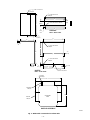 4
4
-
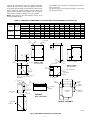 5
5
-
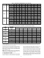 6
6
-
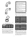 7
7
-
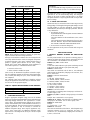 8
8
-
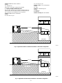 9
9
-
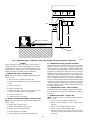 10
10
-
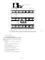 11
11
-
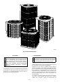 12
12
-
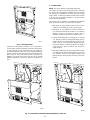 13
13
-
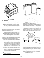 14
14
-
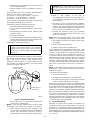 15
15
-
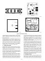 16
16
-
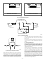 17
17
-
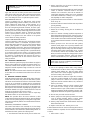 18
18
-
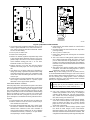 19
19
-
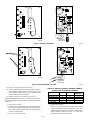 20
20
-
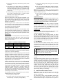 21
21
-
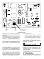 22
22
-
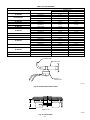 23
23
-
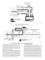 24
24
-
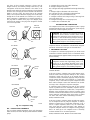 25
25
-
 26
26
-
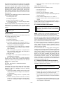 27
27
-
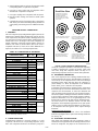 28
28
-
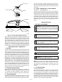 29
29
-
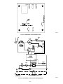 30
30
-
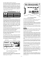 31
31
-
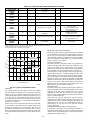 32
32
-
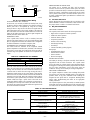 33
33
-
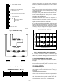 34
34
-
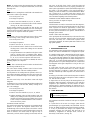 35
35
-
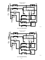 36
36
-
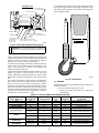 37
37
-
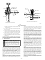 38
38
-
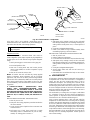 39
39
-
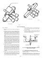 40
40
-
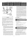 41
41
-
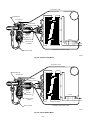 42
42
-
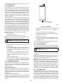 43
43
-
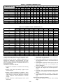 44
44
-
 45
45
-
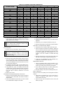 46
46
-
 47
47
-
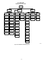 48
48
-
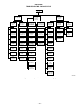 49
49
-
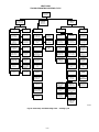 50
50
-
 51
51
-
 52
52


Ask a question and I''ll find the answer in the document
Finding information in a document is now easier with AI
Related papers
Other documents
-
Broan Liquid Line Solenoid Kits Installation guide
-
-
Fedders CH48ACD1 User manual
-
Carrier 38CKW Installation And Start-Up Instructions Manual
-
-
-
Carrier 38YSA User manual
-
-
-
COMFORT-AIRE HRG1442S1M-CY Operating instructions