
i
Motherboard User’s Guide
This publication, including photographs, illustrations and software, is under the
protection of international copyright laws, with all rights reserved. Neither this
guide, nor any of the material contained herein, may be reproduced without the
express written consent of the manufacturer.
The information in this document is subject to change without notice. The
manufacturer makes no representations or warranties with respect to the
contents hereof and specifically disclaims any implied warranties of merchant-
ability or fitness for any particular purpose. Further, the manufacturer reserves
the right to revise this publication and to make changes from time to time in the
content hereof without obligation of the manufacturer to notify any person of
such revision or changes.
Trademarks
Microsoft, MS-DOS and Windows are registered trademarks of Microsoft Corp.
AMD, Athlon, Sempron and Duron are registered trademarks of AMD Corp.
Other names used in this publication may be trademarks and are acknowledged.
Static Electricity Precautions
1. Don’t take this motherboard and components out of their original static-
proof package until you are ready to install them.
2. While installing, please wear a grounded wrist strap if possible. If you
don’t have a wrist strap, discharge static electricity by touching the bare
metal of the system chassis.
3. Carefully hold this motherboard by its edges. Do not touch those
components unless it is absolutely necessary. Put this motherboard on
the top of static-protection package with component side facing up
while installing.
Pre-Installation Inspection
1. Inspect this motherboard whether there are any damages to components
and connectors on the board.
2. If you suspect this motherboard has been damaged, do not connect
power to the system. Contact your motherboard vendor about those
damages.
Copyright © 2011
All Rights Reserved
A45G Series, V1.0
September, 2011

ii
Motherboard User’s Guide
Table of Contents
Trademark ............................................................................................................i
Chapter 1: Introduction ..................................................................................... 1
Key Features .................................................................................................................... 1
Package Contents ........................................................................................................... 4
Chapter 2: Motherboard Installation .............................................................. 5
Motherboard Components.................................................................................. 6
Installing the Processor ................................................................................................. 7
Installing Memory Modules .......................................................................................... 9
Jumper Settings ............................................................................................................ 1 0
Install the Motherboard ............................................................................................... 11
Connecting Optional Devices .....................................................................................1 2
Install Other Devices .................................................................................................... 1 5
Expansion Slots ............................................................................................................ 1 6
Chapter 3: BIOS Setup Utility ....................................................................... 18
Introduction .................................................................................................................. 1 8
Running the Setup Utility...................................................................................18
Standard CMOS Setup Page .......................................................................................1 9
Advanced Setup Page .................................................................................................. 2 0
Advanced Chipset Setup Page .................................................................................... 2 2
Integrated Peripherals Page ....................................................................................... 2 3
Power Management Setup Page ................................................................................2 5
PCI/PnP Setup Page .................................................................................................... 2 6
PC Health Status Page ................................................................................................ 2 6
Frequency/Voltage Control Page ...............................................................................2 9
Load Default Settings ...................................................................................................3 0
Supervisor Password Page .......................................................................................... 3 0
User Password Page ....................................................................................................3 1
Save & Exit Setup ......................................................................................................... 3 1
Exit Without Saving ...................................................................................................... 3 1
Chapter 4: Software & Applications .............................................................. 32
Introduction .................................................................................................................. 3 2
Installing Support Software ........................................................................................3 2
Bundled Software Installation .................................................................................... 3 4
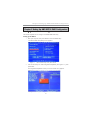
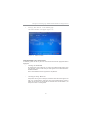
Chapter 5: Setting Up AMD SB710 RAID Configuration ........................... 35
Setting Up a bootable RAID Array ............................................................................ 3 5

iii
Motherboard User’s Guide
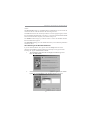
Notice:
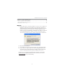
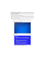
1. Owing to Microsoft’s certifying schedule is various to every supplier, we
might have some drivers not certified yet by Microsoft. Therefore, it
might happen under Windows XP that a dialogue box (shown as below)
pops out warning you this software has not passed Windows Logo
testing to verify its compatibility with Windows XP. Please rest assured
that our RD department has already tested and verified these drivers.
Just click the “Continue Anyway” button and go ahead the installation.
2. USB 2.0 Driver Limitations:
2-1. The USB 2.0 driver only supports Windows XP and Windows 2000.
2-2. If you connect a USB 2.0 hub to the root hub, plugging USB devices
into this hub, the system might not successfully execute certain USB
devices’ connection because it could not recognize these devices.
Currently, we are working on such limitations’ solution. As soon as the
olution is done, the updated USB drive will be released to our website:
www.pcchips.com for your downloading.
Chapter 6: Trouble Shooting Tips ................................................................. 43
Start up problems during assemly ..............................................................................43
Start up problems after prolong use .......................................................................... 4
4
Maintenance and care tips .......................................................................................... 4
4

1
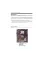
Motherboard User’s Guide
Chapter 1 Introduction
This motherboard is a high performance, enhanced function motherboard that sup-
ports socket AM3 for AMD Phenom
TM
II/Athlon II/Sempron processors for high-
end business or personal desktop markets.
This motherboard is based on AMD RS780L Northbridge (NB) and SB710 Sout-
hbridge (SB) chipsets. The Northbridge supports the HyperTransport
TM
3.0
interface. The memory controller supports DDR3 memory DIMM frequencies
of 1333/1066/800. It supports two DDR3 sockets with maximum memory size
of 8 GB. High resolution graphics via one PCI Express x16 slot.
The SB710 Southbridge supports two PCI slots which are PCI 2.3 compliant. In
addition, one PCI Express x1 slot is supported, fully compliant to the PCI Expr-
ess Base Specification, Revision 1.1. It integrats USB 2.0 interface, supporting
up to eight functional ports (4 USB 2.0 ports and 2 USB 2.0 headers support
additional 4 USB 2.0 ports). One onboard IDE connector supports two IDE de-
vices in Ultra ATA 133/100/66/33 modes. The Southbridge integrates a Serial
ATA host controller, supporting four SATA ports with maximum transfer rate
up to 3.0 Gb/s each. It provides AMD SATA RAID configuration with RAID 0,
1 and 10 modes supported.
There is an advanced full set of I/O ports in the rear panel, including PS/2 mouse
and keyboard connectors, VGA, four USB 2.0 ports, one LAN port and audio
jacks for microphone, line-in and line-out. This motherboar- d is designed in a
Micro ATX form factor using a four-layer printed circuit board and measures
244 mm x 180 mm.
Note: This board supports CPU up to 95W TDP only.
Key Features
The key features of this motherboard include:
Socket-AM3 Processor Support
• Accommodates AMD Phenom
TM
II/Athlon II/Sempron processors
• Supports HyperTransport
TM
(HT) 3.0 interface Speeds
HyperTransport
TM
technology is a point-to-point link between two devices, it
enables integrated circuits to exchange information at much higher speeds than
currently available interconnect technologies.

2
Motherboard User’s Guide
Chipset
The AMD RS780L Northbridge (NB) and SB710 Southbridge (SB) chipset are
based on an innovative and scalable architecture with proven reliability and per-
formance.
• One x 4 A-Link Express II interface (PCI Express 1.1 compliant) for con-
nection to an AMD Southbridge
• Supports one PCI Express x16 for Graphics Interface, fully compliant to
the PCI Express Base Specification revision 1.1
• Fully supports ACPI states S0, S1, S2, S3, S4 and S5
• Single chip solution in 80nm, 1.2 V CMOS technology
• Compliant with PCI v2.3 interface at 33 MHz
• Supports four Serial ATA devices which speeds up to 3.0Gb/s
• Integrated USB 2.0 Host Controller supporting up to eight USB 2.0
ports
• Integrated IDE controller supports Ultra ATA 133/100/66/33 modes
• Supports integrated RAID0, RAID1 and RAID10 (requires use of 4 or
more SATA ports) functionalities across all 4 ports
Expansion Slots
• One PCI Express x16 slot
• One PCI Express x 1 slot
• Two 32-bit PCI v2.3 complianat slots
Memory Support
• DDR3 1333/1066/800 DDR3 SDRAM with Dual-
channel supported
• Accommodates two unbuffered DIMMs
• 2 x 240-pin DDR3 DIMM sockets support up to 8 GB
Onboard IDE channels
• One IDE Connector
• Supports PIO (Programmable Input/Output) and DMA (Direct
MemoryAccess) modes
• Supports IDE Ultra DMA bus mastering with transfer rates of 133/100/
66MB/sec
Serial ATA
• Four Serial ATA Connectors
• Transfer rate exceeding best ATA (~3.0 Gb/s) with scalability to higher
rates
• Low pin count for both host and devices

3
Chapter 1: Introduction
BIOS Firmware
The motherboard uses AMI BIOS that enables users to configure many
system features including the following:
• Power management
• Wake-up alarms
• CPU parameters
• CPU and memory timing
The firmware can also be used to set parameters for different processor clock
speeds.
Onboard I/O Ports
• Two PS/2 ports for mouse and keyboard
• One VGA port
• Four back-panel USB 2.0 ports
• One LAN port
• Audio jacks for microphone, line-in and ine-out
Audio (VIA VT1705 CODEC)
• 5.1 Channel High Definition Audio Codec
• Exceeds Microsoft Windows Logo Program (WLP) Requirements
• ADCs supports 44.1k/48k/88.2k/96k/192kHz sample rate
• Power Support: Digital: 3.3V; Analog: 5.0V
Onboard LAN (optional)
• Supports PCI Express
TM
1.1
• Integrated 10/100 transceiver
• Wake-on-LAN and remote wake-up support
• Supports PCI Express
TM
1.1
• Integrated 10/100/1000 transceiver
• Wake-on-LAN and remote wake-up support
Dimensions
• Micro ATX form factor of 244 x 180 mm
Note: Hardware specifications and software items are subject to change with
out notification.

4
Motherboard User’s Guide
Package Contents
Your motherboard package ships with the following items:
The motherboard
Two Serial ATA cables
The Software support disk
Optional Accessories
You can purchase the following optional accessories for this motherboard.
The Extended USB module
The Serial ATA cable
Note: You can purchase your own optional accessories from the third party,
but please contact your local vendor on any issues of the specification
and compatibility.

5
Chapter 2: Motherboard Installation
Chapter 2 Motherboard Installation
To install this motherboard in a system, please follow these instructions in this
chapter:
Identify the motherboard components
Install a CPU
Install one or more system memory modules
Make sure all jumpers and switches are set correctly
Install this motherboard in a system chassis (case)
Connect any extension brackets or cables to headers/connectors on the
motherboard
Install peripheral devices and make the appropriate connections to
headers/connectors on the motherboard
Note:
1 Before installing this motherboard, make sure jumper CLR_CMOS is
under Normal setting. See this chapter for information about locating
CLR_CMOS and the setting options.
2 Never connect power to the system during installation; otherwise, it
may damage the motherboard.

6
Motherboard User’s Guide
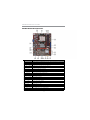
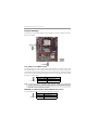
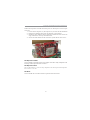
Motherboard Components
LABEL COMPONENTS
1. CPU SOCKET
Socket AM3 for AMD Phenom
TM
II /Athlon II/Sempron processors
2. CPU_FAN CPU cooling fan connector
3. DDR3_1~2 240-pin DDR3 SDRAM slots
4. ATX_POWER Standard 24-pin ATX power connector
5. IDE Primary IDE connector
6. SYS_FAN System cooling fan connector
7. SATA1~4 Serial ATA connectors
8.USBPWR_F1 Front panel USB power select jumper
9. F_PANEL Front panel switch/LED header
10.F_USB1~2 Front Panel USB headers
11.SPK Speaker header
12.CLR_CMOS Clear CMOS jumper
13.COM Onboard serial header
14.LPT Parallel port header
15.F_AUDIO Front panel audio header
16.PCI1~2 32-bit add-on card slots
17.PCIEX1 PCI Express x1 slot
18.CASE Chassis detect jumper
19.PCIEX16 PCI Express x16 slot for graphics interface
20.USBPWR_R1 Rear USB/PS2 power select jumper
21.ATX12V 4-pin +12V power connector

7
Chapter 2: Motherboard Installation
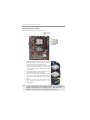
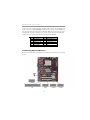
Installing the Processor
This motherboard has a socket AM3 processor socket. When choosing a processor,
consider the performance requirements of the system. Performance is based on the
processor design, the clock speed and system bus frequency of the processor, and
the quantity of internal cache memory and external cache memory.
PS/2 Mouse
Use the upper PS/2 port to connect a PS/2
pointing device.
PS/2 Keyboard
Use the lower PS/2 port to connect a PS/2
keyboard.
VGA P o rt
Connect your monitor to the VGA port.
LAN Port
Connect an RJ-45 jack to the LAN port
to connect your computer to the Network.
USB Ports
Use the USB ports to connect USB devices.
Audio P ort s
Use the three audio ports to connect audio
devices. T he first jack is for stereo line-in
signal. The t hird jack is for microphone.

8
Motherboard User’s Guide
CPU Installation Procedure
Follow these instructions to install the CPU:
1 Unhook the locking lever of the CPU socket.
Pull the locking lever away from the socket
and raising it to the upright position.
2 Match the pin1 corner marked as the beveled
edge on the CPU with the pin1 corner on the
socket. Insert the CPU into the socket. Do
not use force.
3 Push the locking lever down and hook it un-
der the latch on the edge of socket.
4 Apply thermal grease to the top of the CPU.
5 Install the cooling fan/heatsink unit onto the
CPU, and secure them all onto the socket
base.
6 Plug the CPU fan power cable into the CPU
fan connector (CPU_FAN1) on the
motherboard.
Note: To achieve better airflow rates and heat dissipation, we suggest that
you use a high quality fan with 4800 rpm at least. CPU fan and heatsink
installation procedures may vary with the type of CPU fan/heatsink
supplied. The form and size of fan/heatsink may also vary.

9
Chapter 2: Motherboard Installation
Installing Memory Modules
This motherboard accommodates two 240-pin DIMM sockets (Dual Inline Memory
Module) for unbuffered DDR3 1333/1066/800 memory modules (Double Data
Rate SDRAM), and maximum 8 GB installed memory.
Memory Module Installation Procedure
These modules can be installed with up to 8 GB system memory. Refer to the
following to install the memory module.
1. Push down the latches on both sides of the DIMM socket.
2. Align the memory module with the socket. There is a notch on the DIMM
socket that you can install the DIMM module in the correct direction.
Match the cutout on the DIMM module with the notch on the DIMM
socket.
3. Install the DIMM module into the socket and press it firmly down until it
is seated correctly. The socket latches are levered upwards and latch on to
the edges of the DIMM.
4. Install any remaining DIMM modules.

10
Motherboard User’s Guide
CLR_CMOS: Clear CMOS Jumper
Use this jumper to clear the contents of the CMOS memory. You may need to clear
the CMOS memory if the settings in the Setup Utility are incorrect and prevent
your motherboard from operating. To clear the CMOS memory, disconnect all the
power cables from the motherboard and then move the jumper cap into the CLEAR
setting for a few seconds.
Jumper Settings
Connecting two pins with a jumper cap is SHORT; removing a jumper cap from
these pins, OPEN.
Note: To avoid the system unstability after clearing CMOS, we recommend
users to enter the main BIOS setting page to “Load Optimal De-faults”
and then “Save Changes and Exit”.
Function Jumper Setting
VCC Short Pins 1-2
5VSB Short Pins 2-3
USBPWR_R1
1
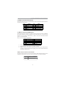
Use this jumper to set the Front Panel USB Power function.
USBPWR_R1: FRONT PANEL USB POWER SELECT Jumper
Function Jumper Setting
NORMAL CMOS Short Pins 1-2
CLEAR Short Pins 2-3
1
CLR_CMOS

11
Chapter 2: Motherboard Installation
Install The Motherboard
Install the motherboard in a system chassis (case). The board is a Micro ATX size
motherboard. You can install this motherboard in an ATX case. Make sure your
case has an I/O cover plate matching the ports on this motherboard.
Install the motherboard in a case. Follow the case manufacturer’s instructions to
use the hardware and internal mounting points on the chassis.
Note: 1. Make sure the power supply provides enough SB5V voltage before
selecting the SB5V function.
2. To wake up the computer by USB/PS2 KB/Mouse in S3 status, users
have to place the USBPWR_F & USBPWR_R cap onto 2-3 pin instead of
1-2 as default, and then press into BIOS “power Management Setup”
page to choose the functions (USB/PS2KB/MS) you want to enable.
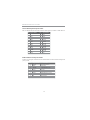
USBPWR_F1
1
Function Jumper Setting
VCC Short Pins 1-2
5VSB Short Pins 2-3
USBPWR_F1: REAR USB PS/2 POWER SELECT Jumper
Use this jumper to set the Rear USB PS/2 Power function.

12
Motherboard User’s Guide
Connecting Optional Devices
Refer to the following for information on connecting the motherboard’s optional
devices:
Connect the CPU cooling fan cable to CPU_FAN. Connect the standard power
supply connector to ATX_POWER. Connect the case speaker cable to SPK. Con-
nect the cable from the cooling fan to the SYS_FAN fan power connector on the
motherboard. Connect the auxiliary case power supply connector to ATX_12V.
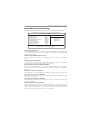
Connect the case switches and indicator LEDs to the F_PANEL.
Pin Signal Pin Signal
1 HD_L ED_ P( + ) 2 FP PW R/ SL P( + )
3 HD_LED_N(- ) 4 FP PWR/SLP(- )
5 RES ET_ SW_ N( - ) 6 POW ER_S W_P( +)
7 RES ET_ SW_ P( +) 8 POWER_ SW_ N( - )
9 RSV D_DNU 10 KEY

13
Chapter 2: Motherboard Installation
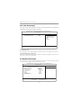
F_AUDIO: Front Panel Audio Header
This header allows the user to install auxiliary front-oriented microphone and line-
out ports for easier access.
Here is a list of USB pin assignments.
1. Locate the F_USB1~2 headers on the motherboard.
2. Plug the bracket cable onto the F_USB1~2 headers.
3. Remove a slot cover from one of the expansion slots on the system chassis.
Install an extension bracket in the opening. Secure the extension bracket to
the chassis with a screw.
Pin Signal Pin Signal
1 V ERG _FP_ USB PWR0 2 V ERG _F P_US BPW R0
3 USB_FP_P0(-) 4 USB_FP_P1(- )
5 USB_FP_P0(+) 6 USB_FP_P1(+)
7 GROUND 8 GROUND
9KEY 10GROUND
F_USB1~2: Front Panel USB Headers
The motherboard has USB ports installed on the rear edge I/O port array. Addition-
ally, some computer cases have USB ports at the front of the case. If you have this
kind of case, use auxiliary USB headers F_USB1~2 to connect the front-mounted
ports to the motherboard.
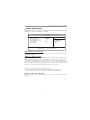
CASE: Chassis intrusion detect header
This detects if the chassis cover has been removed. This function needs a chassis
equipped with instrusion detection switch and needs to be enabled in BIOS.
Pin Signal Pin Signal
1 PORT1L 2 A UD_GND
3 PORT1 R 4 PRES ENCE#
5 PORT2R 6 SENSE1_RETURN
7 SENS E_SEND 8 K EY
9 PORT2 L 1 0 SENS E2_ RETURN
Pin 1-2 Function
Short Chassis cover is removed
Open Chassis cover is closed

14
Motherboard User’s Guide
13 SLCT
26 Key
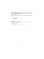
LPT: Onboard parallel port header
This is a header that can ba used to connect to the printer, scanner or other devices.
1 STROBE
14 ALF
2 PD0
3 PD1
4 PD2
5 PD3
15 ERROR
16 INIT
17 SLCTIN
18 Ground
Pin Signal Name
Pin Signal Name
6 PD4
19 Ground
7 PD5
20 Ground
8 PD6
9 PD7
10 ACK
11 BUSK
12 PE
21 Ground
22 Ground
23 Ground
24 Ground
25 Ground
COM: Onboard serial port header
Connect a serial port extension bracket to this header to add a second serial port to
your system.
1 DCDB Data Carrier Detect
2 SINB Serial Input
3 SOUTB UART B Serial Output
4 DTRB UART B Data Terminal Ready
5 GND Ground
6 DSRB Data Set Ready
7 RTSB RART B Request to Send
8 CTSB Clear to Send
9 RI Ring Indicator
10 Key No pin
Pin Signal Name Function

15
Chapter 2: Motherboard Installation
IDE Devices
IDE devices include hard disk drives, high-density diskette drives, and CD-ROM
or DVD-ROM drives, among others.
The mainboard ships with an IDE cable that can support one or two IDE devices.
If you connect two devices to a single cable, you must configure one of the drives
as Master and one of the drives as Slave. The documentation of the IDE device will
tell you how to configure the device as a Master or Slave device. The Master device
connects to the end of the cable.
Install the device(s) and connect power from the system power supply. Use the
cable provided to connect the device(s) to the Primary IDE channel connector IDE1
on the motherboard.
Install Other Devices
Install and connect any other devices in the system following the steps below.

16
Motherboard User’s Guide
Expansion Slots
This motherboard has one PCI Express x16, one PCI Express x1 and two 32-bit
PCI slots.
Serial ATA Devices
The Serial ATA (Advanced Technology Attachment) is the standard interface for
the IDE hard drives, which is designed to overcome the design limitations while
enabling the storage interface to scale with the growing media rate demands of PC
platforms. It provides you a faster transfer rate of 3.0 Gb/s. If you have installed a
Serial ATA hard drive, you can connect the Serial ATA cables to the Serial ATA hard
drive or the connector on the motherboard.
On the motherboard, locate the Serial ATA connectors SATA1-4, which support
Serial ATA devices, simpler disk drive cabling and easier PC assembly.
It eliminates limitations of the current Parallel ATA interface, but maintains register
compatibility and software compatibility with Parallel ATA.

17
Chapter 2: Motherboard Installation
Follow the steps below to install an PCI Express x16/ PCI Express x1/PCI expan-
sion card.
1. Locate the PCI Express x16, PCI Express x1, PCI slots on the mainboard.
2. Remove the blanking plate of the slot from the system chassis.
3. Install the edge connector of the expansion card into the slot. Ensure the
edge connector is correctly seated in the slot.
4. Secure the metal bracket of the card to the system chassis with a screw.
PCI Express x16 Slot
You can install an external PCI Express graphics card that is fully compliant to the
PCI Express Base Specification revsion 1.1.
PCI Express x1 Slot
The two PCI Express x1 slots are fully compliant to the PCI Express Base Specifica-
tion revision 1.1 as well.
PCI Slots
You can install the 32-bit PCI interface expansion cards in the slots.
Page is loading ...
Page is loading ...
Page is loading ...
Page is loading ...
Page is loading ...
Page is loading ...
Page is loading ...
Page is loading ...
Page is loading ...
Page is loading ...
Page is loading ...
Page is loading ...
Page is loading ...
Page is loading ...
Page is loading ...
Page is loading ...
Page is loading ...
Page is loading ...
Page is loading ...
Page is loading ...
Page is loading ...
Page is loading ...
Page is loading ...
Page is loading ...
Page is loading ...
Page is loading ...
Page is loading ...
Page is loading ...
-
 1
1
-
 2
2
-
 3
3
-
 4
4
-
 5
5
-
 6
6
-
 7
7
-
 8
8
-
 9
9
-
 10
10
-
 11
11
-
 12
12
-
 13
13
-
 14
14
-
 15
15
-
 16
16
-
 17
17
-
 18
18
-
 19
19
-
 20
20
-
 21
21
-
 22
22
-
 23
23
-
 24
24
-
 25
25
-
 26
26
-
 27
27
-
 28
28
-
 29
29
-
 30
30
-
 31
31
-
 32
32
-
 33
33
-
 34
34
-
 35
35
-
 36
36
-
 37
37
-
 38
38
-
 39
39
-
 40
40
-
 41
41
-
 42
42
-
 43
43
-
 44
44
-
 45
45
-
 46
46
-
 47
47
-
 48
48


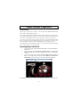
Ask a question and I''ll find the answer in the document
Finding information in a document is now easier with AI
Related papers
-
PC CHIPS P65G Datasheet
-
-
PC CHIPS P53G (V1.0) User manual
-
-
ECS P49G (V1.0) User manual
-
-
-
-
-