ECS A880GM-AD3 User manual

Category
Motherboards
Type
User manual
Preface
Preface
Copyright
This publication, including all photographs, illustrations and software, is protected
under international copyright laws, with all rights reserved. Neither this manual, nor
any of the material contained herein, may be reproduced without written consent of
the author.
Version 1.0
Disclaimer
The information in this document is subject to change without notice. The manufac-
turer makes no representations or warranties with respect to the contents hereof and
specifically disclaims any implied warranties of merchantability or fitness for any
particular purpose. The manufacturer reserves the right to revise this publication and
to make changes from time to time in the content hereof without obligation of the
manufacturer to notify any person of such revision or changes.
Federal Communications Commission (FCC)
This equipment has been tested and found to comply with the limits for a Class B
digital device, pursuant to Part 15 of the FCC Rules. These limits are designed to
provide reasonable protection against harmful interference in a residential installa-
tion. This equipment generates, uses, and can radiate radio frequency energy and, if
not installed and used in accordance with the instructions, may cause harmful inter-
ference to radio communications. However, there is no guarantee that interference
will not occur in a particular installation. If this equipment does cause harmful
interference to radio or television reception, which can be determined by turning the
equipment off and on, the user is encouraged to try to correct the interference by one
or more of the following measures:
Reorient or relocate the receiving antenna.
Increase the separation between the equipment and the receiver.
Connect the equipment onto an outlet on a circuit different from that to
which the receiver is connected.
Consult the dealer or an experienced radio/TV technician for help.
Shielded interconnect cables and a shielded AC power cable must be employed with
this equipment to ensure compliance with the pertinent RF emission limits govern-
ing this device. Changes or modifications not expressly approved by the system’s
manufacturer could void the user’s authority to operate the equipment.
Trademark Recognition
Microsoft, MS-DOS and Windows are registered trademarks of Microsoft Corp.
AMD, Phenom, Athlon, Sempron and Duron are registered trademarks of AMD
Corporation.
Other product names used in this manual are the properties of their respective
owners and are acknowledged.
ii
Preface
Declaration of Conformity
This device complies with part 15 of the FCC rules. Operation is subject to the
following conditions:
This device may not cause harmful interference, and
This device must accept any interference received, including interfer-
ence that may cause undesired operation.
Canadian Department of Communications
This class B digital apparatus meets all requirements of the Canadian Interference-
causing Equipment Regulations.
Cet appareil numérique de la classe B respecte toutes les exigences du Réglement sur
le matériel brouilieur du Canada.
About the Manual
The manual consists of the following:
Chapter 1
Introducing the Motherboard
Describes features of the motherboard.
Go to
H
page 1
Describes installation of motherboard
components.
Go to
H
page 7
Provides information on using the BIOS
Setup Utility.
Go to
H
page 27
Describes the motherboard software
Go to
H
page 45
Chapter 2
Installing the Motherboard
Chapter 3
Using BIOS
Chapter 4
Using the Motherboard Software
Go to
Chatper 7
Setting Up eJIFFY
Describes the eJIFFY setting up
Go to
H
page 61
Chatper 8
Trouble Shooting
Provides basic trouble shooting tips
page 71Go to
H
page 49
Chapter 5
Hybrid Graphics
®
Technology
Support
Describes the Hybrid Graphics
®
Technol-
ogy
Go to
H
Chapter 6
Setting Up AMD SB710 RAID Con-
figuration
Describes the AMD SB710 RAID
Configuration
H
page 53
iii
TT
TT
T
ABLE OF CONTENTSABLE OF CONTENTS
ABLE OF CONTENTS
Preface i
Chapter 1 1
Introducing the Motherboard 1
Introduction............................................................................................1
Feature.....................................................................................................2
Specifications.........................................................................................5
Motherboard Components...................................................................6
Chapter 2
77
77
7
Installing the Motherboard 7
Safety Precautions...............................................................................7
Choosing a Computer Case..................................................................7
Installing the Motherboard in a Case.................................................7
Checking Jumper Settings....................................................................8
Setting Jumpers...............................................................................8
Checking Jumper Settings...............................................................9
Jumper Settings...............................................................................9
Installing Hardware...........................................................................10
Installing the Processor.................................................................10
Installing Memory Modules...........................................................11
Expansion Slots.............................................................................15
Connecting Optional Devices........................................................17
Installing a Hard Disk Drive/CD-ROM/SATA Hard Drive............20
Installing a Floppy Diskette Drive................................................21
Connecting I/O Devices......................................................................22
Connecting Case Components...........................................................23
Front Panel Header.......................................................................25
Chapter 3
27 27
27 27
27
Using BIOS 27
About the Setup Utility....................................................................27
The Standard Configuration..........................................................27
Entering the Setup Utility...............................................................27
Resetting the Default CMOS Values...............................................28
Using BIOS............................................................................................29
Standard CMOS Setup..................................................................30
Advanced Setup.............................................................................32
Advanced Chipset Setup................................................................33
iv
Integrated Peripherals.................................................................34
Power Management Setup.............................................................35
PCI/PnP Setup..............................................................................36
PC Health Status..........................................................................37
M.I.B.II (MB Intelligent BIOS II).................................................39
Load Default Settings....................................................................42
Supervisor Password.....................................................................42
User Password..............................................................................43
Save & Exit Setup .........................................................................43
Exit Without Saving.......................................................................43
Updating the BIOS........................................................................44
Chapter 4
45 45
45 45
45
Using the Motherboard Software 45
About the Software DVD-ROM/CD-ROM.................................45
Auto-installing under Windows XP/Vista/7...............................45
Running Setup...............................................................................46
Manual Installation......................................................................48
Utility Software Reference............................................................48
Chapter 7
61 61
61 61
61
Setting Up eJIFFY 61
Introduction....................................................................................61
Installation and BIOS Setup..............................................................62
Entering eJIFFY..........................................................................................65
Features Icons..............................................................................................66
Usage FAQ...................................................................................................67
Chapter 8
71 71
71 71
71
Trouble Shooting 71
Start up problems during assembly..................................................71
Start up problems after prolong use................................................71
Maintenance and care tips.................................................................72
Basic Troubleshooting Flowchart....................................................73
Chapter 5
49 49
49 49
49
Hybrid Graphics
®
Technology Support 49
Hybrid Graphics
®
Technology.....................................................49
Chapter 6
53 53
53 53
53
Setting Up AMD SB710 RAID Configuration 53
Setting Up a Bootable RAID Array................................................53
1
Introducing the Motherboard
Chapter 1
Introducing the Motherboard
Introduction
*1. Due to AMD CPU spec limitation, please refer to Memory QVL for more
information.
Thank you for choosing the A880GM-AD3 motherboard. This motherboard is a
high performance, enhanced function motherboard that supports socket for AM3
Phenom
TM
II/Athlon
TM
II/ Sempron
TM
processors for high-end business or personal
desktop markets.
The motherboard incorporates the AMD 880G Northbridge (NB) and SB710
Southbridge (SB) chipsets. The Northbridge supports the HyperTransport
TM
3.0 in-
terface. The memory controller supports DDR3 memory DIMM frequencies of
1600 (OC)/1333/1066/800
*1
. It supports four DDR3 slots with maximum memory
size of 32 GB
*2
. One PCI Express x16 slot, intended for Graphics Interface, are fully
compliant to the PCI Express (version 2.0). In addition, two PCI Express x1 slots
are supported.
The SB710 Southbridge supports three PCI slot which is PCI v2.3 compliant. It
integrates USB 2.0 interface, supporting up to twelve functional ports (six USB ports
and three USB 2.0 headers support additional six USB ports). One onboard IDE
connector supports two IDE devices in Ultra ATA 133/100/66 modes. The Southbridge
integrates a Serial ATA host controller, supporting five SATA ports with maximum
transfer rate up to 3.0 Gb/s each. It provides AMD SATA RAID configuration with
RAID 0, 1 and 10 modes supported.
There is an advanced full set of I/O ports in the rear panel, including one DVI port, one
VGA port, one LAN port, one eSATA port, one optical SPDIFO port, six USB ports,
and audio jacks for microphone, line-in and 8-channel line-out.
*2. Due to the DRAM maximum size is 4GB at present, the memory maxi-
mum size we have tested is 16GB.
In addition, this motherboard comes with a power on button, a reset button and a
CLR_CMOS button. The processor can be overclocked when CPU Over-clocking
Func. is set to Enabled in M.I.B.II (MB Intelligent BIOS II).
2
Introducing the Motherboard
Feature
Processor
HyperTransport
TM
Technology is a point-to-point link between two devices, it
enables integrated circuits to exchange information at much higher speeds than
currently available interconnect technologies.
Accommodates AM3 Phenom
TM
II/Athlon
TM
II/ Sempron
TM
processors
Supports HyperTransport
TM
(HT) 3.0 interface speeds
Support transfer rate up to 5200 mega-transfers per second
This motherboard uses a socket AM3 that carries the following features:
Chipset
This board supports CPU up to 95W TDP only; you can refer to AMD
website to check your CPU.
Compliant with PCI 2.3 specification at 33 MHz
Supports five Serial ATA devices which speeds up to
3.0 Gb/s
Integrated USB 2.0 Host Controller supporting up to
twelve USB 2.0 ports
Integrated IDE controller supports Ultra ATA 133/100/
66 modes
Supports integrated RAID0, RAID1, and RAID 10 (re-
quires use of 4 or more SATA ports) functionalities
across all 5 ports
AMD 880G
(NB)
The AMD 880G Northbridge (NB) and SB710 Southbridge (SB) chipsets are
based on an innovative and scalable architecture with proven reliability and
performance.
SB710
(SB)
Memory
Supports DDR3 1600 (OC)/1333/1066/800 DDR3 SDRAM with Dual-
channel architecture
Accommodates four unbuffered DIMMs
4 x 240-pin DDR3 DIMM sockets support up to 32 GB*
One x4 A-Link Express III interface for connection to
an AMD Southbridge. The A-Link Express III is a propri-
etary interface developed by AMD basing on the PCI
Express technology, with additional Northbridge-
Southbridge messaging functionalities. It supports the
PCIe Gen 2 transfer rate of 5 GT/s, and is backward
compatible with the A-Link Express II interface.
Supports one PCI-Express x16 Gen2 graphics link
Supports two PCI-Express x1 slots
Fully supports ACPI states S1, S3, S4 and S5
Supports ATI Radeon HD4250 Graphics*.
Supports 16-bit up/down HyperTransport (HT) 3.0 in-
terface up to 4.4 GT/s.
* Due to the DRAM maximum size is 4GB at present, the memory maxi-
mum size we have tested is 16GB
3
Introducing the Motherboard
Onboard LAN
Audio
This motherboard supports Ultra DMA bus mastering with transfer rates of
133/100/66 MB/s.
Expansion Options
The motherboard comes with the following expansion options:
One PCI Express x16 slot for Graphics Interface
Two PCI Express x1 slots
Three 32-bit PCI v2.3 compliant slots
One IDE connector supporting up to two IDE devices
Five 7-pin SATA connectors
Integrated I/O
The motherboard has a full set of I/O ports and connectors:
One PS/2 Keyboard & PS/2 mouse
One DVI port
One VGA port
One LAN port
One eSATA port
One optical SPDIFO port
Six USB ports
Audio jacks for microphone, line-in, 8-channel line out and Optical
SPDIF Out
Onboard PCI-Express LAN controller
Supports 10/100/1000 Mbit Ethernet (optional 10/100 Ethernet only
available)
Support Wake-on-LAN and remote wake-up
All DACs support 192K/96K/48K/44.1KHz DAC sample rate
High-quality analogy differential CD input
Software selectable 2.5V/3.75V VREFOUT
Meets Microsoft WLP3.10 audio requirements
Direct Sound 3D
TM
compatible
4
Introducing the Motherboard
BIOS Firmware
1. Some hardware specifications and software items are subject to change
without prior notice.
2. Due to chipset limitation, we recommend that motherboard be operated
in the ambiance between 0 and 50°C.
The firmware can also be used to set parameters for different processor clock
speeds. And it is available to adjust the voltages of the CPU, NB and SB.
The motherboard uses AMI BIOS that enables users to configure many system
features including the following:
Power management
Wake-up alarms
CPU parameters
CPU and memory timing
5
Introducing the Motherboard
AMD 880G & AMD SB710
AM3 socket for Phenom
TM
II/Athlon
TM
II/ Sempron
TM
proces-
sors
Supports “Hyper-Threading” technology CPU
Dual-channel DDR3 1600 (OC) memory architecture
4 x 240-pin DDR3 DIMM sockets support up to 32 GB*
Supports DDR3 1600 (OC)/1333/1066/800 DDR3 SDRAM
1 x PCI Express x16 slot
2 x PCI Express x1 slots
3 x PCI slots
Supported by AMD SB710 Express Chipset
5 x Serial ATA 3.0 Gb/s Host Controllers
Supports RAID 0, 1, and 10
2 x Ultra DMA133/100/66 devices
1 x eSATA 3.0 Gb/s device
ALC888S 8-ch HD audio
Realtek8111DL GigaLAN Controller (Colay RTL8103EL 10/
100 LAN Controller
1 x PS/2 keyboard & PS/2 mouse connector
6 x USB ports
1 x DVI port
1 x VGA port
1 x eSATA port
1 x RJ45 LAN connector
1 x Optical SPDIFO port
1 x Audio port (1x Line in, 4x Line out, 1x Optical SPDIF Out)
24-pin ATX Power Supply connector, 4-pin 12V connector
1 x CPU_FAN • 1 x Power on LED (Green Light)
1 x SYS_FAN • 1 x Stand by LED (Red Light)
1 x NB_FAN
5 x SATA 3Gb/s connectors
3 x USB 2.0 headers support additional 6 USB ports
1 x Front panel header
1 x Chassis Intrusion Detect header
1 x Front panel audio header
1 x Speaker header 1 x Reset button
1 x CD in header
1 x Power on button • 1 x Clear CMOS button
Chipset
Memory
Expansion
Slots
Storage
Audio
LAN
Rear Panel I/O
Internal I/O
Connectors &
Headers
AMI BIOS with 8Mb SPI ROM
Supports Plug and Play 1.0A, APM 1.2, Multi Boot, DMI
Supports ACPI revision 3.0 specification
System BIOS
Form Factor
ATX Size, 305mm x 220mm
CPU
Specifications
Support transfer rate up to 5200 mega-transfers per sec-
ond
* Due to the DRAM maximum size is 4GB at present, the memory
maxi-mum size we have tested is 16GB
6
Introducing the Motherboard
Motherboard Components
Table of Motherboard Components
LABEL COMPONENTS
Socket for AM3 Phenom
TM
II/Athlon
TM
II/ Sem
p
ron
TM
processors
2. CPU_FAN
CPU cooling fan connector
3. DDR3_1~4
240-pin DDR3 SDRAM slots
4. ATX_POWER
Standard 24-
p
in ATX
p
ower connector
5. IDE
Primar
y
IDE connector
6. SPK
S
p
eaker header
7. CASE
Chassis detector header
8. SATA1~6
Serial ATA connectors
9. PWR_BTN
Power on button
10. F_PANEL
Front panel switch/LED header
11. RST_BTN
Reset button
12. F_USB1~3
Front panel USB headers
13. USBPWR_F1~2
Front panel USB power select jumpers
14. COM
Onboard serial port header
15. CLR_CMOS_BTN
Clear CMOS button
16. CD_IN
Analog audio input connector
17. F_AUDIO
Front panel audio header
18. PCI1~3
32-bit add-on card slots
19. PCIEX16
PCI Express x16 slot for graphics interface
20. PCIE1~2
PCI Express x1 slots
21. SYS_FAN
System cooling fan connector
22. NB_FAN Northbridge cooling fan connector
23. USBPWR_R1~2
Rear panel USB PS/2 power select jumpers
24. ATX12
V
4-pin +12V power connector
1. CPU Socket
This concludes Chapter 1. The next chapter explains how to install the motherboard.
7
Installing the Motherboard
Chapter 2
Installing the Motherboard
Safety Precautions
Follow these safety precautions when installing the motherboard
Wear a grounding strap attached to a grounded device to avoid dam-
age from static electricity
Discharge static electricity by touching the metal case of a safely
grounded object before working on the motherboard
Leave components in the static-proof bags they came in
Hold all circuit boards by the edges. Do not bend circuit boards
Choosing a Computer Case
There are many types of computer cases on the market. The motherboard complies
with the specifications for the ATX system case. Firstly, some features on the
motherboard are implemented by cabling connectors on the motherboard to indica-
tors and switches on the system case. Make sure that your case supports all the
features required. Secondly, this motherboard supports two enhanced IDE drives.
Make sure that your case has sufficient power and space for all drives that you intend
to install.
Most cases have a choice of I/O templates in the rear panel. Make sure that the I/O
template in the case matches the I/O ports installed on the rear edge of the
motherboard.
This motherboard carries an ATX form factor of 350 X 220 mm. Choose a case that
accommodates this form factor.
Installing the Motherboard in a Case
Refer to the following illustration and instructions for installing the motherboard in
a case.
Most system cases have mounting brackets installed in the case, which correspond
the holes in the motherboard. Place the motherboard over the mounting brackets
and secure the motherboard onto the mounting brackets with screws.
Ensure that your case has an I/O template that supports the I/O ports and expansion
slots on your motherboard.
8
Installing the Motherboard
Do not over-tighten the screws as this can stress the motherboard.
Checking Jumper Settings
This section explains how to set jumpers for correct configuration of the motherboard.
Setting Jumpers
Use the motherboard jumpers to set system configuration options. Jumpers with
more than one pin are numbered. When setting the jumpers, ensure that the jumper
caps are placed on the correct pins.
The illustrations show a 2-pin jumper. When
the jumper cap is placed on both pins, the
jumper is SHORT. If you remove the jumper
cap, or place the jumper cap on just one pin,
the jumper is OPEN.
This illustration shows a 3-pin jumper. Pins
1 and 2 are SHORT.
SHORT OPEN
9
Installing the Motherboard
Checking Jumper Settings & Clear CMOS Button
The following illustration shows the location of the motherboard jumpers. Pin 1 is
labeled.
Jumper Settings
1. To avoid the system unstability after clearing CMOS, we recommend
users to enter the main BIOS setting page to “Load Default Settings” and
then “Save & Exit Setup”.
2. Make sure the power supply provides enough 5VSB voltage before
selecting the 5VSB function.
3. It is required that users place the USBPWR_F1~2 & USBPWR_R1~2
cap onto 2-3 pin rather than 1-2 pin as default if you want to wake up the
computer by USB/PS2 KB/Mouse.
USB Power
Cotroller
USBPWR_F1
Jumper
Type Description
Setting (default)
2-3: 5VSB
1-2: VCC5
USBPWR_F1 3-pin
3-pin
2-3: 5VSB
1-2: VCC5
1-2: VCC5
USBPWR_F2
3-pin
2-3: 5VSB
USB Power
Cotroller
USB Power
Cotroller
NO PUSH: NORMAL
PUSH: CLEAR
CLEAR CMOS
button
CLR_CMOS_BTN
USBPWR_F2
USBPWR_R1
USBPWR_R1
USBPWR_R2
1-2: VCC5
2-3: 5VSB
USBPWR_R1
3-pin
USB Power
Cotroller
CLR_CMOS_BTN
1
1
1
1
10
Installing the Motherboard
Installing Hardware
Installing the Processor
Caution: When installing a CPU heatsink and cooling fan make sure that
you DO NOT scratch the motherboard or any of the surface-mount resis-
tors with the clip of the cooling fan. If the clip of the cooling fan scrapes
across the motherboard, you may cause serious damage to the motherboard
or its components.
This motherboard has a Socket AM3 processor socket. When choosing a processor,
consider the performance requirements of the system. Performance is based on the
processor design, the clock speed and system bus frequency of the processor, and the
quantity of internal cache memory and external cache memory.
Before installing the Processor
This motherboard automatically determines the CPU clock frequency and system bus
frequency for the processor. You may be able to change these settings by making
changes to jumpers on the motherboard, or changing the settings in the system Setup
Utility. We strongly recommend that you do not over-clock processors or other
components to run faster than their rated speed.
On most motherboards, there are small surface-mount resistors near the
processor socket, which may be damaged if the cooling fan is carelessly
installed.
Avoid using cooling fans with sharp edges on the fan casing and the clips.
Also, install the cooling fan in a well-lit work area so that you can clearly
see the motherboard and processor socket.
Warning:
1. Over-clocking components can adversely affect the reliability of the
system and introduce errors into your system. Over-clocking can perma-
nently damage the motherboard by generating excess heat in components
that are run beyond the rated limits.
2. Always remove the AC power by unplugging the power cord from the
power outlet before installing or removing the motherboard or other hard-
ware components.
Fail-Safe Procedures for Over-clocking
When end-users encounter failure after attempting over-clocking, please take
the following steps to recover from it.
1. Shut down the computer.
2. Press and hold the “Page Up Key (PgUp)” of the keyboard, and then boot the
PC up.
3. Two seconds after the PC boots up, release the “Page Up Key (PgUp)”.
4. The BIOS returns to the default setting by itself.
11
Installing the Motherboard
1 Install your CPU. Pull up the lever away from
the socket and lift up to 90-degree angle.
2 Locate the CPU cut edge (the corner with
the pin hold noticeably missing). Align and
insert the CPU correctly.
3 Press the lever down and apply thermal
grease on top of the CPU.
4 Put the CPU Fan down on the retention mod-
ule and snap the four retention legs of the
cooling fan into place.
5 Flip the levers over to lock the heat sink in
place and connect the CPU cooling Fan power
cable to the CPUFAN connector. This com-
pletes the installation.
CPU Installation Procedure
The following illustration shows CPU installation components.
To achieve better airflow rates and heat dissipation, we suggest that you
use a high quality fan with 4800 rpm at least. CPU fan and heatsink
installation procedures may vary with the type of CPU fan/heatsink sup-
plied. The form and size of fan/heatsink may also vary.
Installing Memory Modules
This motherboard accommodates four memory modules. It can support four 240-pin
DDR3 1600 (OC)/1333/1066/800. The total memory capacity is 32 GB*.
DDR3 SDRAM memory module table
Do not remove any memory module from its antistatic packaging until
you are ready to install it on the motherboard. Handle the modules only
by their edges. Do not touch the components or metal parts. Always
wear a grounding strap when you handle the modules.
You must install at least one module in any of the four slots. Each module can be
installed with 8 GB of memory.
Memory module Memory Bus
DDR3 800 400 MHz
DDR3 1066 533 MHz
DDR3 1333 667 MHz
DDR3 1600 800 MHz
* Due to the DRAM maximum size is 4GB at present, the memory maxi-
mum size we have tested is 16GB
12
Installing the Motherboard
Installation Procedure
Refer to the following to install the memory modules.
1 This motherboard supports unbuffered DDR3 SDRAM only.
2 Push the latches on each side of the DIMM slot down.
3 Align the memory module with the slot. The DIMM slots are keyed with
notches and the DIMMs are keyed with cutouts so that they can only be
installed correctly.
4 Check that the cutouts on the DIMM module edge connector match the
notches in the DIMM slot.
5 Install the DIMM module into the slot and press it firmly down until it
seats correctly. The slot latches are levered upwards and latch on to
the edges of the DIMM.
6 Install any remaining DIMM modules.
For best performance and compatibility, we recommend that users install
DIMMs in the sequence of DIMM3, DIMM4, DIMM1 and DIMM2.
Recommend configuration for best performance and compatibility
Number of DIMMs DIMM 1 DIMM 2 DIMM 3 DIMM 4 AM2 AM2+ *
1
Single Channel
Unganged Mode
2
Dual Channel
Ganged Mode
3
Single Channel
Unganged Mode
4
Dual Channel
Ganged Mode
: operation with normal performance
: operation with the best performance
13
Installing the Motherboard
Table A: DDR3 (memory module) QVL (Qualified Vendor List)
The following DDR3 2100/1800/1600 (OC)/1333/1066 memory modules have been
tested and qualified for use with this motherboard.
DDR3 800
NO. Vendor Module part number IC Brand IC Chip Number SS/DS Size
1 Qimonda IMSH51U03A1F1C-08E Qimonda IDSH51-03A1F1C-OBE SS 512MB
NO. Vendor Module part number IC Brand IC Chip Number SS/DS Size
1 Elixir M2Y2G64CB8HC9N-BE DS 2GB
2 Elixir M2Y2G64CB8HC5N-BE elixir N2CB1G80CN-BE DS 2GB
3 Elpida PC3-8500U-7-00-AP Elpida J53088ASE-AC-E SS 512MB
4 Hynix HYMT112U64ZNF8-G8 AA Hynix HY5TQ1G831ZNFP-G8 SS 1GB
5 Hynix HMT112U6AFP8C-G7N0 AA Hynix H5TQ1G83AFP G7C SS 1GB
6 Hynix HYMT125U64ZNF8-G8 AA Hynix HY5TQ1G831ZN FP-G8 DS 2GB
7 Hynix HMT125U6AFP8C-G7N0 AA Hynix H5TQ1G83AFP G7C DS 2GB
8 Kingston KVR1066D3N7 Elpida J5308BASE-AE-E 07500W220 SS 1GB
9 Micron MT8JTF12864AY-1G1D1 Micron 7UD22D9JNL SS 1GB
10 Micron MT8JTF12864AY-1G1D1 Micron 8TD22 D9JNL SS 1GB
11 Micron MT16JTF25664AY-1G1D1 Micron 7UD22D9JNL DS 2GB
12 Micron MT16JTF25664AY-1G1D1 Micron 8WD22 D9JNL DS 2GB
13 Micron MT16JTF25664AZ-1G1F1 Micron 9EF22 D9KPV DS 2GB
14 Micron MT8JTF12864AZ-1G1F1 Micron 9NF22 D9KPT SS 1GB
15 Ramaxel RMR1810NA48E7F-1066-LF NANYA NT5CB128H8AN-DE SS 1GB
16 Samsung M378B2873DZ1-CF8 0818 SEC HCF8 K4B1G0846D SS 1GB
17 Samsung M378B5673DZ1-CF8 0842 SEC K4B1G0846D HCF8 DS 2GB
18 Kingston KVR1066D3N7/512
Elpida
J5308BASE-AE-E 07340W065
SS 512MB
19 Qimonda IMSH1GU03A1F1C-10F Qimonda IDSH1G-03A1F1C-10F FSS15085 SS 1GB
20 Qimonda IMSH1GU03A1F1C-10G Qimonda IDSH1G-03A1F1C-10G FSS14526 SS 1GB
21 Qimonda IMSH2GU13A1F1C-10F Qimonda IDSH1G-03A1F1C-10F FSS15085 DS 2GB
22 Qimonda IMSH2GU13A1F1C-10G Qimonda IDSH1G-03A1F1C-10G FSS13467 DS 2GB
23 Hynix HYMT112U64ZNF8-G8 AA
Hynix HY5TQ1G831ZN FP-G8
SS 1GB
24 Samsung M378B2873EH1-CF8 SEC HCF8K4B1G0846E SS 1GB
25 Samsung M378B5673DZ1-CF8 0842 SEC K4B1G0846D HCF8 DS 2GB
26 Aeneon AEH760UD00-10FA98
X
Aeneon AEH93R10F 0737 SS 1GB
27 Elpida EBJ10UE8BDF0-AE-F Elpida J1108BDSE-DJ-F SS 1GB
28 Elpida EBJ21UE8BDF0-AE-F Elpida J1108BDSE-DJ-F DS 2GB
29 Corsair CM3X1024-1066C7 SS 1GB
30 Nanya M2Y2G64TU8HD5B-BD elixir N2CB1G80AN-CG DS 2GB
31 Winchip 64A0TPHM8G17E
Elpida J5308BASE-AC-E
SS 1GB
DDR3 1066
14
Installing the Motherboard
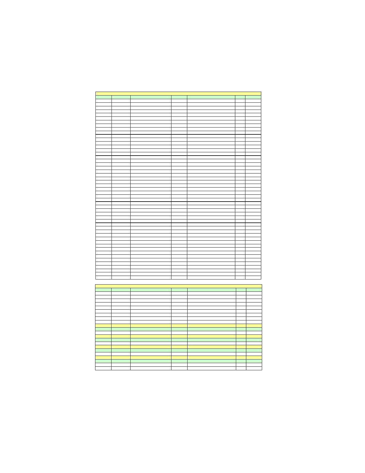
NO. Vend or Module part number IC Brand IC Chip Number SS/DS Size
1 A-DATA AD3U1333B1G9-B Hynix H5TQ1G83BFR SS 1GB
2 A-DATA AD3U1333B2G9-B Hynix H5TQ1G83BFR DS 2GB
3Apace
r
78.A1GC6.9L1 Apace
r
AM5D5808ADWSBG DS 2GB
4 Elixir M2F2G64CB8HA4N-CG Elixir N2CB1G80AN-CG 0903 DS 2GB
5 Elixir M2Y2G64CB8HC9N-CG DS 2GB
6 Hynix HMT112U6AFP8C-H9N0 AA Hynix H5TQ1G83AFP H9C SS 1GB
7 Hynix HMT125U6AFP8C-H9N0 AA Hynix H5TQ1G83AFP H9C DS 2GB
8 G.SKILL F3-10666CL9D-4GBRL DS 2GB
9 G.SKILL F3-10666CL8D-4GBECO DS 2GB
10 G.SKILL F3-10666CL9D-4GBNQ DS 2GB
11 Kingston KVR1333D3N9 Elpida J1108BASE-DJ-E SS 1GB
12 Kingston KVR1333D3N9 Elpida J1108BABG-DJ-E DS 2GB
13 Kingston KVR1333D3N9 Hynix Hynix/H5TQ2G83AFR DS 4GB
14 KingMax FLFD45F-B8KG9 NAES KingMax KFB8FNGXF-ANX-15A SS 1GB
15 KingMax FLFE85F-B8KG9 NEES KingMax KFB8FNGXF-ANX-15A DS 2GB
16 Nanya NT2GC64B8HAONF-CG Elixir N2CB1G80AN-CG DS 2GB
17 Micron MT8JTF12864AY-1G4D1 Micron 8UD22 D9JNM SS 1GB
18 Micron MT16JTF25664AY-1G4D1 Micron 8WD22 D9JNM DS 2GB
19 Micron MT8JTF12864AZ-1G4F1 Micron 9MF22 D9KPT SS 1GB
20 PSC AL7F8G73D-DG1 PSC A3P1GF3DGF SS 1GB
21 PSC AL8F8G73D-DG1 PSC A3P1GF3DGF DS 2GB
22 Ramaxe
l
RMR1810KD48E7F-1333 SEC K4B1G0846D SS 1GB
23 Ramaxe
l
RMR186EA48D8F-1333 ELPLDA J1108BASE-DJ-E DS 2GB
24 Samsung M378B2873DZ1-CH9 SEC K4B1G0846D SS 1GB
25 Samsung M378B2873EH1-CH9 SEC K4B1G0846E HCH9 SS 1GB
26 Samsung M378B5673EH1-CH9 SEC K4B1G0846E HCH9 DS 2GB
27 Samsung M378B2873FHS-CH9 SEC K4B1G0846F SS 1GB
28 Samsung M378B5673FH0-CH9 SEC K4B1G0846F DS 2GB
29 Samsung M378B5273CH0-CH9 SEC K4B2G0846C DS 4GB
30 Silicon Power SP001GBLTU133S01 Nanya NT5CB128M8AN-CG SS 1GB
31 Silicon Power SP002GBLTU133S01 Nanya NT5CB128M8AN-CG DS 2GB
32 Aeneon AXH760UD00-13GA98X
SS 1GB
33 Corsair CM3X1024-1333C9DHX SS 1GB
34 KingsMax FLFD45F-B8KG9 NAUS
KingsMax KFB8FNGXF-ANX-15U
SS 1GB
35 KingsMax FLFE85F-B8KG9 NEUS
KingsMax KFB8FNGXF-ANX-15U
DS 2GB
36 Kingston KVR1333D3N9 Micron 8CD22 D9JNM SS 1GB
37 Kingston KVR1333D3N9 Kingston 128X8DDR3 SL0931 DS 2GB
38 Kingston KVR1333D3N9K2/2G Elpida J1108BASE-DJ-E DS 2GB
39 Kingston KVR1333D3N9/2G Qimonda IDSH1G-03A1F1C-13H
DS 2GB
40 Elixir M2Y1G64CB88A5N-CG
Elixir N2CB1G80AN-CG
SS 1GB
41 Elixir M2Y2G64CB8HA5N-CG
Elixir N2CB1G80AN-CG
DS 2GB
42 Nanya NT1GC64B88A0NF-CG
Nanya NT5CB128M8AN-CG
SS 1GB
43 Qimonda IMSH1GU13A1F1C-13H Qimonda 0734 IDSH51-03A1F1D SS 1GB
44 Qimonda IMSH2GU13A1F1C-13H Qimonda IDSH1G-03A1F1C-13H FSS08244 DS 2GB
45 Unifosa
GU502203EP0201
Elpida J1108BDBG-DJ-F
SS 1GB
46 Unifosa
GU512303EP0202
Elpida J1108BDBG-DJ-F
DS 2GB
47 Ramaxe
l
RMR1810E7F-1333 Elpida J1108BDBG-DJ-F SS 1GB
48 Elpida EBJ10UE8BDF0-DJ-F Elpida J1108BDSE-DJ-F SS 1GB
49 Elpida EBJ21UE8BDF0-DJ-F Elpida J1108BDSE-DJ-F DS 2GB
50 A-data Game A-DATA 8-8-8-24 DS 2GB
51 Winchip GDF2GB18L150C8
Winchip
AFE128AYE-15
DS 2GB
DDR3 1333
NO. Vendor Module part number IC Brand IC Chip Number SS/DS Size
1 A-DATA Super speed dragon DS 2GB
2 A-DATA AX3U1600GB2G9-AG
DS 2GB
3 Elixir M2Y2G64CB8HA9N-DG DS 2GB
4 G.SKILL F3-12800CL9D-4GBNQ DS 2GB
5 G.SKILL F3-12800CL9D-4GECO DS 2GB
6 G.SKILL F3-12800CL7D-4GBECO DS 2GB
7 G.SKILL F3-12800CL9D-4GBRL DS 2GB
8 KingsMax FLGD45F-B8KG9 NEES
KingsMax KFB8FNGXF-ANX-12A
SS 1GB
9 KingsMax FLGE85F-B8KG9 NEES
KingsMax KFB8FNGXF-ANX-12A
DS 2GB
DDR3 1800
NO. Vendor Module part number IC Brand IC Chip Number SS/DS Size
1 Kingston KHX1800C9D3K3/3G
X
SS 1GB
DDR3 2000
NO. Vendor Module part number IC Brand IC Chip Number SS/DS Size
1 Apacer 78.AAGD5.9KD DS 2GB
DDR3 2133
NO. Vendor Module part number IC Brand IC Chip Number SS/DS Size
1 Kingston KHX2133C9D3T 1K2/4G
X
DS 2GB
DDR3 2200
NO. Vendor Module part number IC Brand IC Chip Number SS/DS Size
1 KingsMax FLKE85F-B8KJA FEIH DS 2GB
2 G.SKILL F3-17600CL7D-4GBPIS DS 2GB
DDR3 1600
15
Installing the Motherboard
Expansion Slots
Installing Add-on Cards
The slots on this motherboard are designed to hold expansion cards and connect
them to the system bus. Expansion slots are a means of adding or enhancing the
motherboard’s features and capabilities. With these efficient facilities, you can in-
crease the motherboard’s capabilities by adding hardware that performs tasks that are
not part of the basic system.
PCIEX16 Slot
PCI1~3 Slots
This motherboard is equipped with three standard PCI slots. PCI
stands for Peripheral Component Interconnect and is a bus stan-
dard for expansion cards, which for the most part, is a supple-
ment of the older ISA bus standard. The PCI slots on this board
are PCI v2.3 compliant.
The PCI Express x1 slots are fully compliant to the PCI Express
Generation 2.0 (version 2.0).
PCIE1~2 Slots
Before installing an add-on card, check the documentation for
the card carefully. If the card is not Plug and Play, you may have
to manually configure the card before installation.
The PCI Express x16 slot is used to install an external PCI
Express graphics card that is fully compliant to the PCI Express
Generation 2.0 (version 2.0).
16
Installing the Motherboard
Follow these instructions to install an add-on card:
1 Remove a blanking plate from the system case corresponding to the
slot you are going to use.
2 Install the edge connector of the add-on card into the expansion slot.
Ensure that the edge connector is correctly seated in the slot.
3 Secure the metal bracket of the card to the system case with a screw.
For some add-on cards, for example graphics adapters and network
adapters, you have to install drivers and software before you can begin
using the add-on card.
  • Page 1 1
  • Page 2 2
  • Page 3 3
  • Page 4 4
  • Page 5 5
  • Page 6 6
  • Page 7 7
  • Page 8 8
  • Page 9 9
  • Page 10 10
  • Page 11 11
  • Page 12 12
  • Page 13 13
  • Page 14 14
  • Page 15 15
  • Page 16 16
  • Page 17 17
  • Page 18 18
  • Page 19 19
  • Page 20 20
  • Page 21 21
  • Page 22 22
  • Page 23 23
  • Page 24 24
  • Page 25 25
  • Page 26 26
  • Page 27 27
  • Page 28 28
  • Page 29 29
  • Page 30 30
  • Page 31 31
  • Page 32 32
  • Page 33 33
  • Page 34 34
  • Page 35 35
  • Page 36 36
  • Page 37 37
  • Page 38 38
  • Page 39 39
  • Page 40 40
  • Page 41 41
  • Page 42 42
  • Page 43 43
  • Page 44 44
  • Page 45 45
  • Page 46 46
  • Page 47 47
  • Page 48 48
  • Page 49 49
  • Page 50 50
  • Page 51 51
  • Page 52 52
  • Page 53 53
  • Page 54 54
  • Page 55 55
  • Page 56 56
  • Page 57 57
  • Page 58 58
  • Page 59 59
  • Page 60 60
  • Page 61 61
  • Page 62 62
  • Page 63 63
  • Page 64 64
  • Page 65 65
  • Page 66 66
  • Page 67 67
  • Page 68 68
  • Page 69 69
  • Page 70 70
  • Page 71 71
  • Page 72 72
  • Page 73 73
  • Page 74 74
  • Page 75 75
  • Page 76 76
  • Page 77 77
  • Page 78 78

ECS A880GM-AD3 User manual

Category
Motherboards
Type
User manual

Ask a question and I''ll find the answer in the document

Finding information in a document is now easier with AI