Page is loading ...

>> assembly instructions
Made By Design™
Horizontal Bookcase - Espresso dpci 249-05-566
Horizontal Bookcase - Natural dpci 249-05-567
4V – PJS_B_01

2
Congratulations on your latest Target purchase.
Now what? Don’t start sweating over this box of parts. This will be easy. We did the hard work for you.
All you need to do is follow our simple instructions and you’ll be on your way to transforming your
room in no time. Good luck—though we’re condent you won’t need it.
tools needed
before you begin
1. Check for damaged or missing parts. Call 1-800-440-0680 to order missing supplies.
2. Use the carton as a working surface to prevent product damage during assembly.
3. Gather all tools prior to assembly.
Manufactured by Friul Intagli Industries spa, via Oderzo 68, 33080 Villanova di Prata, Italy
Imported and distributed by Target Corporation, 1000 Nicollet Mall, Minneapolis, MN 55403, USA Guest Services: 1-800-440-0680

3
WARNING
this product is intended for oor use only and not for wall mount use.
Serious or fatal crushing injuries can occur from furniture tip-over.
To help prevent tip over:
• Install tip-over restraint provided
• Place heaviest items on the lowest surfaces as far back from the front edge as possible.
• Do not set TVs or other heavy objects on top of this product, unless the product is
specically designed to accomodate them.
• Never allow children to climb or hang on drawers, doors, or shelves.
• Use of tip-over restraints may only reduce, but not eliminate the risk of the tip over.
• DO NOT use this item if any parts are missing, damaged or worn.
• DO NOT use this item unless all xings are secured.
• Always use on a level, even surface.
Cleaning Instructions:
• Gently wipe the cabinet with a soft cloth
• To clean the cabinet, dampen the cloth with a neutral detergent and water, wipe the cabinet and follow with a dry cloth.
NOTE:
• DO NOT clean with benzene thinner, alkaline detergent, alcoholic system detergent, glass cleaner, wax, polish cleaner, soap
powder, or insecticide. Rubber or vinyl should not be in contact with the cabinet for an extended period of time. These types of
uids and materials can cause the nish to deteriorate, crack or peel.
No lubrication required.

4
support foot
(H12) x 2
L-bracket
(H12) x 3
63/64” flat-head screw
(H13) x 2
conformat screw
(H1) x 4
large cam
(H2) x 2
small cam
(H3) x 8
cam cover cap
(H5) x 2
short cam bolt
(H4) x 4
long cam bolt
(H6) x 2
knob
(H7) x 4
large wooden dowel
(H8) x 2
small wooden dowel
(H10) x 1
allen wrench
(H9) x 1
glue
(H11) x 4
L-bracket
(H12) x 2
hinge
(H13) x 16
1/2” pan-head screw
(H15) x 2
7/8” pan-head machine screw
(H14) x 8
Glue
(H16) x 4
2” hex-head screw
(H17) x 4 (H18) x 12
1-1/8” washer-head screw
(H20) x 1
touch-up stick
(H19) x 35
nail
(H21) x 2 sets
drawer glides
(H22) x 1
magnetic catch
(H23) x 1
strike plate
(H25) x 1
strike plate screw
(H24) x 2
magnetic catch screw
(H10) x 1
allen key
(H11) x 3
staple
(H1) x 10
large cam
(H5) x 8 (H6) x 2
wedgefix dowel
(H3) x 12
wooden dowel
(H4) x 8
wedgefix housing
(H7) x 4
support foot
(H8) x 40
nails
(H9) x 1
nail guide
(H2) x 10
metal dowel
(H15) x 4
spacer
(H14) x 2
L-bracket
3/8” flat-head screw
(H17) x 2 (H18) x 2
2”3/8 screw TC
(H16) x 2
plastic wall plug
table of contents
introduction 2-3
hardware 5
parts list 6
how to use the cam lock system 7
assembly 8-25
QUESTIONS? Just call 855-MYTGTHOME (1-800-440-0680) for parts and service. For faster service, have the DPCI number ready when calling.

hardware
5
support foot
(H12) x 2
L-bracket
(H12) x 3
63/64” flat-head screw
(H13) x 2
conformat screw
(H1) x 4
large cam
(H2) x 2
small cam
(H3) x 8
cam cover cap
(H5) x 2
short cam bolt
(H4) x 4
long cam bolt
(H6) x 2
knob
(H7) x 4
large wooden dowel
(H8) x 2
small wooden dowel
(H10) x 1
allen wrench
(H9) x 1
glue
(H11) x 4
L-bracket
(H12) x 2
hinge
(H13) x 16
1/2” pan-head screw
(H15) x 2
7/8” pan-head machine screw
(H14) x 8
Glue
(H16) x 4
2” hex-head screw
(H17) x 4 (H18) x 12
1-1/8” washer-head screw
(H20) x 1
touch-up stick
(H19) x 35
nail
(H21) x 2 sets
drawer glides
(H22) x 1
magnetic catch
(H23) x 1
strike plate
(H25) x 1
strike plate screw
(H24) x 2
magnetic catch screw
(H10) x 1
allen key
(H11) x 3
staple
(H1) x 10
large cam
(H5) x 8 (H6) x 2
wedgefix dowel
(H3) x 12
wooden dowel
(H4) x 8
wedgefix housing
(H7) x 4
support foot
(H8) x 40
nails
(H9) x 1
nail guide
(H2) x 10
metal dowel
(H15) x 4
spacer
(H14) x 2
L-bracket
3/8” flat-head screw
(H17) x 2 (H18) x 2
2”3/8 screw TC
(H16) x 2
plastic wall plug

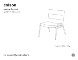
6
ITEM DESCRIPTION QUANTITY
A top panel 1
B bottom panel 1
C right end panel 1
D left end panel 1
E back panels 2
F shelves 2
G division panel 1
Bottom
(70.1 x 29cm)
Double back panel
(29 x 182.9cm)
Left side
(29 x 182.9cm)
Shelves x 4
(70.1 x 29cm)
Right side
(72.2 x 180.3cm)
Top
(75.3 x 29.2cm)
3
B
(70.1 x 28.5cm)
(28.7 x 70.2cm)
(29 x 74.9cm)
(29 x 74.9cm)
(72.2 x 72.3cm)
(147.9 x 29.2cm)
(142.7 x 29cm)
Ax1
Bx1
Ex2
Fx2
Cx1Dx1
Gx1
M
3
5
2
2
2
2
6
A
E
F
F
B
C
G
E
D

7
how to use the cam lock system
x 2
(H1) x 4
large cam
(H2) x 2
small cam
(H3) x 8
cam cover cap
(H5) x 2
short cam bolt
(H4) x 4
long cam bolt
(H6) x 2
knob
(H7) x 4
large wooden dowel
(H8) x 2
small wooden dowel
(H10) x 1
allen wrench
(H9) x 1
glue
(H11) x 4
L-bracket
(H12) x 2
hinge
(H13) x 16
1/2” pan-head screw
(H15) x 2
7/8” pan-head machine screw
(H14) x 8
Glue
(H16) x 4
2” hex-head screw
(H17) x 4 (H18) x 12
1-1/8” washer-head screw
(H20) x 1
touch-up stick
(H19) x 35
nail
(H21) x 2 sets
drawer glides
(H22) x 1
magnetic catch
(H23) x 1
strike plate
(H25) x 1
strike plate screw
(H24) x 2
magnetic catch screw
3.
1. 2. 3.
4. 5.
180°
1. 2. 3.
4.
5.
180°

8
step 1.
1. Carefully tap small wooden dowels (H3) into place.
2. Refer to page 6 for instructions on how to use the cam lock system.
(H3) x 4
wooden dowel
(H1) x 4
large cam
E
A
F
F
F
F
B
C
D

9
step 2.
1. Attach 4x metal dowels (H2) into the pre-drilled holes on side panels,
screw-In cam bolts must be screwed down ush.
(H2) x 4
metal dowel
E
A
F
F
F
F
B
B
180°
C
C
D

10
step 3.
1. Carefully tap small wooden dowels (H3) into place.
2. Refer to page 6 for instructions on how to use the cam lock system.
(H3) x 4
wooden dowel
(H1) x 2
large cam
180°
G

11
step 4.
B
1. Carefully tap small wooden dowels (H3) into place.
2. Refer to page 6 for instructions on how to use the cam lock system.
(H3) x 4
wooden dowel
(H1) x 4
large cam

12
step 5.
1. Attach 6x metal dowels (H2) into the pre-drilled holes on top panel (A),
screw-In cam bolts must be screwed down ush.
(H2) x 6
metal dowel
WHEN FITTING CAMS
ENSURE STARTING POSITION IS CORRECT
BEFORE YOU INSERT CONNECTING CAM-PILLAR
CORRECT
WRONG
A

13
step 6.
1. Attach bottom panel (B) onto side panels (C) and (D) as shown. Ensure metal dowels and wooden
dowels are aligned correctly with the holes of matching parts before attaching.
2. Secure bottom panel (B) onto side panels (C) and (D) using screwdriver to turn tting clockwise to x.
3. Refer to page 6 for instructions on how to use the cam lock system.
WHEN FITTING CAMS
ENSURE STARTING POSITION IS CORRECT
BEFORE YOU INSERT CONNECTING CAM-PILLAR
CORRECT
WRONG
180°
C
D
B

step 7.
14
1. Attach division panel (G) onto bottom panel (B) as show.
2. Secure division panel (G) using conformat screw (H13) and allen key (H10).
E
A
F
F
F
F
B
C
D
C
D
B
G
(H13) x 2
conformat screw
allen key
(H10) x 1

step 8.
15
180°
C
D
A
G
1. Attach top panel (A) onto side panels (C) (D) and division panel (G) as shown. Ensure metal dowels and wooden
dowels are aligned correctly with the holes of matching parts before attaching.
2. Secure top panel (A) onto side panels (C) (D) and division panel (G) using screwdriver to turn tting clockwise to x.
3. Refer to page 6 for instructions on how to use the cam lock system.

16
step 9.
E
E
1. Position back panels (E) as shown.

17
step 10.
1. Before attaching the back panels (E), checking the correct allocation.
Important:
The cabinet MUST
be ‘square’ when the
back is attached.
=
=
X
X
X Y = J K
K
K
Y
Y
J
J
E
E
Important:
The cabinet MUST
be ‘square’ when the
back is attached.
=
=
X
X
X Y = J K
K
K
Y
Y
J
J
E
E

18
step 11.
1. Attach back panels (E) onto back side of the unit using 40x nails (H8), with the help of the nail guide (H9),
and 3x staples (H11) with 3x screws (H12).
(H8) x 40
nail
(H11) x 3
staple
(H9) x 1
nail guide
(H12) x 3
63/64” at-head screw
E
E
E
E

step 12.
19
1. Push in by hand 4x support foot (H7) on side panels as shown.
2. Push in by hand 2x support foot (H6) on bottom panel (B) as shown.
(H7) x 4
support foot
(H6) x 2
support foot
B

20
step 13.
1. With help of an assistant carefully stand up the unit.
E
F
F
F
F
Side
/