
Complimenti per aver acquistato un prodotto: La NORDICA.
Congratulations for purchasing a product by: La NORDICA.
Wir gratulieren Sie für den Einkauf eines Einsatzes in Gusseisen: La NORDICA.
Nous vous félicitons pour l’achat d’un poêle à bois LA NORDICA!
•
Sentirsi bene e allo stesso tempo risparmiare energia con i prodotti La NORDICA diventa possibile!
Feeling well and sparing energy at the same time is a reality with the products by La NORDICA
Sich wohl zu fühlen und gleichzeitig Energie zu sparen ist nun dank den Produkten La NORDICA möglich!
Bien-être et économie d’énergie sont désormais possibles grâce aux produits LA NORDICA!
NORME DI SICUREZZA SUGLI APPARECCHI
Per il rispetto delle norme di sicurezza è obbligatorio installare
e utilizzare i nostri prodotti seguendo scrupolosamente le indicazioni fornite nel presente manuale.
SAFETY REGULATIONS ON THE APPLIANCES
To meet safety regulations, it is compulsory to install and use our products
carefully following the instructions contained in this manual.
SICHERHEITSVORSCHRIFTEN BEI DEN AUSRÜSTUNGEN
Um die Sicherheitsvorschriften zu beachten, ist es notwendig, unsere Produkte
vorsichtig nach den in diesem Handbuch enthaltenen Anweisungen zu installieren und anzuwenden.
RÉGLÉS DE SÉCURITÉ SUR LES APPAREILS
Selon les normes de sécurité sur les appareils l’acheteur
et le commerçant sont contraints de s’informer sur le fonctionnement correct sur la base des instructions d’emploi.
ISTRUZIONI PER L’INSTALLAZIONE, L’USO E LA MANUTENZIONE - IT
INSTRUCTIONS FOR INSTALLATION, USE AND MAINTENANCE - EN
ANWEISUNGEN FÜR DIE AUFSTELLUNG, DEN GEBRAUCH UND DIE WARTUNG - DE
INSTRUCTIONS POUR L’INSTALLATION, L’UTILISATION ET L’ENTRETIEN – FR
|
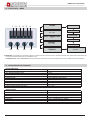
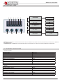
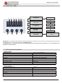
MODULO ALL INCLUSIVE
MODULO ALL INCLUSIVE 2.0
UNIVERSALE / ITALYTERMO DSA
Page is loading ...

MODULO ALL INCLUSIVE
7095520 - IT-EN-DE-FR 3
IT - INDICE
1. AVVERTENZE GENERALI ..............................................................................................................................................................7
2. DESCRIZIONE TECNICA ................................................................................................................................................................7
3. INSTALLAZIONE .............................................................................................................................................................................7
4. COLLEGAMENTO IDRAULICO .......................................................................................................................................................7
4.1. CARICO DELL’IMPIANTO ......................................................................................................................................................8
5. COLLEGAMENTO ELETTRICO ......................................................................................................................................................8
6. REGOLATORE ELETTRONICO DIGITALE PER TERMOPRODOTTI AD ACQUA .........................................................................8
6.1. TEMPERATURA ACQUA CALDA ...........................................................................................................................................8
6.2. BENESSERE ..........................................................................................................................................................................8
6.3. ANTIGELO ..............................................................................................................................................................................8
6.4. ANTIBLOCCO ........................................................................................................................................................................8
6.5. ALLARME SOVRATEMPERATURA .......................................................................................................................................9
6.6. ALLARME SONDA GUASTA .................................................................................................................................................9
6.7. SCARICO ARIA ......................................................................................................................................................................9
6.8. MENU IMPOSTAZIONI ...........................................................................................................................................................9
7. GESTIONE REGOLATORE ELETTRONICO DIGITALE “IN REMOTO” .........................................................................................9
8. MANUTENZIONE DELL’IMPIANTO IDRAULICO ............................................................................................................................9
9. FERMO ESTIVO ..............................................................................................................................................................................9
10. FLOW CHART - MENU ..................................................................................................................................................................10
11. CARATTERISTICHE TECNICHE ...................................................................................................................................................10
12. REGOLATORE ELETTRONICO / ELECTRONIC CONTROLLER / ELEKTRONISCHER REGLER / RÉGULATEUR
ÉLECTRONIQUE ...........................................................................................................................................................................23
13. SCHEMA DI INSTALLAZIONE / INSTALLATION LAY-OUT / ALLGEMEINES INSTALLATIONSSCHEMA THERMOKÜCHE /
INSTALLATION SCHEME ..............................................................................................................................................................25
EN - CONTENTS
1. GENERAL PRECAUTIONS ........................................................................................................................................................... 11
2. TECHNICAL DESCRIPTION ......................................................................................................................................................... 11
3. INSTALLATION .............................................................................................................................................................................. 11
4. WATER CONNECTION ................................................................................................................................................................. 11
4.1. SYSTEM FILLING ................................................................................................................................................................12
5. ELECTRIC CONNECTION ............................................................................................................................................................12
6. DIGITAL ELECTRONIC CONTROLLER FOR WATER HEATERS ................................................................................................12
6.1. HOT WATER TEMPERATURE .............................................................................................................................................12
6.2. COMFORT ............................................................................................................................................................................12
6.3. FROST PROTECTION .........................................................................................................................................................12
6.4. ANTI-BLOCKAGE .................................................................................................................................................................12
6.5. EXCESS TEMPERATURE ALARM ......................................................................................................................................13
6.6. FAULTY PROBE ALARM .....................................................................................................................................................13
6.7. AIR VENT .............................................................................................................................................................................13
6.8. SETTINGS MENU ................................................................................................................................................................13
7. “REMOTE” DIGITAL ELECTRONIC REGULATOR MANAGEMENT .............................................................................................13
8. WATER CIRCUIT MAINTENANCE ................................................................................................................................................13
9. SUMMER SET ASIDE ....................................................................................................................................................................13
10. FLOW CHART - MENU ..................................................................................................................................................................14
11. TECHNICALS SPECIFICATIONS ..................................................................................................................................................14
12. REGOLATORE ELETTRONICO / ELECTRONIC CONTROLLER / ELEKTRONISCHER REGLER / RÉGULATEUR
ÉLECTRONIQUE ...........................................................................................................................................................................23
13. SCHEMA DI INSTALLAZIONE / INSTALLATION LAY-OUT / ALLGEMEINES INSTALLATIONSSCHEMA THERMOKÜCHE /
INSTALLATION SCHEME ..............................................................................................................................................................25

MODULO ALL INCLUSIVE
4 7095520 - IT-EN-DE-FR
FR - TABLE DES MATIÈRES
1. AVERTISSEMENTS GENERAUX..................................................................................................................................................19
2. DESCRIPTION TECHNIQUE ........................................................................................................................................................19
3. INSTALLATION ..............................................................................................................................................................................19
4. RACCORDEMENT HYDRAULIQUE .............................................................................................................................................19
4.1. CHARGEMENT DE L’INSTALLATION .................................................................................................................................20
5. RACCORDEMENT ÉLECTRIQUE ................................................................................................................................................20
6. RÉGULATEUR ÉLECTRONIQUE DIGITAL POUR APPAREIL DE CHAUFFAGE À EAU .............................................................20
6.1. TEMPÉRATURE EAU CHAUDE ..........................................................................................................................................20
6.2. BIEN-ÊTRE ..........................................................................................................................................................................20
6.3. HORS-GEL ...........................................................................................................................................................................20
6.4. ANTIBLOCAGE ....................................................................................................................................................................20
6.5. ALARME SURCHAUFFE .....................................................................................................................................................21
6.6. ALARME SONDE EN PANNE ............................................................................................................................................21
6.7. PURGE D’AIR .......................................................................................................................................................................21
6.8. MENU PROGRAMMATIONS ...............................................................................................................................................21
7. GESTION DU REGULATEUR ELECTRONIQUE NUMERIQUE “A DISTANCE” ..........................................................................21
8. ENTRETIEN DE L’INSTALLATION HYDRAULIQUE .....................................................................................................................21
9. ARRÊT PENDANT L’ÉTÉ ..............................................................................................................................................................21
10. FLOW CHART - MENU ..................................................................................................................................................................22
11. SPÉCIFICATIONS TECHNIQUES .................................................................................................................................................22
12. REGOLATORE ELETTRONICO / ELECTRONIC CONTROLLER / ELEKTRONISCHER REGLER / RÉGULATEUR
ÉLECTRONIQUE ...........................................................................................................................................................................23
13. SCHEMA DI INSTALLAZIONE / INSTALLATION LAY-OUT / ALLGEMEINES INSTALLATIONSSCHEMA THERMOKÜCHE /
INSTALLATION SCHEME ..............................................................................................................................................................25
DE - INHALTSVERZEICHNIS
1. ALLGEMEINE HINWEISE .............................................................................................................................................................15
2. TECHNISCHE BESCHREIBUNG ..................................................................................................................................................15
3. INSTALLATIONSNORMEN ............................................................................................................................................................15
4. WASSERANSCHLUSS ..................................................................................................................................................................15
4.1. LADEN DER ANLAGE ..........................................................................................................................................................16
5. ELEKTRISCHE ANSCHLUSS .......................................................................................................................................................16
6. DIGITALE REGELELEKTRONIK FÜR WASSERGEFÜHRTE HEIZGERÄTE ..............................................................................16
6.1. WARMWASSERTEMPERATUR ...........................................................................................................................................16
6.2. WOHLBEFINDEN .................................................................................................................................................................16
6.3. FROSTSCHUTZ ...................................................................................................................................................................16
6.4. ANTIBLOCKIERFUNKTION .................................................................................................................................................17
6.5. ALARM ÜBERHITZUNG ......................................................................................................................................................17
6.6. ALARM TEMPERATURFÜHLER DEFEKT .........................................................................................................................17
6.7. ENTLÜFTUNG ......................................................................................................................................................................17
6.8. MENÜ EINSTELLUNGEN ....................................................................................................................................................17
7. „FERNSTEUERUNG” DER DIGITALEN REGELELEKTRONIK ....................................................................................................17
8. WARTUNG DER WASSERANLAGE ............................................................................................................................................17
9. SOMMERLICHE STILLLEGUNG ..................................................................................................................................................18
10. FLOW CHART - MENU ..................................................................................................................................................................18
11. TECHNISCHE DATEN ...................................................................................................................................................................18
12. REGOLATORE ELETTRONICO / ELECTRONIC CONTROLLER / ELEKTRONISCHER REGLER / RÉGULATEUR
ÉLECTRONIQUE ...........................................................................................................................................................................23
13. SCHEMA DI INSTALLAZIONE / INSTALLATION LAY-OUT / ALLGEMEINES INSTALLATIONSSCHEMA THERMOKÜCHE /
INSTALLATION SCHEME ..............................................................................................................................................................25

MODULO ALL INCLUSIVE
7095520 - IT-EN-DE-FR 5
DICHIARAZIONE DI CONFORMITA’ DEL COSTRUTTORE
Oggetto: Assenza di amianto e cadmio
Si dichiara che tutti i nostri apparecchi vengono assemblati con materiali che non presentano parti di amianto o suoi derivati e che nel
materiale d’apporto utilizzato per le saldature non è presente/utilizzato in nessuna forma il cadmio, come previsto dalla norma di riferimento.
Oggetto: Regolamento CE n. 1935/2004
Si dichiara che in tutti gli apparecchi da noi prodotti, i materiali destinati a venire a contatto con i cibi sono adatti all’uso alimentari, in
conformità al Regolamento CE in oggetto.
DECLARATION OF CONFORMITY OF THE MANUFACTURER
Object: Absence of asbestos and cadmium
We declare that the materials used for the assembly of all our appliances are without asbestos parts or asbestos derivates and that in the
material used for welding, cadmium is not present, as prescribed in relevant norm.
Object: CE n. 1935/2004 regulation.
We declare that in all products we produce, the materials which will get in touch with food are suitable for alimentary use, according to the
a.m. CE regulation.
KONFORMITÄTSERKLÄRUNG DES HERSTELLERS
Betreff: Fehlen von Asbest und Kadmium
Wir bestätigen, dass die verwendeten Materialen oder Teilen für die Herstellung der La Nordica Geräte ohne Asbest und Derivat sind und
auch das Lot für das Schweißen immer ohne Kadmium ist.
Betreff: Ordnung CE n. 1935/2004.
Wir erklären in alleiniger Verantwortung, dass die Materialen der Teile, die für den Kontakt mit Lebensmitteln vorgesehen sind, für die
Nahrungsbenutzung geeignet sind und der Richtlinien CE n. 1935/2004 erfüllen.
DÉCLARATION DE CONFORMITÉ DU CONSTRUCTEUR
Objet: Absence d’amiante et de cadmium
Nous déclarons que tous nos appareils sont assemblés avec des matériaux ne comportant pas de parties en amiante ou ses dérivés et
que dans le matériau d’apport utilisé pour les soudures le cadmium n’est pas présent ni utilisé sous aucune forme que ce soit, comme il
est prévu par la norme de référence.
Objet: Règlement CE n. 1935/2004
Nous déclarons que tous nos produits, les matériaux destinés à entrer en contact avec les aliments sont indiqués pour l’usage des
aliments, conformément au Règlement CE cité à l’objet.

MODULO ALL INCLUSIVE
6 7095520 - IT-EN-DE-FR
INFORMAZIONI AL UTENTE SULLO SMALTIMENTO DELLE APPARECCHIATURE DA PARTE DEI PRIVATI
NEL TERRITORIO DELL’UNIONE EUROPEA
Ai sensi dell’art.13 del decreto legislativo 25 luglio 2005, n.151 «attuazione delle direttive 2002/95/CE e 2003/1 08/CE, relative
sostanze alla riduzione dell’uso di sostanze pericolose nelle apparecchiature elettriche ed elettroniche, nonché allo smaltimento dei
riuti». il simbolo del cassonetto barrato riportato sull’apparecchiatura o sulla confezione indica che il prodotto alla ne della propria
vita utile deve essere raccolto separatamente dagli altri riuti. l’utente dovrà, pertanto, conferire l’apparecchiatura giunta a ne vita agli
idonei centri di raccolta differenziata dei riuti elettronici ed elettrotecnici, oppure riconsegnarla al rivenditore al momento dell’acquisto
di una nuova apparecchiatura di tipo equivalente, in ragione di uno a uno. L’adeguata raccolta differenziata per l’awio successivo
dell’apparecchiatura e dismessa al riciclaggio, al trattamento e allo smaltimento ambientalmente compatibile, contribuisce ad evitare
possibili effetti negativi sull’ambiente e sulla salute e favorisca il reimpiego e/o riciclo dei materiali di cui è composta l’apparecchiatura.
Lo smaltimento abusivo del prodotto da parte dell’utente comporta l’applicazione delle sanzioni amministrative previste dalla normativa
vigente, di cui al digs n. 22/1997 (articolo 50 e seguenti del digs n. 22/1997).
El símbolo del contenedor tachado, aplicado en el embalaje o en el producto, indica que éste no debe desecharse junto a los residuos domésticos
sino depositarse en un punto de recogido esp.ecíco para aparatos eléctricos y electrónicos. El reciclaje y. la eliminación ecocompatible del producto
contribuyen a proteger el medio ambiente y la salud de la población. Pora más información sobre el reciclaje de este producto, consulte con el Ayuntamiento
de su ciudad, con el servicio local de eliminación de residuos o con el comercIo donde te, ha adquirido.
O símbolo em questão, quando aplicado no produto ou embalagem, indica que o produto não deve ser considerado lixo doméstico normal e deve ser
levado a um centro de recolha para reciclagem de equipamentos eléctricos. Eliminando este produto nas devidas condições estar·se·á a contribuir para
evitar as potenciais conseqüências negativas decorrentes de uma eliminação inadequada do mesmo. Para mais informações sobre a reciclagem do
produto, contacte o serviço especializado da Câmara municipal, o serviço local de eliminação de desperdícios ou o comerciante onde o adquiriu.
This symbol appearing on a product or its packaging indicates that the product must not be considered os normal household waste, but must be token to a
special waste collection centre for recycling electric and electronic appliances. Disposing of this product appropriately helps ovoid any potentially negative
consequences which could arise from its incorrect disposal. For more detailed information on recyding of this product, contact your local council, the local
waste disposal service or the shop where you bought the product..
Das auf dem Produkt oder derVerpackung angebrachte Symbol besagt, dass das Produkt nicht als normaler Hausmull anzusehen ist, sondern bei
speziellen Sammelstellen für das Recycling von Elelktro- und Elektronik-Altgeraten abzugeben ist. Durch die ordnungsgemäße Entsorgung dieses
Produktes werden mögliche negative Folgen vermieden, die aus einer unsachgemäßen Entsorgung. des Produktes entstehen konnten. Ausführlichere
Informationen zum Recycling, dieses Produktes liefern das Gemeindeamt, der örtliche Müllentsorgungsdienst oder der Händler, bei dem das Produkt
gekauft wurde
Le symbole en question appliqué sur le produit ou sur l’emballage indique que le produit ne doit pas être considéré comme un déchet domestique normal,
mais doit être déposé dans un point de collecte différenciée approprié au recyclage d’appareils électriques et électroniques.
Le respect de cette norme permet d’éviter toute conséquence négative qui pourrait dériver d’une élimination du produit de manière non adéquate. Pour
des informations plus détaillées sur le recyclage de ce produit, contacter le service de la mairie compétent, le service local d‘élimination des déchets ou
le magasin auprès duquel le produit a été acheté.
Page is loading ...
Page is loading ...
Page is loading ...
Page is loading ...

MODULO ALL INCLUSIVE
7095520 - IT-EN-DE-FR 11
1. GENERAL PRECAUTIONS
La NORDICA S.p.A. responsibility is limited to the supply of the appliance. The installation must be carried out scrupulously according to the
instructions provided in this manual and the rules of the profession. Installation must only be carried out by a qualied technician who works
on behalf of companies suitable to assume the entire responsibility of the system as a whole.
This appliance is not suitable for the use of inexperienced people (included children) or with physical, sensorial and mental reduced
capacities. They have to be controlled and educated in the use of the appliance from a responsible person for their security. The children
have to be controlled to be sure that they would not play with the appliance. (EN60335-2-102/7.12).
La NORDICA S.p.A. declines any responsibility for the product that has been modied without written authorisation as well as for
the use of non-original spare parts.
DO NOT MODIFY THE APPLIANCE.
NORDICA S.p.A. cannot be held responsible for lack of respect for such precautions.
2. TECHNICAL DESCRIPTION
Hydraulic module for La NORDICA thermoproducts: - All Inclusive UNIVERSAL module; - ITALYTERMO D.S.A. All Inclusive module.
The module is equipped with:
• safety devices,
• a closed expansion vessel,
• pumps,
• domestic hot water production system.
Management and operation are controlled by a digital electronic regulator which always installed on-board the machine, and a separately-
installed second display screen connected to the main and unstable one is available ONLY for the UNIVERSAL module
3. INSTALLATION
Installation of the product and auxiliary equipment in relation to the heating system must comply with all current Standards and Regulations
and to those envisioned by the law.
Installation relating to the connections of the system, commissioning and the check of the correct functioning must be carried out in
compliance with the regulations in force by authorised professional personnel with the requisites required by the law, being national,
regional, provincial or town council present in the country within which the appliance is installed, besides these present instructions.
Installation must be carried out by authorised personnel who must provide the buyer with a system declaration of conformity certicate and
will assume full responsibility for nal installation and as a consequence the correct functioning of the installed product.
All operations must be performed with mains power disconnected.
WARNING : installation, connections and testing must be performed by qualied personnel acting in compliance with the standards in
force and as described in the heating appliance instruction booklet Correct operation of the appliance is only guaranteed for pumps and
valves approved by La Nordica. La Nordica is not liable for any improper use of the appliance.
NB. All piping must be insulated in accordance with applicable standards (in Italy law 10/91).
IMPORTANT: temperature safety sensors must be in place on the machine or at a distance no greater than 30 cm from the ow connection
of the thermo-product. Whenever the thermo products lack a device, those missing can be installed on the thermo product ow pipe,
within a distance no greater than 1m from the thermo product.
NOTE: the standard UNIVERSAL module is equipped with a 3-bar SRV valve and a 95°C TRV with double thermal safety to be installed in
the hydraulic system in compliance with all current Standards and Regulations and pursuant to the Law.
Before installation, accurately wash the pipes of the system in order to remove any residuals that could compromise the correct functioning
of the appliance.
IMPORTANT:
a) In case of water leaking, close the water supply and promptly warn the after sales technical service;
b) The system working pressure must periodically be checked.
c) If not using the boiler for a long period of time, it is recommended that the after sales technical service is contacted to carry out at
least the following operations:
• close the water taps of both the thermal system and the domestic hot water system;
• empty the thermal system and the domestic hot water system if there is risk of freezing.
4. WATER CONNECTION
IMPORTANT: after having transported / handled the All Inclusive Module, check tightness of all the compression nuts on the copper pipes.
Take special care when connecting the Module to the plumbing system to avoid bending the copper pipes in the KIT. To counter the
tightening force exerted on the plumbing system connection pipe, use a wrench or other tool on the terminal in the KIT being connected.
WARNING: after having connected the Module to the plumbing system, check tightness of all the compression nuts on the copper pipes.
The two All Inclusive Modules are already equipped with a VSP valve (Thermal Relief Valve) and a SRV valve (Safety Relief Valves), as
well as being pre-arranged to be installed in open vessel system.
The VST valve (Thermal Relief Valve) is supplied disassembled with the UNIVERSAL Module, while it is already installed in the All Inclusive
Module for ITALYTERMO DSA.
IMPORTANT: for open vessel or closed vessel installation refer to the instructions manual of the thermoproduct combined with the All
Inclusive Module.

MODULO ALL INCLUSIVE
12 7095520 - IT-EN-DE-FR
4.1. SYSTEM FILLING
Some examples, purely indicative of the installation, are reported at chapter 1, while the connections to the thermoproduct are reported at
chapter 13.
WARNING: The Modulo All Inclusive system has to be lled only by means of the tap (pos. 3). When the manometer (M) shows a
pressure of 1-1,2 bar, close the tap.
During this phase, open all the bleed valves of the All Inclusive Module (SF) and the radiators to prevent the formation of air sacks,
checking the outlet of water to avoid unpleasant oodings.
The installation watertight test has to be performed with the normal cold operating pressure (please refer to the instruction manual of the
thermoproduct matched with the Modulo All Inclusive).
The installation must always be full of water even when the thermo-replace is not used. During winter season the non use has
to be faced by adding antifreeze substances.
5. ELECTRIC CONNECTION
The control unit and the plant must be installed and connected by authorized personnel according to the standards in force.
Connect the feeding cable of the switchboard with an electronic bipolar switch respecting at least a 3 mm distance between the contacts
(power supply 230V~ 50 / 60Hz, it is necessary to provide for the correct connection to the grounding plant).
WARNING: The COMMAND must be connected to the mains with a differential line cut-off switch according to the regulations in force.
Correct operation of the appliance is only guaranteed for pumps and valves approved by La Nordica. La Nordica is not liable for any
improper use of the appliance.
WARNING: In any case, the power cable has to be replaced by authorised personnel ONLY (entitled by La Nordica):
authorised dealers and/or tter.
6. DIGITAL ELECTRONIC CONTROLLER FOR WATER HEATERS
This digital electronic device controls the activation of two circulating pumps and manages the 3-way valve in the All Inclusive Module.
The digital controller, as well as controlling the water temperature, also manages any blockage of the pumps in the All Inclusive Module.
The COMFORT function obtains a considerable increase in the system water temperature compared to the NORMAL function.
The internal menu can be used to:
• set the language used to show information on the display (IT-EN-DE-FR);
• set the temperature in °C o °F;
• enable or disable the alarm buzzer (Buzzer);
• change display brightness;
• access the technical menu.
WARNING: the parameters in the technical menu should never be modied. Such operation must only be performed by an authorised
La NORDICA S.p.A. service centre.
La NORDICA S.p.A. is not liable for product malfunctions due to the parameters in the technical menu being modied without
authorisation.
6.1. HOT WATER TEMPERATURE
The water temperature is shown on the display by pressing and holding button T2 (see chapter 10).
NOTE: The circulating pump activation temperature is a factory setting.
In the event of excess water temperature the device warns the user with an indicator light and an audible signal; the latter may be enabled
or disabled via the BUZZER function in the MENU.
See EXCESS TEMPERATURE ALARM.
6.2. COMFORT
Pressing and holding button T3 activates the COMFORT function.
When the COMFORT function is active, LED 2 ashes and the function remains active for 15 minutes; if the maximum water temperature
is reached in this time, the LED remains on steady.
After 15 minutes digital controller automatically returns to the NORMAL function (LED 2 off).
NOTE: disable the COMFORT function by pressing and holding button T3
6.3. FROST PROTECTION
The frost protection function is always active on the device and acts by starting the pump when the temperature measured by the probe is
less than 5°C / 41°F (xed threshold).
When the frost protection function is active, LED 1 Danger comes on and the message “FROST PROTECTION” is shown on the display.
6.4. ANTI-BLOCKAGE
The ANTI-BLOCKAGE function automatically starts the pumps connected to the controller for 30 seconds after an extended period of
inactivity (~96 hours without power being disconnected).
When the ANTI-BLOCKAGE function is activated, the display shows the message “ANTI-BLOCKAGE”.
WARNING: to ensure the ANTI-BLOCKAGE function is not disabled, always leave the digital controller connected to the power supply
(the display shows OFF).

MODULO ALL INCLUSIVE
7095520 - IT-EN-DE-FR 13
6.5. EXCESS TEMPERATURE ALARM
When the temperature measured by the water probe exceeds 87°C / 188.6°F (xed threshold set), this alarm is activated, starting the
circulating pumps.
When the alarm is activated, LED 1 Danger comes on and the message “EXCESS TEMPERATURE” is shown on the display.
6.6. FAULTY PROBE ALARM
When a probe fault occurs, this alarm is activated, starting the circulating pumps.
When the alarm is activated, LED 1 Danger comes on and the message “FAULTY PROBE” is shown on the display.
6.7. AIR VENT
Air inside the water circuit causes noise and may damage the circulating pumps. The presence of air may occur following installation of the
All Inclusive Module or any other work on the water circuit.
Vent any air inside the system by operating the digital controller as follows:
• the water in the system must be at room temperature;
• with the digital controller ON, press buttons T2 and T3 together. The display shows the message “AIR VENT”.
6.8. SETTINGS MENU
See Chapter 13.
Pressing and holding the MENU button (T4) accesses the LANGUAGE menu. (Press T1 to exit the menu).
Press the MENU button again briey to modify the language displayed (IT; EN; DE; FR) using the T2-T3 buttons. Press MENU to conrm
the selection.
Press the T2 button to access the BUZZER menu (enable the audible signal). Press the MENU button to enable or disable the buzzer using
the T2-T3 buttons (ON / Off). Press MENU to conrm the selection.
Press the T2 button to access the SET DEGREES menu (display the temperature in °C / °F). Press the MENU button to modify, using the
T2-T3 buttons, the temperature display from °C to °F and vice-versa. Press MENU to conrm the selection.
Press the T2 button to access the DISPLAY menu (brightness from 0 to 100). Press the MENU button to set the required display brightness,
using the T2-T3 buttons, from 0 to 100. Press MENU to conrm the selection.
Press the T2 button to access the TECHNICAL SETTINGS menu.
WARNING: the parameters in the technical menu should never be modied. Such operation must only be performed by an Authorised
La NORDICA S.p.A. Service Centre. La NORDICA S.p.A. is not liable for product malfunctions due to the parameters in the
technical menu being modied without authorisation.
7. “REMOTE” DIGITAL ELECTRONIC REGULATOR MANAGEMENT
This application is useful when the All Inclusive UNIVERSAL module is not installed near the thermoproduct it is associated with.
The digital regulator installed in the All Inclusive UNIVERSAL module is managed by the remote regulato (ONLY included in ther standard
supply of the UNIVERSAL module) which has identical functions.
When the two digital regulators are connected to each other, the lighting of both screens will be less bright. This phenomenon is completely
normal and has been designed specically to stop the screens from overheating.
IMPORTANT: the ambient temperature is displayed on the remote screen followed by the letter “A”, while the temperature of the water in
the boiler is followed by the letter “R”. The thermoproduct boiler water temperature probe (l1) must be connected directly to the remote
digital regulator. The probe cable can have a maximum length of 5 metres.
IMPORTANT: the digital regulator installed in the All Inclusive UNIVERSAL module must be connected to the remote digital regulator, as
shown in Picture 2 at page 24, through a bipolar electric cable (NOT included), with a length that does exceed 100 metres
8. WATER CIRCUIT MAINTENANCE
With the system switched off, once a year carry out the following checks:
• Check the operation and efciency of the blowdown and safety valves. If they are defective, contact your authorised installer. IT IS
STRICTLY FORBIDDEN TO REMOVE OR TAMPER WITH THE SAFETY DEVICES.
• Make sure that the system has been lled and is pressurised (see the manual for the heating appliance combined with the All
Inclusive Module).
9. SUMMER SET ASIDE
ATTENTION: the installation must be kept constantly full of water even in periods in which the use of thermoreplaces is not required.
During winter time, inactivity must be faced by adding antifreeze substances.
OPEN expansion VESSEL system: check the water level in the expansion tank and remove any air from the system by bleeding the
radiators; also check to make sure that the plumbing and electrical accessories (control unit, circulator) are working properly..

MODULO ALL INCLUSIVE
14 7095520 - IT-EN-DE-FR
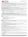
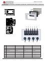
1 2 3 4 5 6
T4 T3 T2
T1
LANGUAGE
BUZZER
ON - OFF
DISPLAY
10 - 100%
TECHNICAL
SETTINGS
SETTINGS FACTORY
CODE ---
SET DEGREES
°C- F
ITALIANO
ENGLISH
FRANCAIS
ESPANOL
DEUTSH
WARNING: the parameters in the technical menu should never be modied. Such operation must only be performed by an Authorised La NORDICA
S.p.A. Service Centre.
La NORDICA S.p.A. is not liable for product malfunctions due to the parameters in the technical menu being modied without authorisation.
10. FLOW CHART - MENU
11. TECHNICALS SPECIFICATIONS
SPECIFICATIONS
POWER SUPPLY 230 V~ +15-10% 50/60 Hz
POWER INPUT Max 2VA
MAX PROBE TEMPERATURE 120°C
OPERATING TEMPERATURE 0 – 60°C
OVERALL DIMENSIONS 120x74x51 (3 gang switch box)
CONTAINER RAL9001 faceplate, BLACK frame
INDEX OF PROTECTION IP40
PUMP CONTROLLED Max 400 W
VALVE CONTROLLED Max 400 W
PUMP CONTROL RANGE 10 – 78°C (C1 default 75°C - C2 default 65°C)
VALVE CONTROL RANGE 10 – 78°C
SIGNALS
PUMP ON Led 4 - 5
3-WAYS VALVE ACTIVE Led 6
OUTLET TEMPERATURE Ramp 0 - 100°C resolution 1°C
EXCESS WATER TEMPERATURE ALARM / PROBE DAMAGED Led 1 with audible signal (selectable)
ANTI-BLOCK Led 1
FROST PROTECTION Led 1
DOMESTIC HOT WATER Led 3
COMFORT function Led 2
Page is loading ...
Page is loading ...
Page is loading ...
Page is loading ...
Page is loading ...
Page is loading ...
Page is loading ...

MODULO ALL INCLUSIVE
22 7095520 - IT-EN-DE-FR
1 2 3 4 5 6
T4 T3 T2
T1
LANGUAGE
BUZZER
ON - OFF
DISPLAY
10 - 100%
SET
TECNIQUE
REGLAGE USINE
CODE ---
SET DEGRÉS
°C- F
ITALIANO
ENGLISH
FRANCAIS
ESPANOL
DEUTSH
10. FLOW CHART - MENU
ATTENTION: il est absolument déconseillé de modier les paramètres à l’intérieur du menu technique. Cette opération doit exclusivement
être effectuée par un centre d’assistance agréé La NORDICA S.p.A.
La NORDICA S.p.A. ne peut être tenu pour responsable du mauvais fonctionnement de l’appareil en cas de modication des
paramètres sans autorisation.
11. SPÉCIFICATIONS TECHNIQUES
SPÉCIFICATIONS
ALIMENTATION 230 V~ +15-10% 50/60 Hz
PUISSANCE ABSORBÉE
Max 2VA
TEMPÉRATURE SONDE MAXI
120°C
TEMPÉRATURE DE SERVICE
0 – 60°C
DIMENSIONS
120 x 74 x 51 (boîte 3 modules)
COFFRET
Platine RAL 9001 châssis NOIR
DEGRÉ DE PROTECTION
IP40
COMMANDE CIRCULATEUR
Max 400 W
COMMANDE VANNE
Max 400 W
PLAGE DE RÉGLAGE CIRCULATEUR
10 – 78°C (C1 default 75°C - C2 default 65°C)
PLAGE DE RÉGLAGE VANNE
10 – 78°C
SIGNALISATIONS
CIRCULATEUR EN MARCHE
Led 4 - 5
VANNE 3 VOIES ACTIVÉE
Led 6
TEMPÉRATURE DE DÉPART
Rampe 0 - 100°C précision 1°C
ALARME SURCHAUFFE TEMPÉRATURE EAU / Sonde eau est en panne
Led 1 avec signal sonore (sélectionnable)
ANTIBLOCAGE
Led 1
ANTIGEL
Led 1
EAU SANITAIRE
Led 3
fonction BIEN-ÊTRE Led 2

MODULO ALL INCLUSIVE
23 7095520 - IT-EN-DE-FR
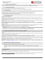
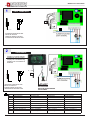
1 2 3 4 5 6
T4 T3 T2 T1
1
ALLARME ALARM ALARM ALARME
2
BENESSERE CONFORT WOHLBEFINDEN BIEN-ÊTRE
3
Acqua sanitaria Domestic hot water Warmwasserspeicher Eau sanitaire
4
Circolatore 1 Circulator 1 Pumpe 1 Circulateur 1
5
Circolatore 2 Circulator 2 Pumpe 2 Circulateur 2
6
Valvola 3 vie Valvola 3 vie 3-wege-ventil aktiv Vanne 3 voies
T1
ON / OFF ON / OFF ON / OFF ON / OFF
T2
Temperatura acqua Operating temperature Betriebstemperatur Température de l’eau
T3
BENESSERE CONFORT WOHLBEFINDEN BIEN-ÊTRE
T4
MENU MENU MENU MENU
125
80
45
12. REGOLATORE ELETTRONICO / ELECTRONIC CONTROLLER / ELEKTRONISCHER REGLER / RÉGULATEUR
ÉLECTRONIQUE

MODULO ALL INCLUSIVE
24 7095520 - IT-EN-DE-FR
I1
1
Display a controllo remoto
Display for remote control
Display für Fernbedienung
Display pour commande à
distance
I1
2
20mm
20mm
INTERRUTTORE BIPOLARE
BIPOLAR SWITCH
ZWEIPOLIGER SCHALTER
INTERRUPTEUR BIPOLAIRE
INTERRUTTORE BIPOLARE
BIPOLAR SWITCH
ZWEIPOLIGER SCHALTER
INTERRUPTEUR BIPOLAIRE
GND
Giallo / Verde Yellow / Green Gelb /Grün Jaune-vert
I1
Sonda regolatore Regulator Probe Einstellsonde Sonde régulateur
I2
Sonda Puffer
Puffer Probe Puffersonde Sonde Puffer
I3
Sonda Puffer
Puffer Probe Puffersonde Sonde Puffer
I4
Flussostato Flow switch Flussmesser Fluxostat
N
Blu - Alimentazione Blue - Power supply Blau - Stromversorgung Bleu - Alimentation
Ph
Marrone - Alimentazione Brown - Power supply Braun - Stromversorgung Marron - Alimentation
V1
Marrone - Circolatore 1 Brown - Circulator 1 Braun - Pumpe 1 Marron - Circulateur 1
V2
Marrone - Circolatore 2 Brown - Circulator 2 Braun - Pumpe 2 Marron - Circulateur 2
V3
Marrone - Valvola 3 vie Brown - 3-ways valve active Braun - 3-wege-ventil aktiv Marron - Vanne 3 voies
ITALY TERMO DSA
UNIVERSALE
L max = 100 m
L = 5 m
NON FORNITO
NOT SUPPLIED
NICHT IM LIEFERUMFANG
PAS FOURNIS

MODULO ALL INCLUSIVE
25 7095520 - IT-EN-DE-FR
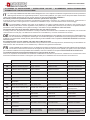
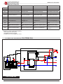
13. SCHEMA DI INSTALLAZIONE / INSTALLATION LAY-OUT / ALLGEMEINES INSTALLATIONSSCHEMA
THERMOKÜCHE / INSTALLATION SCHEME
IT
La nostra responsabilità è limitata alla fornitura dell’apparecchio. Il suo impianto va realizzato a regola d’arte secondo le prescrizioni
delle seguenti istruzioni e le regole della professione, da personale qualicato, che agisce a nome di imprese adatte ad assumere
l’intera responsabilità dell’impianto secondo quanto riportato al capitolo
AVVERTENZE GENERALI.
Gli schemi presenti sono puramente indicativi non hanno quindi valore di progetto.
A termini di legge la presente documentazione è strettamente condenziale e riservata e ne è vietata la riproduzione, l’utilizzazione e la
comunicazione a terzi. La divulgazione non consentita da La NORDICA S.p.A. verrà sanzionata secondo i termini di legge.
EN
Our responsibility is limited to the supply of the appliance. Its system is realised precisely according to the provisions of the
following instructions and the regulations of the profession, by qualied staff, which acts in the name of companies suitable to
assume the entire responsibility of the system according to that stated in chapter
GENERAL PRECAUTIONS.
The present planes are purely indicative, therefore they have not value as project.
According to the laws, the present documentation is closely condential and reserved and it is forbidden the reproduction, the use and the
communication to a third party. The diffusion not allowed from La NORDICA S.p.A. will be sanctioned from the laws.
DE
Die Haftung der Fa. La NORDICA beschränkt sich auf die Gerätelieferung. Die Installation muss fachgerecht in Übereinstimmung
mit den Vorschriften der folgenden Anweisungen und den Berufsregeln von qualiziertem Personal vorgenommen werden, das
im Namen von Unternehmen handelt, die die gesamte Haftung für die Installation wie in Kapitel
ALLGEMEINE HINWEISE beschrieben
übernehmen kann.
Die gezeigten Pläne sind rein indikativ, und haben keinen Wert als Projekt.
Im Einklang mit dem Gesetz ist diese Dokumentation streng vertraulich und ist die Reproduzieren, die Benutzung und die Diffusion an
Dritte verboten. Die nicht erlaubte von La NORDICA S.p.A. Diffusion wird gesetzlich sanktioniert.
FR
La responsabilité de La NORDICA S.p.A. est limitée à la fourniture de l’appareil. L’installation doit être réalisée selon les règles de
l’art et selon les instructions du manuel et des règles de la profession, par personnes qualiés, qui agissent à nom des sociétés
qui s’endossent entièrement la responsabilité de l’installation, selon les indications du chapitre
AVERTISSEMENTS GENERAUX.
Les schémas présentés sont purement indicatives et n’ont pas valeur de projet.
Selon la loi, la présente documentation est strictement condentielle et réservée. La reproduction, l’utilisation et la communication à tiers
de telle documentation est interdite. La divulgation pas autorisée par La NORDICA sera sanctionnée selon les termes de loi.
IT - LEGENDA EN - KEY DE - ZEICHENERKLÄRUNG FR - CLÉ
C1-C2 Circolatore Circulator Pumpe Circulateur
CM Collettore Mandata impianto Supply collector Kollektor Zulauf Collecteur refoulement
CR Collettore Ritorno impianto Return collector Kollektor Rucklauf Collecteur défoulement
M Manometro Manometer Manometer Manomètre
SF Sato Vent Ablass Mise a l’air libre
SP Scambiatore piastre Plate exchanger Austauscher mit Platten Échangeur plaques
VDM
Valvola deviatrice
motorizzata
Motorized deviator valve Motorisiertes Ablenkventil Vanne déviatrice motorisée
VSP Valvola di sicurezza 3 bar 3 bar Safety valve Sicherheitsventil 3 bar Vanne de sécurité 3bar
VST Valvola scarico termico 95°C Thermal drain valve 95°C Wärmeableitventil 95°C
Vanne de décharge
thermique 95°C
I1 Sonda regolatore Regulator Probe Einstellsonde Sonde régulateur
I2 Sonda Puffer Puffer Probe Puffersonde Sonde Puffer
I3 Sonda Puffer Puffer Probe Puffersonde Sonde Puffer
I4
Flussostato (9) Flow switch Flussmesser Fluxostat
1
MANDATA caldaia
termocucina
DELIVERY central heating ZUFUHR Kessel AMENÉE chaudière
2
RITORNO caldaia
termocucina
RETURN central heating RUCKLAUF Kessel RETOUR chaudière
3
Rubinetto a cacciavite, carico
Modulo All Inclusive
Drain cock Loading
Modulo All Inclusive
Kugelhahn mit Schlauchtülle
Ladung Modulo All Inclusive
Robinet à boisseau
sphérique Chargement du
Modulo All Inclusive

MODULO ALL INCLUSIVE
26 7095520 - IT-EN-DE-FR
VSP
VST
95°C
TS
VDM
C1
C2
SP
8
6
CM
CR
1
2
6
13
4
I3
I2
5
I1
I4
FL
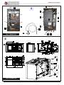
IT - LEGENDA EN - KEY DE - ZEICHENERKLÄRUNG FR - CLÉ
4
Sonda valvola VST Probe VST valve Fühler Ventil VST Sonde vanne VST
5
MANDATA Acqua sanitaria Sanitary water Sanitärwasser Eau sanitaire
6
Alimentazione acqua fredda Cold water feed Kaltwasserversorgung Alimentation D‘eau froide
7
Scarico impianto Heating system outlet Anlageabuss Décharge d’installation
8
Regolatore elettronico Electronic controller Elektronischer regler Régulateur électronique
9 Flussostato Flow switch Flussmesser Fluxostat
*10
Tubo di sicurezza da Ø 1” Safety pipe ø 1” Sicherheitsrohr ø 1” Tuyau de sécurité ø 1”
*11
Tubo di carico ø ¾” Load pipe ø ¾” Zufuhrrohr ø ¾” Tuyau de remplissage ø ¾”
12
ENTRATA Sistema integrato
DSA
INLET Integration System
DSA
EINGANG Integriert System
DSA
ENTRÉE System intégré
DSA
13
USCITA Sistema integrato
DSA
OULET Integration System
DSA
AUSGANG Integriert System
DSA
SORTIE System intégré
DSA
14 Display a controllo remoto Display for remote control Display für Fernbedienung
Display pour commande à
distance
* Sistema con Vaso di espansione APERTO
OPEN expansion Tank system
OFFENEM Ausdehnungsgefäß
Installation avec vase d’expansion ouvert,
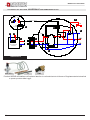
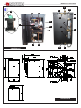
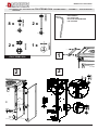
13.1. MODULO ALL INCLUSIVE PER ITALYTERMO DSA
ITALY TERMO DSA


MODULO ALL INCLUSIVE
28 7095520 - IT-EN-DE-FR
VST
95°C
VSP
CM
CR
TS
Termoprodotto DSA
La NORDICA
I4
FL
C2
I3
I2
C1
I1
L= 5 m
VDM
SP
DSA
VSP
L max = 100 m
3
8
5
6
13
14
4
12
1 1
2 2
VST 95°C
VSP
I1
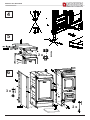
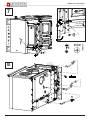
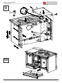
13.2. MODULO ALL INCLUSIVE UNIVERSALE PER TERMOPRODOTTI DSA
UNIVERSALE
Fornite di SERIE da installare nell’impianto idraulico in conformità a tutte le Norme e Regolamentazioni attuali ed
a quanto previsto dalla Legge.


Page is loading ...
Page is loading ...
Page is loading ...
Page is loading ...
-
 1
1
-
 2
2
-
 3
3
-
 4
4
-
 5
5
-
 6
6
-
 7
7
-
 8
8
-
 9
9
-
 10
10
-
 11
11
-
 12
12
-
 13
13
-
 14
14
-
 15
15
-
 16
16
-
 17
17
-
 18
18
-
 19
19
-
 20
20
-
 21
21
-
 22
22
-
 23
23
-
 24
24
-
 25
25
-
 26
26
-
 27
27
-
 28
28
-
 29
29
-
 30
30
-
 31
31
-
 32
32
-
 33
33
-
 34
34
-
 35
35
-
 36
36


La Nordica Modulo All Inclusive Italy Termo D.S.A. 2.0 Owner's manual
- Type
- Owner's manual
- This manual is also suitable for
Ask a question and I''ll find the answer in the document
Finding information in a document is now easier with AI
in other languages
Related papers
-
La Nordica Controller for thermoproducts Owner's manual
-
-
-
-
-
-
-
-
-
Other documents
-
La Nordica-Extraflame TermoRosa XXL D.S.A. User manual
-
Nordica TermoSovrana DSA Instructions For Installation, Use And Maintenance Manual
-
Ferroli PEGASUS D 30 K 100 LN Instructions For Use, Installation And Maintenance
-
 Unical KONe User manual
-
 Unical KUTter B inox User manual
-
Baxi Power HT 1.1000 Installation, Operation and Maintenance Manual
-
-
 Unical !DEA User manual
-
 Unical KON B 28 User manual
-
 Unical KUTter B inox Installation guide


