Page is loading ...

Specifications
Wingspan: 33 in (846mm)
Length: 35.4 in (381mm)
Wing Area: 206 sq in (13.2 sq dm)
Weight w/o Battery: 34–36 oz (964–1021 g)
Weight w/Battery: 43–46 oz (1219–1304 g)
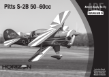
BAe Hawk 15 DF
Assembly Manual
Pilots not included (PKZ4414)

2 E-flite BAe Hawk ARF Assembly Manual
Using the Manual
This manual is divided into sections to help make
assembly easier to understand, and to provide breaks
between each major section. In addition, check boxes
have been placed next to each step to keep track
of its completion. Steps with a single circle () are
performed once, while steps with two circles ( )
indicate that the step will require repeating, such as for
a right or left wing panel, two servos, etc.
Remember to take your time and follow the directions.
Contents of Kit/Parts Layout
Replacement Parts
EFL8026 Fuselage with side hatch
EFL8027 Canopy Hatch
EFL8028 Wing Panel
with Hinged Aileron Left
EFL8029 Wing Panel
with Hinged Aileron Right
EFL8030 Horizontal Stabilizer
with Elevator L & R
EFL8031 Pushrods and Carbon
Wing Tubes
EFL8032 Plastic Accessories
EFL8033 Landing Gear and Wheels
with Hardware
EFL8034 Control Hardware
Introduction
Designed as a trainer and light combat aircraft for use
by the British Royal Air Force, the British Aerospace
(BAe) Hawk was mainly used to teach air combat,
air-to-air firing, air-to-ground firing, low-altitude
flying techniques and operation procedures. There are
currently over 900 Hawks in operation and nearly 2
million flying hours have been logged on the Hawk.
E-flite’s BAe Hawk 15 DF ARF is a sport scale version
of the British trainer. Constructed of fiberglass and
balsa, the fuselage is prefinished with scale details. The
Hawk boasts the rare and very visible Central Flying
School airshow trim scheme from 1987 in red, white
and blue.
This performance model was designed around E-flite’s
Delta V 15 (69mm) fan unit and matched 15 DF
brushless motor. Pilots can use a 3-cell battery pack
or utilize a 4-cell battery pack for increased vertical
performance. The built-in fan mounts make installing
the fan easy—just drop in the fan unit and tighten four
screws. The removable front hatch also allows easy
access to the radio equipment and battery. The entire
trim scheme is prepainted, pre-trimmed, the wings are
covered in UltraCote® and all the decals have already
been applied.
Important Information
Regarding Warranty Information
Please read our Warranty and Liability Limitations
section on Page 32 before building this product. If you
as the Purchaser or user are not prepared to accept the
liability associated with the use of this Product, you are
advised to return this Product immediately in new and
unused condition to the place of purchase.
Table of Contents
Introduction ........................................................... 2
Important Information Regarding
Warranty Information ........................................ 2
Using the Manual ................................................... 2
Contents of Kit/Parts Layout .................................... 2
Recommended Radio Equipment ............................. 3
Required Tools and Adhesives ................................. 3
Optional Accessories .............................................. 3
Required Brushless Ducted Fan Setup ....................... 3
Note on Lithium Polymer Batteries ........................... 3
Warning ................................................................ 3
Fan Installation....................................................... 4
Aileron Servo Installation ........................................ 6
Aileron Linkage Installation ..................................... 8
Mounting the Main Wing Panels ........................... 11
Stabilizer Installation ............................................ 13
Elevator Installation .............................................. 17
Elevator Linkage Installation .................................. 19
Landing Gear Installation ...................................... 21
Nose Gear and Elevator Servo Installation ............. 23
Speed Control and Receiver Installation ................. 25
Canopy Installation .............................................. 26
Thrust Tube Installation .......................................... 28
Motor Battery Installation ...................................... 29
Accessory Installation ........................................... 29
Control Throws..................................................... 30
Center of Gravity ................................................. 31
Preflight ............................................................... 31
Range Test Your Radio .......................................... 32
Flying Your BAe Hawk .......................................... 32
Safety, Precautions and Warnings ......................... 32
Warranty Information ........................................... 32
Instructions for Disposal of WEEE by
Users in the European Union ............................ 34
2008 Official Academy of
Model Aeronautics Safety Code ....................... 35

3E-flite BAe Hawk ARF Assembly Manual
Recommended Radio Equipment
You will need a minimum 4-channel transmitter,
receiver and four or five servos (if using nose gear
steering). You can choose to purchase a complete
radio system. If you are using an existing transmitter,
just purchase the other required equipment separately.
We recommend the crystal-free, interference-free
Spektrum
™
DX6i 2.4GHz DSM
®
6-channel system. If
using your own transmitter, we recommend the E-flite
®
S75 Super Sub-Micro servos .
If you own the Spektrum DX6i radio, just add
the AR6200 DSM2
™
6-channel receiver and four or
five (nose gear steering) E-flite S75 Sub-Micro servos.
Complete Radio System
SPM6600 DX6i DSM2 6CH system
Or Purchase Separately
SPMAR6200 AR6200 DSM2 6-Channel Full-
Range Receiver (for DX6i or
DX7)
And
EFLRS75 7.5-gram Sub-Micro S75 Servo
EFLREX3L 3-inch Extension, Lightweight (2)
EFLREX9L 9-inch Extension, Lightweight (2)
Required Brushless Ducted Fan Setup
EFLM3015DF 15 DF Brushless Motor, 3600Kv
EFLDF15 Delta V 15 (69mmm) Ducted
Fan Unit
EFLA1060 60-Amp Pro Switch-Mode
BEC Brushless ESC
EFLB32003S 3200mAh 3S 11.1V 20C Li-Po,
13GA EC3
Required Tools and Adhesives
Tools & Equipment
Drill Epoxy brushes
Felt-tip pen Hex wrench: 1.5mm
Hobby scissors Low-tack tape
Mixing cups Mixing sticks
Needle-nose pliers Medium grit sandpaper
Paper towels Pencil
Pin drill Rubbing alcohol
Ruler Scissors
Side cutters Square
String/dental floss Toothpicks
T-pins Waxed paper
Phillips screwdriver: #0, #1
Hobby knife (#11 blade)
Drill bit: 1/16-inch (1.5mm), 5/64-inch (2mm)
Adhesives
Threadlock 6-Minute Epoxy (HAN8000)
Canopy glue 12-Minute Epoxy (HAN8001)
Thin CA Medium CA
Optional Accessories
PKZ4414 Pilot: T-28
EFLA110 Power Meter
EFLC3005 Celectra
™
1- to 3-Cell
Li-Po Charger
EFLC505 Intelligent 1- to 5-Cell
Balancing Charger
Note on Lithium Polymer Batteries
Lithium Polymer batteries are significantly
more volatile than alkaline or Ni-Cd/
Ni-MH batteries used in RC applications.
All manufacturer’s instructions and warnings
must be followed closely. Mishandling of
Li-Po batteries can result in fire. Always
follow the manufacturer’s instructions when
disposing of Lithium Polymer batteries.
Warning
An RC aircraft is not a toy! If misused, it can cause
serious bodily harm and damage to property. Fly
only in open areas, preferably at AMA (Academy of
Model Aeronautics) approved flying sites, following all
instructions included with your radio.
Keep loose items that can get entangled in the
propeller away from the prop, including loose clothing,
or other objects such as pencils and screwdrivers.
Especially keep your hands away from the propeller.
During the course of building your BAe Hawk we
suggest that you use a soft base for the building
surface. Such things as a foam stand, large piece of
bedding foam or a thick bath towel will work well and
help protect the model from damage during assembly.
The Spektrum trademark is used with permission
of Bachmann Industries, Inc.

4 E-flite BAe Hawk ARF Assembly Manual
Fan Installation
Required Parts
Fuselage Fan assembly
Thrust tube
2mm x 8mm sheet metal screw (4)
Required Tools and Adhesives
Felt-tip pen Hobby scissors
Drill Drill bit: 1/16-inch (1.5mm)
Thin CA Phillips screwdriver: #1
1. Remove the cover from the fuselage to allow
access for the fan assembly installation. Set the
cover aside in a safe place.
2. Slide the thrust tube onto the fan assembly and
over the motor wires.
3. Position the thrust tube on the fan assembly
so it is rotated as shown. This will leave the gap
necessary to fit the tube onto the fan assembly,
allowing for clearance between the thrust tube and
the fan mount to the fuselage.
4. Use a felt-tip pen to mark the position of the
motor wires onto the thrust tube.
5. Use hobby scissors to trim the thrust tube for the
motor wires. Set the thrust tube aside at this time as
it will not be installed until later in the manual.
Trim for motor wires
6. Move the elevator pushrod tube upwards to
allow for the installation of the fan assembly.
7. Guide the motor wires into the hole in the
fuselage former. The wires will be on the side of the
center line former that is away from the opening as
shown.

5E-flite BAe Hawk ARF Assembly Manual
8. Install the fan by inserting it tail-end first into the
fuselage as shown. The technique is very similar to
parallel parking by backing the assembly in then
moving it forward inside the fuselage.
9. Slide the fan assembly as far forward in the
fuselage as possible without damaging the fan
assembly or fuselage. The front edge of the fan
assembly will fit snugly into the fan intake inside
the fuselage.
10. Use a drill and 1/16-inch (1.5mm) drill bit
to drill four 1/16-inch (1.5mm) holes into the
fan mount in the fuselage that correspond to
the notches in the mounting flanges of the fan
assembly. Position the holes as close to the center
of the assembly to prevent the fan from shifting in
the fuselage.
11. Apply 2–3 drops of thin CA into each of the
four holes to harden the surrounding wood. This
is done to provide a harder surface for the screws
to bite into and will help in preventing them from
vibrating loose.

6 E-flite BAe Hawk ARF Assembly Manual
12. Use a #1 Phillips screwdriver and four 2mm x
8mm sheet metal screws to secure the fan assembly
inside the fuselage.
Aileron Servo Installation
Required Parts
Left wing panel Right wing panel
2.5 x 10mm sheet metal screw (4)
Aileron servo mount (2)
Servo mounting strap (2)
Required Tools and Adhesives
Servo (2) Medium grit sandpaper
6-minute epoxy Phillips screwdriver: #1
1. Relocate the string from the aileron opening so it
is near one of the corners. This will give full access
to the opening and prevent accidentally gluing the
string into the wing.
DO NOT remove the string from the wing. The
string will be used to pull the aileron servo
lead through the wing later in this section.
2. Measure and mark the opening for the aileron
servo 3/4-inch (19mm) from the edge that is
closest to the wing tip as shown. The edge of the
aileron servo mount will align with these marks
when it is installed. Center the mount fore/aft in the
opening for the aileron servo.
3. Lightly sand the aileron servo mount using
medium grit sandpaper. This will allow the glue to
penetrate into the mount and provide a better bond
between the mount and wing.

7E-flite BAe Hawk ARF Assembly Manual
4. Mix a small amount of 6-minute epoxy and
brush it onto the side of the aileron servo mount
that was sanded in the previous step. Position the
mount in the wing as shown in Step 2 and allow
the epoxy to fully cure before proceeding.
While waiting for the epoxy to dry on one wing panel,
you can step through the previous steps to glue the
remaining servo mount into the opposite wing panel.
5. Plug the aileron servos into the receiver and use
the transmitter to center the servos. Also check that
they are operating correctly at this time. Remove
the standard servo horn and install the single-sided
servo arm that was supplied with the servo.
6. Position the aileron servo in the servo mount as
shown in the image.
7. Use a #1 Phillips screwdriver and two 2.5mm
x 10 sheet metal screws to secure the servo in the
servo using the servo mounting strap. Install one
screw and only turn it one or two turns, then install
the second screw. Make sure the strap has even
pressure at both the front and back of the servo.
Use care when installing the servo mounting strap.
Over-tightening the strap could stress the wing sheeting
and even push the servo through the top of the wing.
8. Tie the string around the end of the servo
lead as shown.
9. Carefully pull the aileron servo lead through the
wing using the string tied to it in the previous step.
10. Repeat Steps 1 through 9 to install the
remaining aileron servo.

8 E-flite BAe Hawk ARF Assembly Manual
Aileron Linkage Installation
Required Parts
Aileron pushrod keeper (2)
Aileron pushrod wire, 5
15
/
16
-inch (151mm) (2)
Servo cover (2)
Aileron control horn (2) Clear tape
Required Tools and Adhesives
Side cutters Medium CA
Pin drill Drill bit: 5/64-inch (2mm)
Felt-tip pen Hobby knife w/#11 blade
Needle-nose pliers Hobby scissors
Medium grit sandpaper
1. Using a felt tip pen mark the aileron for the
aileron control horn. The horn is positioned 13/32-
inch (10mm) back from the hinge line of the
aileron. Also mark a center line that corresponds
with the aileron servo horn.
Use low-tack tape to tape the aileron in position so it
doesn’t move during the linkage installation. This will
make the procedure go easier and will help in keeping
things aligned during the linkage installation process.
2. Position the control horn so it is aligned with the
marks made in the previous step. Lightly press the
control horn down to leave the indentations of the
prongs in the aileron. The control horn should be
aligned 90 degrees to the aileron hinge line in line
with the servo arm.
3. Use side cutters to remove 3/32-inch (2mm)
from the prongs of the servo horn so they do not
extend through the top of the aileron when the
control horn is installed.
4. Use a pin drill and 5/64-inch (2mm) drill bit
to drill the two holes for the control horn prongs.
Use care not to drill into the aileron too far and
accidentally drill through the top of the aileron.

9E-flite BAe Hawk ARF Assembly Manual
5. Position the control horn on the aileron and
trace the outline of the horn onto the wing using a
felt-tip pen.
6. Use a hobby knife and a new #11 blade to
remove the covering 1/16-inch (1.5mm) from the
inside of the lines drawn in the previous step. Use
care not to cut into the underlying wood of the
aileron.
Use a paper towel and rubbing alcohol
to remove the lines from the aileron once
the covering has been removed.
7. Use medium CA to glue the aileron control
horn to the aileron. Allow the CA to fully cure
before proceeding.
8. Insert the Z-bend of the aileron pushrod into the
hole of the servo arm that is farthest from the center
of the arm.
9. Slide the pushrod keeper onto the aileron
pushrod wire as shown in the photo.
There are two pairs of pushrod keepers included
with your aircraft. The correct ones for the aileron
pushrods will have larger holes than the elevator
pushrod keepers. If the keepers are difficult to
slide on the wire, try a different keeper, as they
should slide easily on the pushrod wire. Make
sure that these pushrod keepers are slid on to the
pushrods before making the bend in Step 11.
10. Make sure the aileron servo has been centered
using the radio system. Mark the pushrod using a
felt-tip pen where it crosses the hole in the aileron
control horn that is one up from the bottom of the
horn as shown.

10 E-flite BAe Hawk ARF Assembly Manual
11. Use needle-nose pliers to bend the pushrod
wire 90 degrees at the mark made in the previous
step. After making the 90-degree bend, cut the
excess wire off of the pushrod leaving 1/4-inch
(6mm) from the bend in the pushrod.
12. Insert the bend into the hole in the aileron
control horn that is one up from the bottom of the
horn as shown.
13. Use needle-nose pliers to open the pushrod
connector wire enough that it can be fit onto the
pushrod wire.
14. Make sure the hole in the keeper fits onto
the pushrod wire. The keeper should fit close
to the control horn and not be bent when
installed correctly.
15. Use hobby scissors to trim the aileron control
horn servo cover on the lines that are molded into
it. Use medium grit sandpaper to clean up and
rough edges and to round the corners slightly on
the cover.

11E-flite BAe Hawk ARF Assembly Manual
16. Cut four pieces of clear tape from the supplied
tape using scissors and use them to attach the servo
cover to the wing. Make sure the servo can operate
without binding on the servo cover.
You can also glue the cover to the wing using canopy
glue or epoxy. The only drawback is that if you ever
have a problem with the servo you may damage the
cover and wing covering removing the servo cover.
17. Repeat Steps 1 through 16 to install the
remaining aileron servo linkage.
Mounting the Main Wing Panels
Required Parts
Left wing assembly Right wing assembly
Carbon wing rod, short
Carbon wing rod, long
Fuselage assembly
9 inch (228mm) extension (2)
Required Tools and Adhesives
15-minute epoxy Mixing cup
Mixing stick Epoxy brush
Paper towel Rubbing alcohol
Low-tack tape Sandpaper
Dental floss/string
1. Secure a 9-inch (228mm) servo extension to
the aileron servo lead. Use thread or dental floss
to secure the two together so they do not become
unplugged inside the fuselage.
You can also use large heat shrink to secure the
extension to the servo lead. Be careful not to get
the heat shrink too hot as it could distort the plug.
2. Slide the short and long wing rods into one
of the wing panels. The longer wing rod will be
inserted near the trailing edge of the wing, and the
shorter rod toward the leading edge of the wing.
3. Slide the wing tubes into the fuselage.
Make sure to guide the aileron servo extension
into the fuselage so the wing can fit tight against
the fuselage.

12 E-flite BAe Hawk ARF Assembly Manual
4. Look at the fit of the wing to the fuselage on
both the top and bottom. You will need to use
sandpaper to remove the paint from the fuselage
where the wing fits or the epoxy won’t hold the
wing securely to the fuselage. You also don’t want
to sand too much and ruin the wonderful paint job
on the fuselage.
You can use low-tack tape to make an outline about
a 1/16-inch (1.5mm) inside the wing outline on the
fuselage to prevent it from scratching the paint.
5. Remove the wing from the fuselage. Use medium
grit sandpaper to remove the paint from the
fuselage where the wing fits.
6. Repeat Steps 1 through 5 to prepare the
opposite side of the fuselage for the wing.
7. Apply a thin layer of 15-minute epoxy to the
fuselage where it was sanded previously.
8. Apply a thin layer of 15-minute epoxy to the
short and long wing rods before you insert them
into the wing.
9. Apply a thin coat if 15-minute epoxy on the end
of the wing that will butt against the fuselage.

13E-flite BAe Hawk ARF Assembly Manual
10. Slide the wing into position against the
fuselage. Use low-tack tape to keep the wing tight
against the fuselage until the epoxy fully cures.
11. Repeat Steps 7 through 9 to install the
remaining wing panel to the fuselage.
12. Before the epoxy cures, use a paper towel
and rubbing alcohol to remove any excess epoxy
that may have oozed out from between the joint
between the wing and fuselage.
Stabilizer Installation
Required Parts
Stabilizer jig center Stabilizer jig side (2)
Right stabilizer Left stabilizer
Airframe assembly
Required Tools and Adhesives
Medium CA Square
6-minute epoxy Mixing cup
Mixing stick Epoxy brush
Paper towel Rubbing alcohol
Low-tack tape Waxed paper
Ruler Felt-tip pen
Hobby knife w/#11 blade
1. Use a square and medium CA to glue the
stabilizer jig center to the stabilizer jig side.
The square will keep the center perpendicular
to the side and result in a straight jig. Not doing
so may result in the jig being crooked and could
produce the wrong angle when gluing the
stabilizer halves together.

14 E-flite BAe Hawk ARF Assembly Manual
2. Use a square and medium CA to glue the
stabilizer jig side to the structure assembled in Step
1. Use a square will keep the side perpendicular to
the stabilizer jig center. Not doing so may result in
the jig being crooked and could produce the wrong
angle when gluing the stabilizer halves together.
3. Remove the elevators from the stabilizer halves.
Use a hobby knife w/#11 blade to remove
the covering from the end of both the left and
right stabilizers.
4. The stabilizer halves have been prepared at the
factory with an angle so they fit tightly together
when joined. If fit together incorrectly, the two
halves will not fit tightly together.
5. Place a piece of clear plastic or waxed paper
over the stabilizer jig to prevent gluing the
stabilizer directly to the jig.
6. Position the two stabilizer halves together
(remember the angle) and align the front edges of
the stabilizer halves. Use a small piece of low-tack
tape to act as a hinge and keep the halves aligned.

15E-flite BAe Hawk ARF Assembly Manual
7. Position the stabilizer assembly on the jig to
make sure the halves can rest against the jig
without forcing them. If not, you will need to make
a small gap between the two halves before taping
them together.
8. Mix a small amount of 6-minute epoxy and use
an epoxy brush to apply a thin layer of epoxy on
the edges of each stabilizer half.
9. Position the stabilizer on the jig and either hold
it or use weights to keep the halves tight against the
jig until the epoxy fully cures.
10. Slide the stabilizer into the slot in the
fuselage. Measure the distance from the fuselage
to the tip of the stabilizer on both sides of the
fuselage. Both measurements must be equal. If
they are not, reposition the stabilizer and
re-measure until both measurements are equal
on both sides of the fuselage.
11. Measure the distance from the wing tip to
the stabilizer tip on both the right and left of the
aircraft. Both measurements must be equal. If not,
readjust the stabilizer and re-measure until the
measurement is the same on both the left and right
of the aircraft.

16 E-flite BAe Hawk ARF Assembly Manual
12. Step back about 4–5 feet (1.2–1.5 meters)
and view the fuselage from the rear. Check that the
stabilizer is in alignment with the wing by checking
the stabilizer tips against the wing. Both stabilizer
tips should align with the wing trailing edge. Adjust
the position of the stabilizer if necessary for correct
stabilizer alignment.
13. Use a felt-tip pen to trace the outline of
the fuselage onto the top, bottom, left and right
of the stabilizer.
15. Carefully use a hobby knife to remove the
covering 1/16-inch (1.5mm) from inside the lines.
Use light pressure with a new #11 blade to avoid
cutting into the underlying wood. You will need to
trim the covering from the top and bottom of the
stabilizer at this time.
Other options other than a hobby knife are to
use a hot knife (with a new blade) or a soldering
iron for cutting the covering. These will melt
the covering and lower the chances of cutting
into the wood structure of the stabilizer.
16. Use medium CA to glue the stabilizer to the
fuselage. Apply a bead of CA to the joint inside the
fuselage, both right and left. Wick thin CA on the
top of the stabilizer/fuselage joint by holding the
nose down. Use care not to let the CA wick out on
the outside of the fuselage or stabilizer.
Use a paper towel and rubbing alcohol to
remove the lines from the stabilizer and fuselage
before gluing the stabilizer in position.

17E-flite BAe Hawk ARF Assembly Manual
Elevator Installation
Required Parts
Elevator (left and right)
Elevator control horn (left and right)
CA hinge (4)
Required Tools and Adhesives
6-minute epoxy Mixing cup
Mixing stick Epoxy brush
Paper towel Rubbing alcohol
Low-tack tape Toothpicks
Thin CA T-pins
1. Mix a small amount of 6-minute epoxy. Use
a toothpick to apply the epoxy to the slot in the
elevator and into the hole drilled in the elevator.
2. Apply a thin layer of epoxy on the elevator
control wire at this time as well.
Make sure not to apply epoxy near the threaded
portion of the elevator control wire.
3. Press the elevator control wire into the elevator
half. Remove any excess epoxy using a paper
towel and rubbing alcohol. Use low-tack tape to
hold the wire tightly in position in the elevator.
4. Repeat Steps 1 through 3 to install the
remaining elevator control wire. Make sure to
make a left and a right elevator. The threaded
end of the control wire should point down toward
the bottom of elevator.
5. Place a T-pin in the center of two of the elevator
hinges. This will help center them equally in the
stabilizer and elevator when they are installed.
6. Slide the two hinges into the slots that have been
pre-cut into the elevator.

18 E-flite BAe Hawk ARF Assembly Manual
7. Insert the control wire into the fuselage first.
8. Rotate the elevator into position. The hinges will
now fit into the pre-cut slots in the stabilizer.
9. Before gluing the hinges, make sure the control
horn wire is facing the correct direction. They
must face down to the bottom of the fuselage
or you won’t be able to connect the linkages to
operate the elevators.
10. Position the elevator tight against the stabilizer.
There should be just a slight gap between the
elevator and the stabilizer. Check that the tips of
the elevator and stabilizer align with each other.
11. Use thin CA to glue the two hinges. Apply CA
to the top and bottom of each hinge, enough that it
will fully soak into the hinge.
DO NOT use CA accelerator on the hinges.
The CA must be allowed to soak into the hinge
to fully penetrate the hinge and surrounding
wood. Accelerator will not allow the CA to soak
into the hinge and will result in a poor bond
between the hinge and surrounding wood.
12. Once the CA has fully cured, lightly pull on the
elevator and stabilizer to make sure the hinges are
secure. If not, apply additional CA to the hinges
that are not secure.

19E-flite BAe Hawk ARF Assembly Manual
13. Break in the elevator hinges by moving the
elevator through its range of motion a few times.
This will help in reducing the initial load on the
servo and make the control surfaces easier to
move initially.
14. Repeat Steps 5 through 13 to install the
remaining elevator.
Elevator Linkage Installation
Required Parts
Assembled airframe
Elevator control horn (2)
Elevator pushrod keeper (2)
Elevator pushrod wire, 24
7
/
16
-inch (620mm) (2)
Required Tools and Adhesives
Hobby knife w/#11 blade
Needle-nose pliers Medium CA
1. Slide the elevator pushrod tube back into
position in the fuselage. When the pushrod is in
the correct position it will be at the very bottom
of the slot in the former.
2. Tack the pushrod into position on the former with
medium CA as you might need to break it loose if
maintenance is required to the fan and motor.
3. Use a hobby knife to make a slight bevel inside
the hole of the elevator control horn. Rotate the
hobby knife like a drill to make the bevel even. This
will help when installing the control horn onto the
elevator control horn wire.
4. Thread the elevator control horn onto the
elevator control horn wire. The end of each control
horn will be flush with the end of the wire as shown
in the photo.

20 E-flite BAe Hawk ARF Assembly Manual
5. Slide the pushrod keeper onto the elevator
pushrod wire. Please note that these are the
keepers with the smaller holes in them.
6. Use needle-nose pliers to bend the pushrod wire
1/4-inch (6mm) from the end of the wire.
7. Slide the elevator pushrod wire into the elevator
pushrod tube.
8. Connect the pushrod to the elevator control
horn by sliding the bend from the pushrod
wire into the hole in the elevator control horn.
Use the pushrod keeper to secure the wire to
the elevator control horn.
9. Repeat Steps 3 through 8 to install the remaining
elevator control horn and pushrod wire.
/