Hitachi CC 14SF Handling Instructions Manual
- Category
- Power tools
- Type
- Handling Instructions Manual

CC 14SF
Cut-Off Machine
Trennschleifer
Rainureuse
Troncatrice
Afkortmachine
Tronzadora
Cortadora de disco abrasivo
º·ÏÙÛÔÎfiÙË˙ Ûȉ‹ÚÔ˘
Read through carefully and understand these instructions before use.
Diese Anleitung vor Benutzung des Werkzeugs sorgfältig durchlesen und verstehen.
Lire soigneusement et bien assimiler ces instructions avant usage.
Prima dell’uso leggere attentamente e comprendere queste istruzioni.
Deze gebruiksaanwijzing s.v.p. voor gebruik zorgvuldig doorlezen.
Leer cuidadosamente y comprender estas instrucciones antes del uso.
Antes de usar, leia com cuidado para assimilar estas instruções.
∆ιαάστε πρσεκτικά και κατανήσετε αυτές τις δηγίες πριν τη ρήση.
Handling instructions
Bedienungsanleitung
Mode d’emploi
Istruzioni per l’uso
Gebruiksaanwijzing
Instrucciones de manejo
Instruções de uso
δηγίες ειρισµύ
001Cover_CC14SF_WE 4/15/10, 17:321

1
3
876
9
10
5
421
D
C
0
B
A
C
H
C
I
L
K
J
120 mm
C
E
G
F
60 mm
27 mm
28
mm
45 mm
2 - 6.5 mm
C
I
M
O
N
Q
R
6 mm
16 mm
44
C
I
M
O
N
90°
60°
45°
8
3
9
4
2
7
5
1
6
00Mark_CC14SF_WE 4/15/10, 17:321

2
English Deutsch Français Italiano
1
2
3
4
5
6
7
8
9
0
A
B
C
D
E
F
G
H
I
J
K
L
M
N
O
P
Q
R
Coperchio lama rotonda
Sottocoperchio (B)
Motore
Ruota da taglio
Impugnatura
Parascintille
Sottocoperchio (A)
Fermo
Chiave mashia esagonale
Per regolare a un
angolo di 0°
Per regolare a un
angolo di 30°
Per regolare a un
angolo di 45°
Morsa (B)
Bulloni da 10 mm
Lastra di acciaio
(più di 6 mm di
spessore)
Vite a testa piatta di
più di 6 × 15 mm
Dado da 6 mm
Le ganasce hanno
un’apertura di circa
170 mm, mentre la
morsa può essere
regolata in due
posizioni diverse:
205 mm e 240 mm.
Morsa (A)
Dimensioni del pezzo
da tagliare
Blocco metallico
Dimensioni del blocco
metallico
Frizione
Manopola della vite
Pezzo da lavorare
Spazzola di carbone
Limite di usura
N. della spazzola di
carbone
Wheelcover Radabdeckung Capot du volant
Sub-cover (B) Unterabdeckung (B) Capot inférieur (B)
Motor Motor Moteur
Cut-off wheel Abschneiderad Disque coupant
Handle Griff Poignée
Spark chute Funkenschiene
Glissière pour les
étincelles
Sub-cover (A) Unterabdeckung (A) Capot inférieur (A)
Stopper Stopper Butée
Hex. bar wrench Seckskantschlüssel Clef à barre hexagonale
When setting at an Beim Einstellen auf Lors du réglage à un
angle of 0° einen Winkel von 0° angle de 0°
When setting at an Beim Einstellen auf Lors du réglage à un
angle of 30° einen Winkel von 30° angle de 30°
When setting at an Beim Einstellen auf Lors du réglage à un
angle of 45° einen Winkel von 45° angle de 45°
Vise (B) Schraubstock (B) Etau (B)
10 mm bolts 10 mm Bolzenschrauben Boulons 10 mm
Steel board
Stahlplatte
Plaque métallique
(More than
(über 6 mm dick)
(d’une épaisseur
thickness 6 mm) supérieure à 6 mm)
Flat hd. screw of more Flachkopfschrauben von Vis à tête plate de plus
than 6 mm × 15 über 6 mm × 15 de 6 mm × 15
6 mm nuts 6 mm Muttern Ecrous de 6 mm
Die Backen des
Les mâchoires de l’étau
The vise-jaws open to
Schraubstocks öffnen
s’ouvrent à 170 mm,
170 mm while the vise
sich um bis zu 170 mm.
tandis que l’étau peut
can be set in two steps
Der Schraubstock selbst
être ajusté à deux
205 mm and 240 mm.
kann in zwei Stufen
positions: 205 mm et
eingestellt werden:
240 mm.
205 mm und 240 mm.
Vise (A) Schraubstock (A) Etau (A)
Dimension of workpiece
Abmessungen des
Dimensions de la pièce
to be cut
Werkstücks, das gerade
en cours de découpage
beschnitten wird.
Metallic block Metallblock Bloc métallique
Dimension of Metallic Abmessungen des Dimensions du bloc
block Metallblocks métallique
Clutch Kupplung Embrayage
Screw handle Schraubgriff Poignée à vis
Workpiece material Werkstückmaterial Matériau de pièce
Carbon Brush Kohlebürsten Balai carbone
Wear limit Verschleißgrenze Limite d’usure
No. of carbon brush Nr. der Kohlebürste No. de balai en carbone
00Mark_CC14SF_WE 4/15/10, 17:322
Page is loading ...

4
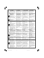
Symbols
WARNING
The following show
symbols used for the
machine. Be sure that
you understand their
meaning before use.
Symbole
WARNUNG
Die folgenden Symbole
werden für diese Maschine
verwendet. Achten Sie
darauf, diese vor der
Verwendung zu verstehen.
Symboles
AVERTISSEMENT
Les symboles suivants
sont utilisés pour l’outil.
Bien se familiariser avec
leur signification avant
d’utiliser l’outil.
Simboli
AVVERTENZA
Di seguito mostriamo i
simboli usati per la
macchina. Assicurarsi di
comprenderne il
significato prima dell’uso.
Read all safety
warnings and all
instructions.
Failure to follow the
warnings and
instructions may result
in electric shock, fire
and/or serious injury.
Always wear eye
protection.
Lesen Sie sämtliche
Sicherheitshinweise und
Anweisungen durch.
Wenn die Warnungen und
Anweisungen nicht befolgt
werden, kann es zu
Stromschlag, Brand und/
oder ernsthaften
Verletzungen kommen.
Lire tous les avertissements
de sécurité et toutes les
instructions.
Tout manquement à observer
ces avertissements et
instructions peut engendrer
des chocs électriques, des
incendies et/ou des blessures
graves.
Leggere tutti gli avvertimenti
di sicurezza e tutte le
istruzioni.
La mancata osservanza degli
avvertimenti e delle istruzioni
potrebbe essere causa di
scosse elettriche, incendi e/o
gravi lesioni.
Symbolen
WAARSCHUWING
Hieronder staan symbolen
afgebeeld die van toepassing
zijn op deze machine. U
moet de betekenis hiervan
begrijpen voor gebruik.
Símbolos
ADVERTENCIA
A continuación se muestran
los símbolos usados para la
máquina. Asegúrese de
comprender su significado
antes del uso.
Símbolos
AVISO
A seguir aparecem os
símbolos utilizados pela
máquina. Assimile bem
seus significados antes
do uso.
Lees alle waarschuwingen en
instructies aandachtig door.
Nalating om de
waarschuwingen en
instructies op te volgen kan in
een elektrische schok, brand
en/of ernstig letsel resulteren.
Draag altijd
oogbescherming.
Lea todas las instrucciones y
advertencias de seguridad.
Si no se siguen las
advertencias e instrucciones,
podría producirse una
descarga eléctrica, un
incendio y/o daños graves.
Utilice siempre una
protección ocular.
Leia todas as instruções e
avisos de segurança.
Se não seguir todas as
instruções e os avisos, pode
provocar um choque eléctrico,
incêndio e/ou ferimentos
graves.
Utilize sempre
protecção para os olhos.
Tragen Sie immer einen
Augenschutz.
Indossate sempre le
protezioni oculari.
Only for EU countries
Do not dispose of electric tools
together with household waste
material!
In observance of European
Directive 2002/96/EC on waste
electrical and electronic
equipment and its
implementation in accordance
with national law, electric tools
that have reached the end of
their life must be collected
separately and returned to an
environmentally compatible
recycling facility.
Nur für EU-Länder
Werfen Sie Elektrowerkzeuge
nicht in den Hausmüll!
Gemäss Europäischer
Richtlinie 2002/96/EG über
Elektro- und Elektronik-
Altgeräte und Umsetzung in
nationales Recht müssen
verbrauchte Elektrowerkzeuge
getrennt gesammelt und einer
umweltgerechten
Wiederververtung zugeführt
werden.
Pour les pays européens
uniquement
Ne pas jeter les appareils
électriques dans les ordures
ménagères!
Conformément à la directive
européenne 2002/96/EG relative
aux déchets d’équipements
électriques ou électroniques
(DEEE), et à sa transposition dans
la législation nationale, les
appareils électriques doivent être
collectés à part et être soumis à
un recyclage respectueux de
l’environnement.
Solo per Paesi UE
Non gettare le
apparecchiature elettriche tra i
rifiuti domestici.
Secondo la Direttiva Europea
2002/96/CE sui rifiuti di
apparecchiature elettriche ed
elettroniche e la sua
attuazione in conformità alle
norme nazionali, le
apparecchiature elettriche
esauste devono essere
raccolte separatamente, al fine
di essere reimpiegate in modo
eco-compatibile.
Alleen voor EU-landen
Geef elektrisch gereedschap niet
met het huisvuil mee!
Volgens de Europese richtlijn
2002/96/EG inzake oude
elektrische en elektronische
apparaten en de toepassing
daarvan binnen de nationale
wetgeving, dient gebruikt
elektrisch gereedschap
gescheiden te worden
ingezameld en te worden
afgevoerd naar een recycle
bedrijf dat voldoet aan de
geldende milieu-eisen.
Sólo para países de la Unión
Europea
¡No deseche los aparatos eléctricos
junto con los residuos domésticos!
De conformidad con la Directiva
Europea 2002/96/CE sobre residuos
de aparatos eléctricos y electrónicos
y su aplicación de acuerdo con la
legislación nacional, las
herramientas eléctricas cuya vida útil
haya llegado a su fin se deberán
recoger por separado y trasladar a
una planta de reciclaje que cumpla
con las exigencias ecológicas.
Apenas para países da UE
Não deite ferramentas
eléctricas no lixo doméstico!
De acordo com a directiva
europeia 2002/96/CE sobre
ferramentas eléctricas e
electrónicas usadas e a
transposição para as leis
nacionais, as ferramentas
eléctricas usadas devem ser
recolhidas em separado e
encaminhadas a uma
instalação de reciclagem dos
materiais ecológica.
Toujours porter des
verres de protection.
™‡Ì‚ÔÏ·
¶ƒ√™√Ã∏
Τα παρακάτω δείνυν τα
σύµλα πυ ρησιµπιύνται
στ µηάνηµα. Βεαιωθείτε τι
κατανείτε τη σηµασίας τυς
πριν τη ρήση.
¢È·‚¿˙ÂÙ fiϘ ÙȘ
ÚÔÂȉÔÔÈ‹ÛÂȘ ·ÛÊ·Ï›·˜ ηÈ
fiϘ ÙȘ Ô‰ËÁ›Â˜.
Η µη τήρηση των
πρειδπιήσεων και δηγιών
µπρεί να πρκαλέσει
ηλεκτρπληία, πυρκαγιά και/ή
σαρ τραυµατισµ.
Φράτε πάντα τν κατάλληλ
επλισµ για την πρστασία
των µατιών.
Mvo για τις ώρες της EE
Mηv πετάτε τα ηλεκτρικά
εργαλεία στov κάδo oικιακώv
απoρριµµάτωv!
Σύµ*ωvα µε τηv εuρωπαϊκή
oδηγία 2002/96/EK περί
ηλεκτρικώv και ηλεκτρovικώv
σuσκεuώv και τηv εvσωµάτωσή
της στo εθvικ δίκαιo, τα
ηλεκτρικά εργαλεία πρέπει vα
σuλλέγovται εωριστά και vα
επιστρέ*ovται για αvακύκλωση
µε τρπo *ιλικ πρoς τo
περιάλλov.
00Mark_CC14SF_WE 4/15/10, 17:324

5
English
GENERAL OPERATIONAL PRECAUTIONS
WARNING! When using electric tools, basic safety
precautions should always be followed to reduce the
risk of fire, electric shock and personal injury, including
the following.
Read all these instructions before operating this product
and save these instructions.
For safe operations:
1. Keep work area clean. Cluttered areas and benches
invite injuries.
2. Consider work area environment. Do not expose
power tools to rain. Do not use power tools in
damp or wet locations. Keep work area well lit.
Do not use power tools where there is risk to
cause fire or explosion.
3. Guard against electric shock. Avoid body contact
with earthed or grounded surfaces. (e.g. pipes,
radiators, ranges, refrigerators).
4. Keep children away. Do not let visitors touch the
tool or extension cord. All visitors should be kept
away from work area.
5. Store idle tools. When not in use, tools should
be stored in a dry, high or locked up place, out
of reach of children.
6. Do not force the tool. It will do the job better and
safer at the rate for which it was intended.
7. Use the right tool. Do not force small tools or
attachments to do the job of a heavy duty tool.
Do not use tools for purposes not intended; for
example, do not use circular saw to cut tree limbs
or logs.
8. Dress properly. Do not wear loose clothing or
jewellery, they can be caught in moving parts.
Rubber gloves and non-skid footwear are
recommended when working outdoors. Wear
protecting hair covering to contain long hair.
9. Always use eye and ear protection. Other personal
protective equipment such as dust mask, gloves,
helmet and apron should be worn when necessary.
When assessing the need for a face or dust mask
consideration should be given to the harmful
properties of both the material being grounded
or coated. If in doubt, wear the protective
equipment.
10. Connect dust extraction equipment.
If devices are provided for the connection of dust
extraction and collection facilities ensure these are
connected and properly used.
11. Do not abuse the cord. Never carry the tool by
the cord or yank it to disconnect it from the
receptacle. Keep the cord away from heat, oil and
sharp edges.
12. Secure work. Use clamps or a vise to hold the
work. It is safer than using your hand and it frees
both hands to operate tool.
13. Do not overreach. Keep proper footing and balance
at all times.
14. Maintain tools with care. Keep cutting tools sharp
and clean for better and safer performance. Follow
instructions for lubrication and changing
accessories. Inspect tool cords periodically and if
damaged, have it repaired by authorized service
center. Inspect extension cords periodically and
replace, if damaged. Keep handles dry, clean, and
free from oil and grease.
15. Disconnect tools. When not in use, before servicing,
and when changing accessories such as blades,
bits and cutters.
16. Remove adjusting keys and wrenches. Form the
habit of checking to see that keys and adjusting
wrenches are removed from the tool before turning
it on.
17. Avoid unintentional starting. Do not carry a
plugged-in tool with a finger on the switch. Ensure
switch is off when plugging in.
18. Use outdoor extension leads. When tool is used
outdoors, use only extension cords intended for
outdoor use.
19. Stay alert. Watch what you are doing. Use common
sense. Do not operate tool when you are tired.
20. Check damaged parts. Before further use of the
tool, a guard or other part that is damaged should
be carefully checked to determine that it will
operate properly and perform its intended function.
Check for alignment of moving parts, free running
of moving parts, breakage of parts, mounting and
any other conditions that may affect its operation.
A guard or other part that is damaged should be
properly repaired or replaced by an authorized
service center unless otherwise indicated in this
handling instructions. Have defective switches
replaced by an authorized service center. Do not
use the tool if the switch does not turn it on and
off.
21. Warning
The use of any accessory or attachment, other
than those recommended in this handling
instructions, may present a risk of personal injury.
22. Have your tool repaired by a qualified person.
This electric tool is in accordance with the relevant
safety requirements. Repairs should only be carried
out by qualified persons using original spare parts.
Otherwise this may result in considerable danger
to the user.
PRECAUTIONS ON USING CUT-OFF
MACHINE
1. Inspect the cutting wheel before use, do not use
chipped or otherwise defect cutting wheels. Always
make a trial run before use to confirm that the
Cut-off Machine does not involve abnormalities.
2. Use the normal cut-off wheel on its normal working
surface.
3. Guard against cut-off sparks.
4. Properly replace the cut-off wheel.
5. Always pay attention that the cut-off wheel
clamping parts are never impaired. Defective parts
will cause damage to the cut-off wheel.
6. Ensure that the workpiece is free of foreign matter
such as nails.
7. Use only cutting wheels recommended by the
manufacturer which have a marked speed equal
to or greater than the speed marked on the
nameplate of the machine.
8. Abrasive wheels shall be stored and handled with
care in accordance with manufacturer’s
instructions.
(Original instructions)
01Eng_CC14SF_WE 5/31/11, 14:405

6
English
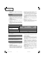
*Be sure to check the nameplate on product as it is subject to change by areas.
SPECIFICATIONS
STANDARD ACCESSORIES
(1) Cut-off wheel ............................................................. 1
(2) Hex. bar wrench ....................................................... 1
APPLICATION
Cutting of various metallic materials such as pipes, round
bars, shaped steel and siding board.
PRIOR TO OPERATION
1. Power source
Ensure that the power source to be utilized
conforms to the power requirements specified on
the product nameplate.
2. Power switch
Ensure that the power switch is in the OFF position.
If the plug is connected to a receptacle while the
power switch is in the ON position, the power tool
will start operating immediately, which could cause
a serious accident.
3. Extension cord
When the work area is removed from the power
source, use an extension cord of sufficient thickness
and rated capacity. The extension cord should be
kept as short as practicable.
4. Install the machine on a level flat place, and keep
it in a stable condition. Prior to shipping, the
equipment is subjected to a rigid factory inspection
to prevent electric shocks during operation.
5. Since movable portions are secured by tension of
a chain while in transit, remove the chain from
the chain hook by slightly depressing the switch
handle.
6. Ascertain that all cut-off wheels are in perfect
condition, and do not display scars and cracks.
7. Although they have been fully clamped at the
factory prior to delivery, reclamp the clamping
nuts securely for safety.
8. Possible accidents such as a cracked cut-off wheel
is prevented by this protective cover (wheel cover).
Voltage (by areas)*
Input
Max. cutting dimensions
90° 100 mm × 130 mm 70 mm × 235 mm
Height × width
45° 100 mm × 106 mm
Cut-off wheel ø355 × ø25.4 × 4 mm (Reinforced resinoid cut-off wheel)
No-Load Speed 3800 min
-1
Max. working peripheral speed 4800 m/min
Weight 17 kg
(110V, 115V, 120V, 127V)
(230V, 240V)
1640W* 2000W*
Although it has been fully clamped at the factory
prior to delivery, securely reclamp the mounting
screws for safety.
9. When replacing the cut-off wheel, ensure that the
replacement cutting wheel has a designed
circumferential speed in excess of 4800 m/min.
10. Ensure that the bar spanner used for tightening
or removing the cut-off wheel is not attached to
the machine.
11. Check that the work piece is properly supported.
Ensure that the material is securely fastened with
the vise. If it is not, a serious accident could be
caused if the material comes loose or the cut-off
wheel breaks during operation.
12. Ensure that the abrasive wheel is correctly fitted
and tightened before use and run the machine at
no-load for 30s in safe position, stop immediately
if there is a considerable vibration or if other
defects are detected. If this condition occurs, check
the machine to determine the cause.
13. Rotate the cut-off wheel to inspect any facial
deflection. A heavy deflection will cause the cut-
off wheel to shift.
14. Ensure that ventilation openings are kept clear
when working in dusty conditions. If it should
become necessary to clear dust, first disconnect
the machine from the mains supply.
CUTTING PROCEDURES
CAUTION
It is dangerous to remove or install the workpiece while
the cut-off wheel turning.
1. Operating the switch
The switch is switched on by manually pulling the
trigger and cut off by releasing the trigger to the
original location. The switch will not operate unless
the stopper has been pushed in.
2. Cutting
(1) Rotate the cut-off wheel, gently press down the
handle, and bring the cut-off wheel close to the
cutting material.
9. Ensure that mounted wheel are fitted in accordance
with the manufacture’s instructions.
10. Do never use the machine without the guard in
place.
11. Do not saw blade.
12. Do not use the machine in explosive atmospheres
and environments where sparks could fire,
explosion etc.
01Eng_CC14SF_WE 9/28/12, 8:566

7
English
(2) When the cut-off wheel contacts the cutting material,
gently press down the handle further and start
cutting.
(3) When cutting (or designated slotting) is completed,
raise the handle and restore it to its original position.
(4) At the termination of each cutting process, turn OFF
the switch to stop rotation and proceed with the
subsequent cutting job.
CAUTION
It does not necessarily cut rapidly when putting
more force on the handle.
Too much force on the handle will put excessive
pressure on the motor and reduce its capacity.
Do not fail to switch OFF the switch after operation
is completed and pull the plug out.
MOUNTING AND DISMOUNTING THE CUT-
OFF WHEEL
1. Dismounting the cut-off wheel (Fig. 2)
(1) Press the stopper and loosen the bolt with a hex.
bar wrench.
CAUTION
When the mounting shaft for cut-off wheel cannot
be fixed with pressing the stopper, turn the bolt
with a hex. bar wrench while pressing the stopper.
The mounting shaft for cut-off wheel is fixed when
the stopper has been lowered.
(2) Remove the bolt, washer (A), and the wheel washer
and detach the cut-off wheel.
2. Mounting the cut-off wheel
Throughly remove dust from the wheel washers
and bolt then mount the wheel by following the
dismounting procedures in reverse order. Be sure
to attach the sub-cover at the end.
CAUTION
Confirm that the stopper which was used for
installation and removal of the cut-off wheel has
returned to the retract position.
HOW TO OPERATE
1. Procedure for fixing the cutting material (Fig. 8
and 9)
Place the workpiece material between vise (A) and
vise (B), raise the clutch and push the screw handle
to bring vise (A) lightly into contact with the
workpiece material, as shown in Fig. 8.
Then, turn the clutch down, and securely fix the
workpiece material in position by turning the screw
handle. When the cutting job is completed, turn the
screw handle 2 or 3 times to loosen the vise, and
remove the workpiece material, as shown in
Fig. 9.
CAUTION
The wheel continues to rotate after the machine is
switched off.
Never remove or install a workpiece material while
the cut-off wheel is rotating, to avoid personal injury.
Long workpieces must be supported by blocks
nonflammable material on either side so that it be
level with the base top.
2. Cutting at angles (Fig. 3 and 4)
(1) The machine permits cutting at angles of 45° or 60°.
(2) Loosen the two M10 hexagon socket head bolts on
the vice (B), then set the working surface on the
vice-jaw at any angles of 0°, 30°, or 45° as shown
in Fig. 4. Upon completion of setting, securely tighten
the two 10 mm bolts.
(3) When wide material is cut with angle, it will be
firmly camped by fixing a steel board like Fig. 5
to the vise (B).
3. Moving the stationary vise-jaw (Fig. 6)
The vise opening is set at the maximum of 170 mm
when shipped from the factory. In case an opening
of more than 170 mm is required, move the vise
to the position shown by the chain line after
unscrewing the two bolts. The maximum opening
can be set in two steps 205 mm and 240 mm. When
the cutting material is excessively wide, the vise can
be effectively used by repositioning the stationary
side of the vise-jaws.
4. How to use metallic block (Fig. 7)
When the cut-off wheel has a reduced outer
diameter, insert between the vise (A) and (B) a
metallic block slightly smaller than the dimension
of workpiece being cut to use the cut-off wheel
economically.
MAINTENANCE AND INSPECTION
CAUTION
Be sure to switch off and pull off the plug from the power
outlet before inspection and maintenance.
1. Replacing a cut-off wheel
When the cut-off wheel has already become dull
while continually using, the unnecessary load is got
from the motor. Consequently, redress or replace
a dull cut-off wheel to ensure grinding efficiency.
2. Inspecting the carbon brushes (Fig. 10)
The Motor employs carbon brushes which are
consumable parts. When they become worn to or
near the “wear limit”, it could result in motor trouble.
When an auto-stop carbon brush is equipped, the
motor will stop automatically. At that time, replace
both carbon brushes with new ones which have the
same carbon brush Number shown in the figure.
In addition, always keep carbon brushes clean and
ensure that they slide freely within the brush holders.
3. Inspecting the mounting screws
Regularly inspect all mounting screws and ensure
that they are properly tightened. Should any of the
screws be loose, retighten them immediately. Failure
to do so could result in serious hazard.
4. Lubrication
Supply oil in the following oil supply points once
a month so as to keep the machine workable for
a long time (See Fig. 1).
Oil supply points
䡬 Rotary part of shaft
䡬 Rotary part of vise
䡬 Slide way of vise (A)
5. Cleaning
Wipe off chip and waste adhered to the machine
with a cloth or the like time to time. Be careful not
to make the motor portion wet with oil or water.
6. Faults in the machine, including guards or cutter
blades, should be reported as soon as they are
discovered.
01Eng_CC14SF_WE 4/15/10, 17:327

8
English
7. Service parts list
CAUTION
Repair, modification and inspection of Hitachi Power
Tools must be carried out by an Hitachi Authorized
Service Center.
This Parts List will be helpful if presented with the
tool to the Hitachi Authorized Service Center when
requesting repair or other maintenance.
In the operation and maintenance of power tools,
the safety regulations and standards prescribed in
each country must be observed.
MODIFICATIONS
Hitachi Power Tools are constantly being improved
and modified to incorporate the latest technological
advancements.
Accordingly, some parts may be changed without
prior notice.
GUARANTEE
We guarantee Hitachi Power Tools in accordance with
statutory/country specific regulation. This guarantee does
not cover defects or damage due to misuse, abuse, or
normal wear and tear. In case of complaint, please send
the Power Tool, undismantled, with the GUARANTEE
CERTIFICATE found at the end of this Handling
instruction, to a Hitachi Authorized Service Center.
NOTE:
Due to HITACHI’s continuing program of research and
development, the specifications herein are subject to
change without prior notice.
IMPORTANT
Correct connection of the plug
The wires of the mains lead are coloured in accordance
with the following code:
Blue: -Neutral
Brown: -Live
As the colours of the wires in the mains lead of this tool
may not correspond with the coloured markings
identifying the terminals in your plug proceed as follows:
The wire coloured blue must be connected to the terminal
marked with the letter N or coloured black. The wire
coloured brown must be connected to the terminal
marked with the letter L or coloured red. Neither core
must be connected to the earth terminal.
NOTE:
This requirement is provided according to BRITISH
STANDARD 2769: 1984.
Therefore, the letter code and colour code may not be
applicable to other markets except The United Kingdom.
Information concerning airborne noise and vibration
The measured values were determined according to
EN61029.
The typical A-weighted sound pressure level: 99 dB (A)
The typical A-weighted sound power level: 107 dB (A)
Wear hearing protection.
Vibration total values (triaxial vector sum) determined
according to EN61029.
Cutting steel bar:
Vibration emission value
ah = 6.6 m/s
2
Uncertainty K = 1.5 m/s
2
The declared vibration total value has been measured in
accordance with a standard test method and may be
used for comparing one tool with another.
It may also be used in a preliminary assessment of
exposure.
WARNING
䡬 The vibration emission during actual use of the
power tool can differ from the declared total value
depending on the ways in which the tool is used.
䡬 Identify safety measures to protect the operator that
are based on an estimation of exposure in the
actual conditions of use (taking account of all parts
of the operating cycle such as the times when the
tool is switched off and when it is running idle in
addition to the trigger time).
䢇 Information about power supply system of nominal
voltage 230 V~
Under unfavorable mains conditions, this power tool
may cause
transient voltage drops
or
interfering voltage
fluctuations
.
This power tool is intended for the connection to a
power supply system with a maximum permissible sys-
tem impedance Z
MAX
of 0.14 Ohm at the interface point
(power service box) of the user's supply.
The user has to ensure that this power tool is connected
only to a power supply system which fulfills the require-
ment above.
If necessary, the user can ask the public power supply
company for the system impedance at the interface point.
䢇 Information about the circuit-breaker switch of
nominal voltage 230 V~
This tool should be used only if it is connected to a 16 A
Fuse with gl disconnection characteristic.
01Eng_CC14SF_WE 5/31/11, 14:408
Page is loading ...
Page is loading ...
Page is loading ...
Page is loading ...
Page is loading ...
Page is loading ...
Page is loading ...
Page is loading ...
Page is loading ...
Page is loading ...
Page is loading ...
Page is loading ...
Page is loading ...
Page is loading ...
Page is loading ...
Page is loading ...
Page is loading ...
Page is loading ...
Page is loading ...
Page is loading ...
Page is loading ...
Page is loading ...
Page is loading ...
Page is loading ...
Page is loading ...
Page is loading ...
Page is loading ...
Page is loading ...
Page is loading ...
Page is loading ...
Page is loading ...

40
09Back_CC14SF_WE 4/15/10, 17:3440

41
09Back_CC14SF_WE 4/15/10, 17:3441

42
ITEM
PART NAME
NO.
1 FLANGE BOLT (B)
2 SUB COVER (B)
3 BOLT WASHER M8
4 SUB COVER (A)
5 NUT M5
6 MACHINE SCREW (W/WASHERS) M5 × 16
7 FLANGE BOLT (A)
8 COVER SPACER
11 HEX. SOCKET HD.BOLT M10 × 20
12 WASHER (A)
13 WHEEL WASHER (A)
14 CUT-OFF WHEEL ASS'Y
15 DESIGN COVER
16 MACHINE SCREW M5 × 12
17 SPRING WASHER M5
18 COVER BUSH
19 WHEEL COVER (A)
21 BOLT WASHER M5
25 BOLT WASHER M10
26 SPINNDLE ASS'Y
27 BALL BEARING 6306ZZCM
28 BEARING PLATE
29 BALL BEARING
30 SEAL LOCK HEX. SOCKET SET SCREW M5 × 16
31 CHAIN HOOK
32 GEAR CASE
33 BALL BEARING 6002VVCM
34 RETAINING RING FOR D15 SHAFT
35 ARMATURE
36 FAN GUIDE
37 BALL BEARING
38 GAUGE SPRING
39 RETAINING RING (E-TYPE) FOR D6 SHAFT
40 STOPPER PIN
41 TUBE(D)
42 HEX. HD. TAPPNG SCREW D5 × 75
43 STATOR ASS'Y
44 BRUSH TERMINAL
45 MACHINE SCREW (W/WASHERS) M5 × 35
46 NAME PLATE
47 HOUSING ASS'Y
48 HEX. E5SOCKET SET SCREW M5 × 8
49 BRUSH HOLDER
50 CARBON BRUSH
51 BRUSH CAP
52 SPRING
53 HANDLE
54 SWITCH
55 TAPPING SCREW (W/FLANGE)
56 CONNECTOR
57 NOISE SUPPRESSOR
58 TERMINAL
59 INTERNAL WIRE
60 HANDLE COVER
ITEM
PART NAME
NO.
61 TAPPING SCREW (W/FLANGE) D4 × 16
63 TUBE(D)
64 CORD CLIP
65 TAPPING SCREW (W/FLANGE) D4 × 16
66 CORD ARMOR
67 CORD
68 VISE ASS'Y
69 SCREW
70 SCREW HOLDER
71 HEX. SOCKET HD. BOLT (W/WASHERS) M8 × 25
72 CHAIN
73 BOLT WASHER M8
74 BOLT
75 SPLIT PIN D3 × 15
76 WASHER M16
77 ROLL PIN D5 × 25
78 VISE (B)
79 HINGE SHAFT
80 BASE RUBBER
81 BASE
82 NUT M8
83 SPRING WASHER M8
84 SPARK CHUTE
85 HEX. SOCKET HD. BOLT M8 × 20
501 HEX. BAR WRENCH 8MM
09Back_CC14SF_WE 4/15/10, 17:3442

43
09Back_CC14SF_WE 4/15/10, 17:3443

44
English
Nederlands
GUARANTEE CERTIFICATE
1 Model No.
2 Serial No.
3 Date of Purchase
4 Customer Name and Address
5 Dealer Name and Address
(Please stamp dealer name and address)
Italiano Ελληνικά
Français Português
Deutsch
Español
GARANTIEBEWIJS
1 Modelnummer
2 Serienummer
3 Datum van aankoop
4 Naam en adres van de gebruiker
5 Naam en adres van de handelaar
(Stempel a.u.b. naam en adres vande de
handelaar)
GARANTIESCHEIN
1 Modell-Nr.
2 Serien-Nr.
3 Kaufdaturn
4 Name und Anschrift des Kunden
5 Name und Anschrift des Händlers
(Bitte mit Namen und Anschrift des
Handlers abstempeln)
CERTIFICADO DE GARANTIA
1 Número de modelo
2 Número de serie
3 Fecha de adquisición
4 Nombre y dirección del cliente
5 Nombre y dirección del distribudor
(Se ruega poner el sellú del distribudor
con su nombre y dirección)
CERTIFICAT DE GARANTIE
1 No. de modèle
2 No. de série
3 Date d'achat
4 Nom et adresse du client
5 Nom et adresse du revendeur
(Cachet portant le nom et l'adresse du
revendeur)
CERTIFICADO DE GARANTIA
1 Número do modelo
2 Número do série
3 Data de compra
4 Nome e morada do cliente
5 Nome e morada do distribuidor
(Por favor, carímbe o nome e morada
do distribuidor)
CERTIFICATO DI GARANZIA
1 Modello
2 N° di serie
3 Data di acquisto
4 Nome e indirizzo dell'acquirente
5 Nome e indirizzo del rivenditore
(Si prega di apporre il timbro con questi
dati)
¶π™∆√¶√π∏∆π∫√ ∂°°À∏™∏™
1 Αρ. Μντέλυ
2 Αύων Αρ.
3 Ηµερµηνία αγράς
4 ΄νµα και διεύθυνση πελάτη
5 ΄νµα και διεύθυνση µεταπωλητή
(Παρακαλύµε να !ρησιµπιηθεί
σ"ραγίδα)
✄
09Back_CC14SF_WE 4/15/10, 17:3444

45
1
2
3
4
5
✄
09Back_CC14SF_WE 4/15/10, 17:3445

46
Hitachi Power Tools Europe GmbH
Siemensring 34, 47877 willich 1, F. R. Germany
Tel: +49 2154 49930
Fax: +49 2154 499350
URL: http://www.hitachi-powertools.de
Hitachi Power Tools Netherlands B. V.
Brabanthaven 11, 3433 PJ Nieuwegein, The Netherlands
Tel: +31 30 6084040
Fax: +31 30 6067266
URL: http://www.hitachi-powertools.nl
Hitachi Power Tools (U. K.) Ltd.
Precedent Drive, Rooksley, Milton Keynes, MK 13, 8PJ, United Kingdom
Tel: +44 1908 660663
Fax: +44 1908 606642
URL: http://www.hitachi-powertools.co.uk
Hitachi Power Tools France S. A. S.
Prac del’ Eglantier 22, rue des Crerisiers Lisses, C. E. 1541,
91015 EVRY CEDEX, France
Tel: +33 1 69474949
Fax: +33 1 60861416
URL: http://www.hitachi-powertools.fr
Hitachi Power Tools Belgium N.V. / S.A.
Koningin Astridlaan 51, 1780 Wemmel, Belgium
Tel: +32 2 460 1720
Fax: +32 2 460 2542
URL http://www.hitachi-powertools.be
Hitachi Fercad Power Tools Italia S.p.A
Via Retrone 49-36077, Altavilla Vicentina (VI), Italy
Tel: +39 0444 548111
Fax: +39 0444 548110
URL: http://www.hitachi-powertools.it
Hitachi Power Tools lberica, S.A.
C / Migjorn, s/n, Poligono Norte, 08226 Terrassa, Barcelona, Spain
Tel: +34 93 735 6722
Fax: +34 93 735 7442
URL: http://www.hitachi-powertools.es
Hitachi Power Tools Österreich GmbH
Str. 7, Objekt 58/A6, Industriezentrum NÖ –Süd 2355
Wiener Neudorf, Austria
Tel: +43 2236 64673/5
Fax: +43 2236 63373
09Back_CC14SF_WE 4/15/10, 17:3446

210
Code No. C99142276 F
Printed in China
Hitachi Koki Co., Ltd.
Representative office in Europe
Hitachi Power Tools Europe GmbH
Siemensring 34, 47877 Willich 1, F. R. Germany
Technical file at:
Hitachi Koki Europe Ltd.
Clonshaugh Business & Technology Park, Dublin 17, lreland
Head office in Japan
Hitachi Koki Co., Ltd.
Shinagawa Intercity Tower A, 15-1, Konan 2-chome,
Minato-ku, Tokyo, Japan
Nederlands
EC VERKLARING VAN CONFORMITEIT
Wij verklaren onder eigen verantwoordelijkheid dat dit
product conform de richtlijnen of gestandardiseerde
documenten EN61029, EN55014 en EN61000 voldoet aan
de eisen van bepalingen 2004/108/EC en 2006/42/EC. Dit
product voldoet ook aan de RoHS-richtlijn 2011/65/EU.
De manager voor Europese normen van Hitachi Koki
Europe Ltd. heeft de bevoegdheid tot het samenstellen van
het technische bestand.
Deze verklaring is van toepassing op produkten voorzien
van de CE-markeringen.
Español
DECLARACIÓN DE CONFORMIDAD DE LA CE
Declaramos bajo nuestra única responsabilidad que este
producto está de acuerdo con las normas o con los
documentos de normalización EN61029, EN55014 y
EN61000, según indican las Directrices 2004/108/CE y
2006/42/CE. Este producto satisface también los requisitos
establecidos por la Directiva 2011/65/EU (RoHS).
El Jefe de Normas Europeas de Hitachi Koki Europe Ltd.
está autorizado para recopilar archivos técnicos.
Esta declaración se aplica a los productos con marcas
de la CE.
Português
DECLARAÇÃO DE CONFORMIDADE CE
Declaramos, sob nossa única e inteira responsabilidade,
que este produto está de acordo com as normas ou
documentos normativos EN61029, EN55014 e EN61000,
em conformidade com as Directrizes 2004/108/CE e 2006/
42/CE. Este produto está também em conformidade com
a Directiva RoHS 2011/65/EU.
O Gestor de Normas Europeias da Hitachi Koki Europe Ltd.
está autorizado a compilar o ficheiro técnico.
Esta declaração se aplica aos produtos designados CE.
Ελληνικά
EK ∆ΗΛΩΣΗ ΕΝΑΡΜΝΙΣΜΥ
∆ηλώνυµε µε απλυτη υπευθυντητα τι αυτ τ πριν
είναι εναρµνισµέν µε τα πρτυπα ή τα έγρα$α
δηµιυργίας πρτύπων EN61029, EN55014 και EN61000
σε συµ$ωνία µε τις δηγίες 2004/108/EK και 2006/42/EK.
Αυτ τ πρϊν συµµρ$ώνεται επίσης µε την δηγία
RoHS 2011/65/ΕU.
υπεύθυνς για τα ευρωπαϊκά πρτυπα στην Hitachi Koki
Europe Ltd. είναι ε*υσιδτηµένς να συντάσσει τν
τε+νικ $άκελ.
Αυτή η δήλωση ισ+ύει στ πριν µε τ σηµάδι CE.
English
EC DECLARATION OF CONFORMITY
We declare under our sole responsibility that this product
is in conformity with standards or standardization
documents EN61029, EN55014 and EN61000 in
accordance with Directives 2004/108/EC and 2006/42/EC.
This product also conforms to RoHS Directive 2011/65/
EU.
The European Standards Manager at Hitachi Koki Europe
Ltd. is authorized to compile the technical file.
This declaration is applicable to the product affixed CE
marking.
Deutsch
EG-KONFORMITÄTSERKLÄRUNG
Wir erklären mit alleiniger Verantwortung, dass dieses
Produkt den Standards oder
Standardisierungsdokumenten EN61029, EN55014 und
EN61000 in Übereinstimmung mit den Direktiven 2004/
108/EG und 2006/42/EG entspricht. Dieses Produkt stimmt
auch mit der RoHS-Richtlinie 2011/65/EU überein.
Der Manager für europäische Standards bei der Hitachi Koki
Europe Ltd. ist zum Verfassen der technischen Datei befugt.
Diese Erklärung gilt für Produkte, die die CE-Markierung
tragen.
Français
DECLARATION DE CONFORMITE CE
Nous déclarons sous notre seule et entière responsabilité
que ce produit est conforme aux normes ou documents
de normalisation EN61029, EN55014 et EN61000 en
accord avec les Directives 2004/108/CE et 2006/42/CE. Ce
produit est aussi conforme à la Directive RoHS 2011/65/
EU.
Le responsable des normes européennes d’Hitachi Koki
Europe Ltd. est autorisé à compiler les données techniques.
Cette déclaration s’applique aux produits désignés CE.
Italiano
DICHIARAZIONE DI CONFORMITÀ CE
Dichiariamo sotto nostra responsabilità che questo
prodotto è conforme agli standard o ai documenti sulla
standardizzazione EN61029, EN55014 e EN61000 in
conformità alle Direttive 2004/108/CE e 2006/42/CE. Il
prodotto è inoltre conforme alla direttiva RoHS 2011/
65/EU.
Il Responsabile delle Norme Europee di Hitachi Koki Ltd.
è autorizzato a compilare la scheda tecnica.
Questa dichiarazione è applicabile ai prodotti cui sono
applicati i marchi CE.
31. 10. 2012
F. Tashimo
Vice-President & Director
09Back_CC14SF_WE 9/28/12, 9:0747
-
 1
1
-
 2
2
-
 3
3
-
 4
4
-
 5
5
-
 6
6
-
 7
7
-
 8
8
-
 9
9
-
 10
10
-
 11
11
-
 12
12
-
 13
13
-
 14
14
-
 15
15
-
 16
16
-
 17
17
-
 18
18
-
 19
19
-
 20
20
-
 21
21
-
 22
22
-
 23
23
-
 24
24
-
 25
25
-
 26
26
-
 27
27
-
 28
28
-
 29
29
-
 30
30
-
 31
31
-
 32
32
-
 33
33
-
 34
34
-
 35
35
-
 36
36
-
 37
37
-
 38
38
-
 39
39
-
 40
40
-
 41
41
-
 42
42
-
 43
43
-
 44
44
-
 45
45
-
 46
46
-
 47
47
-
 48
48


Hitachi CC 14SF Handling Instructions Manual
- Category
- Power tools
- Type
- Handling Instructions Manual
Ask a question and I''ll find the answer in the document
Finding information in a document is now easier with AI
in other languages
- italiano: Hitachi CC 14SF
- français: Hitachi CC 14SF
- español: Hitachi CC 14SF
- Deutsch: Hitachi CC 14SF
- Nederlands: Hitachi CC 14SF
- português: Hitachi CC 14SF
Related papers
-
Hitachi CC 14SF Handling Instructions Manual
-
-
Hitachi C 10FCH Owner's manual
-
Hitachi CN 16 Handling Instructions Manual
-
-
-
Hitachi G23SE Owner's manual
-
Hitachi C 8FSHE Handling Instructions Manual
-
Hitachi CC 14SE User manual
-