Page is loading ...

ADJUSTING
BURNER FLAMES
1. Turn all burners full on and check
the flames. They should be blue in
color with some yellow tipping at
the ends of the flame. Foreign
particles in the gas line may cause
an orange flame at first, but this
will soon disappear.
NOTE: For the 18,000 BTU/HR
burner (on some models) the
cooktop burner knob should be
turned to the setting before the
lowest setting. This will ensure
that the entire burner is operating.
2. Turn the cooktop burner knob to
the lowest setting while observing
the flame.
Adjust the low flame setting using
the valve bypass screw as follows:
Low-setting adjustments must be
made with two other burners in
operation on a medium setting.
This prevents the low flame from
being set too low, resulting in the
flame being extinguished when
other burners are turned on.
3. To adjust
the flame,
remove the
knobs. Insert
a screwdriver
through the
access hole in
valve switch.
Engage
adjustment
screw in valve.
Refer to the
illustration
at right that
matches the
adjustment
screw location
for your model.
a. If the flames were too small or
fluttered, open the valve more
than the original setting.
b. If the flames blew away from the
burner, close the valve more than
the original setting.
4. Make the adjustment by slowly
turning the screw until flame
appearance is correct.
5. Testing flame stability:
Test 1 – Turn the knob from “HI”
to the lowest setting quickly. If the
flame goes out at the lowest setting,
increase the flame size and test again.
Test 2 – With the burner on the
lowest setting, open and close the
cabinet door under the cooktop.
If the flame is extinguished by the
air currents created by the door
movement, increase the flame
height and test again.
6. Flame recheck:
After the adjustment is made, turn
all burners off. Ignite each burner
individually. Observe the flame at
the “HI” position. Rotate the valve
to the lowest setting and be sure that
the flame size decreases as the valve
is rotated counterclockwise.
TO CONVERT THE COOKTOP BACK
TO NATURAL GAS, REVERSE THE
STEPS UNDER MAKING THE L.P.
CONVERSION.
L.P. CONVERSION
INSTRUCTIONS
Tools you will need:
Once the conversion is complete
and checked ok, fill out the LP
sticker and include your name,
organization and date conversion
was made. Apply the sticker near
the cooktop gas inlet opening to
alert others in the future that this
appliance has been converted to
LP. If converting back to natural
gas from LP, please remove
the sticker so others know the
appliance is set to use natural gas.
Safety Glasses
Small Flat-Head
Screwdriver
(4mm or 5/32″ tip size,
60mm long)
Phillips Head
Screwdriver
Pliers
7mm Nutdriver
No. 15 Torx-Head
Driver
Pub. No. 31-10600-1
(01-05 JR)

The L.P. orifice spuds for the cooktop
burners can be located within the
literature package attached to the
pressure regulator.
WARNING: This conversion must be
performed by a qualified installer or
gas supplier in accordance with the
manufacturer’s instructions and all codes
and requirements of the authority having
jurisdiction. Failure to follow instructions
could result in serious injury or property
damage. The qualified agency performing
this work assumes responsibility for the
conversion.
To adjust your cooktop for use with L.P.
gas, follow these instructions:
1. Disconnect all electrical power, at the
main circuit breaker or fuse box.
2. Shut off the gas supply to the cooktop
by closing the manual shut-off valve.
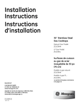
3. Adjust the Pressure Regulator:
a. Unscrew the cap.
b. Place your thumb against the flat side
of the spring retainer and press down
to remove the retainer.
c. Carefully look at the spring retainer to
locate the NAT or LP position.
d. Turn the spring retainer over so that LP
is showing on the bottom.
e. Snap the retainer back into position.
f. Screw the cap back onto the regulator.
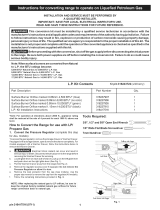
4. Change the cooktop burner orifices:
a. Remove the top grates, burner caps
and burner head.
b. Remove the spark igniter from the
burner base (if required to access
orifices). Use a No. 15 torx head driver
bit to remove the screws holding the
burner base in position.
c. Using a 7mm nut driver, remove the
top burner orifices. These may be
accessed through the hole in the
maintop.
NOTE: The orifices have a spring loaded
retaining ring around the hex head to
hold the orifice in the nut driver during
installation and removal. A slight amount
of force is required to push the nut driver
down over the ring.
IMPORTANT:
Save the orifices
removed from the
appliance for future
use.
5. Locate the L.P./Propane orifices.
Remove the orifices from the bracket.
The L.P./Propane orifices are shipped in
the literature package. They will have
a digit number and the letter “L” on
one side. (IMPORTANT: Save the
orifices removed from the appliance
for future use.)
Each orifice will also show a series of
engraved marks, (I, II, III, X, or none),
located on the top.
These marks denote the precise
location of each orifice to the cooktop
burner.
18,000 BTU/HR Burner (on some models)
The 18,000 BTU/HR burner has 2 orifices
with markings located on the side only.
(See rating plate on bottom of cooktop.)
NOTE: The main orifice is located low in
the center of the burner while the simmer
orifice is located higher behind the center
of the burner.
Units with 5 burners
Units with 4 burners
6. Install the L.P./Propane orifices in their
precise locations.
7. Replace the burner bases, heads, caps,
and top grates.
NOTE: When reattaching the burner
bases to glass top units, tighten to
10 in. lbs. max. torque.
8. Return the orifices to the bracket and
reattach the bracket with instruction
sheet to the pressure regulator using
the screw previously removed
.
CAUTION: The counter unit, as
shipped from the factory, is set for
use with natural gas. If you wish
to use your unit with Liquefied
Petroleum (Propane) gas, you
must first replace the orifices and
convert the pressure regulator.
CAUTION: The following
adjustments must be made before
turning on the burner. Failure
to do so could result in serious
injury. Be sure pressure regulator
has been converted.
DOWN
FOR OFF
NAT
LP
LP
NAT
LP
NAT
NAT
LP
Cap
Gasket
Spring
Retainer
L.P.
Position
Nat.
Position
Pressure Regulator
I II III
X
Retainer
Ring
See
table
See
table
See
table
See
table
See
table
conversion continued
Burner cap
Burner
head
Burner
base
Spark igniter
Burner
cap
Burner
head
Burner
base
Spark
igniter
18,000 BTU Burner
(on some models)
Remove
This
Assembly
Orifice Spud Located
Through This Opening
Rear left Front left Front right
Model orifice orifice orifice
JGP328 II II II
JGP628
JGP330 II II III
JGP933 III II X
JGP940 III III X
JGP945 III II
Simmer
orifice
Main
orifice
Front left Front right
Model burner orifice burner orifice
JGP630 II III
JGP963 III X
JGP970
ZGU36K
JGP975 III Replace: With:
Main
206X N
➔
108 X L
Simmer 57N ➔ 34L
Replace: With:
Main 206X N ➔ 108 X L
Simmer 57N ➔ 34L
/