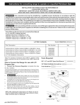
Frigidaire CRG3480ISSE Installation guide

Type
Installation guide
GRLP3 CONVERSION KiT APPLiCATiON iNSTRUCTiONS
INSTALLATION AND SERVICE MUST BE PERFORMED BY
A QUALIFIED INSTALLER.
IMPORTANT: SAVE FOR LOCAL ELECTRICAL INSPECTOR'S USE.
READ AND SAVE THESE INSTRUCTIONS FOR FUTURE REFERENCE.
I_ This conversion kit must be installed by a qualified service technician in accordance with the
manufacturer's instructions and all applicable codes and requirements of the authority having jurisdiction.
Failure to follow instructions may result in fire, explosion or production of carbon monoxide causing property
damage, personal injury or loss of life. The qualified service agency is responsible for the proper installation of
this kit. The installation is not proper and complete until the operation of the converted appliance is checked as
specified in the manufacturer's instructions supplied with this kit.
Before proceeding with the conversion, shut off the gas supply and disconnect the electrical
power to the range. Be sure both power supplies are off before installing the conversion kit. Failure to do so
could cause serious bodily injury.
IMPORTANT: Do not attempt to use this conVersion kit on products for which itis not specifically
designated: Consult the product installation manual or parts list to determine the correct conversion
kit number prior to use.
Tools Required for L.P. Conversion"
(A) 3/8", 1/2" and 5/8" Open End Wrench, (B) #1 Square Tip Screwdriver,
(C) 1/8" Wide Flat Blade Screwdriver, (D) 7rnm & 3/16" Nutdriver
A--_ B--_
C-_ D-__
How to Convert the Range for use with LP/Propane Gas
1. Convert the Pressure Regulator
To access the gas regulator, remove the storage drawer or warmer drawer. If equipped with a storage drawer, open and remove the drawer completely. For
models equipped with a front panel, remove the front panel and skip steps b & c below. For models equipped with warmer drawer, follow all the instructions
below to remove the warmer drawer. NOTE: DO NOT ATTEMPT TO CONVERT MODELS THAT FEATURE A LOWER OVEN.
a. _ Electrical Shock Hazard can occur and result in serious injury or death. Disconnect electrical power to the range
before removing the warmer drawer for servicing.
b. Locate glide lever on each side of drawer, pull up on the left glide lever and push down on the right glide lever (See Fig. 1).
c. Pull the drawer away from the range (See Fig. 2).
........ _ ,:;:,2_ ................... _,_:: _ .........
Pull up with finger
Left Glide
Pushdown with finger
[]
Fig. 1
p/n 316417518 rev F (1008)
Fig. 2
( Continued on following page )
After removing the drawer identify which type of regulator is installed on the range by comparing to
the photos below. Follow the appropriate conversion instructions found on the following pages.
Hex Shaped Cap
Aluminum Top I
Fig. 3 Aluminum Regulator i
Plastic Dust Protector I
I Fig. 4 Steel Top Regulator I
iNSTRUCTiONS FOR CONVERTING ALUMINUM REGULATOR:
If the regulator has an aluminum top as pictured in Fig. 3 convert the regulator in the following manner:
A. Remove the regulator access cover if equipped. Do not remove the Pressure Regulator or allow it to turn.
B. Unscrew the hex shaped cap and turn it over to access the conversion plug inside the cap. (Fig A)
Do not remove the spring from the regulator.
C. Rotate the plug 90 degrees in either direction to align the tabs on the plug with the notches in the cap. (Fig. B)
Lift the plug out of the cap.
D. Turn the plug over so that the
nib on then end of the cap faces
out and re insert into the cap.
Rotate the plug 90 degrees in
either direction to lock it into the
cap (Fig C)
E. Reinstall the cap and plug
securely onto the regulator.
F. Attach the LP conversion label
as illustrated on page 8 then
complete the remaining steps in
the instructions provided with
the LP kit.
i CONVERSION PLUG [ TO UNLOCK J
REINSTALL PLUG
WITH NIB POINTING UP
INSTRUCTIONS FOR CONVERTING STEEL TOP REGULATOR: If the regulator has a steel top as pictured in Fig. 4 above
convert the regulator in the following manner:
A. Remove the regulator access cover if equipped. Do not remove the Pressure Regulator or allow it to turn.
B. Remove the plastic dust protector from the cap (Fig 5). Using a 5/8" wrench, unscrew the cap from the pressure regulator (Fig 6).
Do not remove the spring from the regulator.
C. Turn the cap over so the hollow end faces outward. Place the solid end of the cap into the loop end of the dust protector
(See Fig. 7).
D. Replace the cap on the regulator with the hollow end facing out (Fig 8). Do not over tighten the cap. Snap the dust protector over
the regulator cap.
E. Attach the LP conversion label as illustrated on page 8 then complete the remaining steps in the instructions provided with the LP
kit.
NOTE: The pressure regulator cap
may be made d brass or aluminum
depending on the age of the
product. The conversion process is
the same for both types of caps.
2.Convert Surface Burners for use with LP/Propane Gas
This conversion kit contains multiple gas orifices for converting different styles of sealed gas surface burners. Determine
which style of gas surface burner is being converted and select the proper orifice from the designated orifice pack for that
jspecific burner styJe and size.
lSave the natural gas orifices removed from the appliance for possible future conversions to natural gas.
BURNER STYLE #1 (Non Mounted Burner) NoMountingScrews J
This burner style is not secured to the cooktop with screws and the burner head
l
can be lifted off the cooktop to access the orifice holder and orifice. The orifice
holder for this style of burner passes through a circular cut out in the cooktop as '_
seen in the photo. I _ _+_This style of burner will use the orifices contained in the main envelope of the
converting this burner style.
BURNER STYLE #2 (Screw Mounted Burner)
This burner is secured to the cooktop surface by two screws as seen in the photo.
The screw heads may be different than those illustrated. When the burner is
removed the orifice holder cutout in the cooktop can be seen to have an irregular
elongated shape. The mounting screw sockets for the burner head are also
visible. This style of burner will use the orifices contained in the separate smaller
envelope found inside the main envelope of the LP kit # GRLP3. This envelope
will be labeled " SCREW MOUNTED BURNER LP KIT". Follow the instructions on
page 4 when converting this burner style.
BURNER STYLE #3 (Screw Mounted Burner)
This burner can be identified by the two piece cap as seen in the photo. It is
secured to the cooktop surface by two screws. The screw heads may be different
than those illustrated. When the burner is removed three orifice openings can
be seen in the cooktop. This style of burner will use the orifices contained in the
separate smaller envelope found inside the main envelope of the LP kit # GRLP3.
This envelope will be labeled " SCREW MOUNTED BURNER LP KIT". Follow the
instructions on page 5 when converting this burner style.
OVAL BURNERS
There are currently two different oval surface burners used and each one requires
a different LP orifice. Both burners are rated 9500 BTU and are very similar in
appearance when the burner caps are in place. Use the photos at right to identify
which oval burner is on your range and use the appropriate orifice for that burner
when converting.
Oval Burner A - Use orifice size .89 from the main envelope. The orifice holder
for this burner will have the circular cooktop opening as seen in Burner Style #1.
Oval Burner B - Use orifice size .93 from envelope labeled " SCREW MOUNTED
BURNER LP KIT". The orifice holder for this burner will have the elongated
cooktop opening as seen in Burner Style #2.
NOTE: Some ranges may include multiple burner styles. When this is
encountered use the appropriate orifice for each burner styJe and size.
BURNER STYLE #1
Burner Secured With Screws Elongated Cooktop Opening
BURNER STYLE #2
Burner Secured With Screws J
BURNER STYLE #3
Oval Burner B
Top View Bottom View
BURNER STYLE #1 CONVERSION INSTRUCTIONS
Use caution when replacing each burner cap
so the electrode is not damaged.
Example of Burner Assembly
letter
located f__
inside _._ ,
Burner _ J=l_:_;_ _,_._
Head _//_
B .....
Head i i_':g& _ :!i
theMatchletter
stamped ( t j) _r_ elect1\ ;ode
on Burner \ _> J
Skirt with _Bumer Skirt
Burner Head _ .........
and Burner Cap
B = 9.5k
D=12k
E = 14 or 14,2k
B = 9.5k
Top View Bottom View
Unlike the standard gas range,
THIS COOKTOP ISNOT REMOVABLE.
Do not attempt to remove this cooktop.
B = 9.5k
(some models)
A= 5k
B = 9.5k
_=.._Round Or Oval Center Burner --
B = 9.5k
D = 12k
E = 14 or 14.2k
F = 16 or 16.2
B _=&,Sk
( Continued on page 4 )
( Continued from page 3 )
Unlike the standard gas range
THIS COOKTOP IS NOT REMOVABLE.
Do not attempt
to remove this cooktop.
GAS SURFACE BURNER ORIFICE DATA CHART (Burner Style #1)
BTU Rating / Natural Gas 5,000 9,500 12,000 14,000 16,000
Natural Gas Orifice 1.01 1.54 1.75 1.93 1.99
LP Gas Orifice .68 .89 .95 1.01 1.15
LP Orifice Marking Color Blue None Green Red Black
BTU Rating / LP Gas 4,500 8,000 10,000 11,000 14,000
_*Note: For at elevations above 2000operation
ft.,
appliance rating
_shall be reduced at the rate of 4 percent for each 1000 ft. above sea
level.
For all burner locations:
a. Remove the top grates and burner caps (See Fig. 10).
b. Lift off the burner heads.
i Fig. 10
Burner
Burner
Head
Do Not _
R..... 7 Electrode Fig. 11
7mm
Nut
Driver
c. Remove the factory installed natural gas orifices one at a time from the center of the orifice holder using a 7 mm nutdriver (See Fig. 11).
Remember to keep the original Natural Gas Orifices for later conversion to Natural Gas.
d. Replace the orifice with the correct LP/Propane gas orifice (See the Surface Burner Orifice Data Chart ; also refer to Fig 9 for the
correct LP orifice installation at each of the surface burner locations). Tighten each orifice until snug. Use caution not to overtighten.
Repeat for each surface burner.
e. Replace the burner heads. Match letter located under center of Burner Caps with letter located inside Burner Heads. Match the letter
stamped on Burner Skirt with Burner Head and Burner Cap. (Refer to Fig. 9). Be sure burner heads mate correctly with each surface
igniter, then replace the burner caps and burner grates.
Unlike the standard
gas range,
THIS COOKTOP IS
NOT REMOVABLE.
BURNER STYLE #2 CONVERSION INSTRUCTIONS
Use caution when replacing each burner cap so the electrode is not damaged.
Do not attempt
to remove this
cooktop. Fig. 12
For all burner locations:
a. Remove Burner Grates & Burner Caps.
Mounting screws
7ram Nut Driver
oril
Fig. 13
Ignitor Alignment
Fig. 14
b. If the opening in the burner is too small to allow removal of the orifice, remove the burner as follows: Remove 2 screws using #1 square tip driver and
remove Burner Heads (Figs 12 ). NOTE - Some models may have 3/16" hex head screws instead of square drive screws.
c. Remove the factory installed natural gas orifices from the center of the orifice holders using a 7 mm nutdriver (See Fig. 13). Save the natural gas
orifices removed from the appliance for possible future conversion back to natural gas.
d. Following the chart below select the appropriate LP/Propane gas orifice from the envelope labeled SCREW MOUNTED BURNER LP KIT.
EXAMPLE: Natural Gas orifcie marked 1.07 is replaced by LP orfice marked .66. Tighten all orifices until snug. Use CAUTION not to overtighten.
e. Replace burner heads at all locations and tighten each position with original screws using #1 square tip driver. Make sure that the center of the ignitor
aligns with the center nib in the burner head (Figs. 14). Heads MUST have a Burner Cap installed to insure proper ignition and gas flame size.
GAS SURFACE BURNER ORIFICE DATA CHART (Burner Style #2)
BTU Rating / Natural Gas 5,000 9,500/10,000 12,000 14,000 15,000 16,000 17,000 18,000
Natural Gas Orifice 1.07 1.46 1.67 1.87 1.95 1.98 2.1 2.2
L P Gas Orifice 0.66 0.93 1.02 1.09 1.09 1.18 1.18 1.18
LP Orifice Marking Color Pink White Yellow Brown Brown Silver Silver Silver
BTU Rating / LP Gas 5,000 9,500 12,000 14,000 14,000 16,000 16,000 16,000
4
*Note: For operation at elevations
above 2000 ft., appliance rating
shall be reduced at the rate of 4
percent for each 1000 ft. above
sea level.
BURNER STYLE #3 (TWIN BURNER) CONVERSION INSTRUCTIONS
Two Piece Burner Cap I Remove Burner Mounting Screws
Unlike the standard gas range, THIS COOKTOP IS NOT REMOVABLE.
Do not attempt to remove this cooktop.
For all burner locations:
a. Remove burner grates &lift off thetwo piece burner cap. (Fig. 15)
Fig. 17
! Simmer Orifice
_win Orifices !
_Orifice Openings ]
b. Remove the two burner mounting screws using the appropriate screwdriver or nutdriver and remove burner head (Figs 16). NOTE - Burners may be
secured with 3/16" hex head screws or square drive screws,
c. Remove the factory installed natural gas orifices from the orifice holders using a 7 mm nutdriver (See Fig 17). Save the natural gas orifices
removed from the appliance for possible future conversion back to natural gas.
d. Replace the orifice in each of the orifice holders with the appropriate LP/Propane gas orifice from the envelope labeled SCREW MOUNTED
BURNER LP KIT. Note that there are two identical orifices for the main portion of the burner and a separate smaller orifice for the center/simmer
portion of the burner. Tighten all orifices until snug. Use CAUTION not to overtighten.
e. Replace burners at all locations and tighten each position with original screws. Burners MUST have a Burner Cap installed to insure proper ignition
and gas flame size.
GAS SURFACE BURNER ORIFICE DATA CHART (Burner Style #3)
SIMMER TWIN (Main)
BTU Rating / Natural Gas 750 17,000
Natural Gas Orifice 0.43 1.46 (Qty 2)
L P Gas Orifice 0.22 0.84 (Qty 2)
LP Orifice Marking Color Orange Purple
BTU Rating / LP Gas 750 15,000
*Note: For operation at elevations
above 2000 ft., appliance rating shall
be reduced at the rate of 4 percent for
each 1000 ft. above sea level.
BURNER STYLE #3 (TWIN BURNER) CONTROL VALVE ADJUSTMENT
Adjust the "LOW" Setting of the Twin Burner Surface Valve Fig. t8
(Figure 18) (some models):
Note: On the Twin burner surface valve the low setting of each portion
(inner portion and outer portion of the twin burner) should be adjusted
individually. _'_
a. Push in and turn control to ignite the burner ,_
b. Quickly turn knob to LOWEST POSITION.
c. If burner goes out, reset control to OFF.
d. Remove the surface burner control knob.
e. The inner portion of the twin burner flame size can be increased or
decreased with the turn of the screwA. Use screw B to adjust the
flame size of the outer portion of the twin burner. Turn
counterclockwise the screw to increase flame size. Turn clockwise the
screw to decrease flame size. Adjust flame until you can quickly turn
knob from LITE to LOWEST POSITION without extinguishing the
flame. Flame should be as small as possible without going out.
Note: Air mixture adjustment is not required on surface burners.
3. Convert Oven Burner Orifice I
Fig. t9
for LP/Propane Gas (16,000 BTU*)
a. Locate the oven burner spud (See Fig. 18).
b. Using a 1/2" wrench, turn down the adjustable spud, which injects gas
into the oven burner, until snug against the LP/Propane metering pin
(approximately 2-1/2 turns). Do not over tighten.
4. Convert Waist=High Broiler Burner Orifice
Flame for LP/Propane Gas (13,500 BTU*)
( Some Models )
a. Open the oven door.
b. Locate the broiler burner spud and turn down until snug against the LP/
Propane metering pin (approximately 1to 1-1/2 turns). Do not over tighten
(See Fig. 18).
I*Note: For operation at elevations above 2000 ft,, appliance rating shallbe reduced at the rate of 4 percent for each 1000 ft. above sea level,
Oven Burner
Orifice
5. Reconnect Gas and Electrical Supply to Range.
Leak testing of the appliance shall be conducted according to the Installation Instructions provided with the Range.
Do not use a flame to check for gas leaks.
Checking Manifold Gas Pressure
If it should be necessary to check the manifold gas pressure, remove the burner cap and connect a manometer (water gauge) or other pressure device
to the top right front burner orifice. Using a rubber hose with inside diameter of approximately 1/4/' hold tubing down tight over orifice. Turn burner valve
on. For an accurate pressure check, have at least two (2) other surface burners burning. Be sure the gas supply (inlet) pressure is at least one inch above
specified range manifold pressure. The gas supply pressure should never be over 14" water column. When properly adjusted the manifold water column
pressure is 10" for LP/Propane gas or 4" for Natural gas.
Pressure Testing Gas Supply Piping System
a. Disconnect the range and its individual shut-off valve from the gas supply piping system during any pressure testing of that system at test pressures
greater than 14" of water column pressure (approximately 1/2" psig).
b. Isolate the range from the gas supply piping system by closing its individual manual shut-off valve during any pressure testing of the gas supply piping
system at test pressures equal to or less than 14" of water column pressure (approximately 1/2" psig).
6. Test surface burners to verify if "LOW" setting
should be adjusted"
a. Push in and turn control to LITE until burner ignites.
b. Push in and quickly turn knob to LOWEST POSITION.
c. if burner goes out, reset control to OFR
d. Remove the surface burner control knob.
e. insert a thin-bladed screwdriver into the hollow valve stem and engage the slotted
screw inside. Flame size can be increased or decreased with the turn of the screw.
Turn counterclockwise to increase flame size. Turn clockwise to decrease flame size.
(See Figs. 19 & 20).
Adjust flame until you can quickly turn knob from LITE to LOWEST POSITION without
extinguishing the flame. Flame should be as small as possible without going out.
NOTE: For Twin Burner Valve Adjustments follow the instructions on page 5.
%
To
Surface
Burner
Fig: 20
Burner Flame Size
%
Main
Top
Fig: 21
7. Air Shutter=Oven Burner
The air shutter for the oven burner may need adjustment, especially if the unit has been
converted for use with LP/Propane gas. The approximate flame length of the oven burner
is 1 inch (distinct inner, blue flame) (See Fig. 21).
To determine if the oven burner flame is proper:
a. To access the air shutter you must remove the storage drawer or warmer drawer
(see removal instructions on page 2).
b. Remove the oven bottom by removing the screws at rear of oven bottom. Lift up
the rear of oven bottom and slide toward back of range to disengage from front of
oven front frame.
c. Remove burner baffle by removing nut located on top of baffle and two screws from
front edge of oven front frame. Lift baffle straight up and out of the oven.
d. Set the oven to bake at 350°F and observe the flame. If the flame is yellow in color,
increase air shutter opening size. if the flame isa distinct blue color, but lifting away
from the burner; reduce the air shutter opening size.
1" Flame
Fig. 22
( Continued on following page )
Burner Oven
Z Burner
Tube
"'J Waist-High BUI Lock Screw
Locking iLower (Self Clean Mo( AirShutter
; Orifice
Screw Ov_enBaffle _;4_mAir Shutter i Hood
Air Shutter --:::-"
Fig. 25
Orifice Hood i i -Lower Oven Bottom
(Spud) _ _ Air Shutter (Removable)
Fig. 23
Fig. 24
e. Turn off oven and allow to cool before adjusting air shutter. To adjust, loosen lock-screw (3), reposition air shutter (2), and tighten lock-screw (3)
(See Fig. 22). Retest the burner by repeating step "d" above. When the burner flame is a distinct blue color burning steady, the air shutter is
adjusted correctly.
f. Replace burner baffle and oven bottom.
8. Air Shutter=Broil Burner
a. Observe the flame to determine ifthe broiler burner flame is properly adjusted, it should be steady with approximately 1" blue cones and no yellow or
orange flame tips (See Fig. 23).
b. if adjustment to the air shutter is necessary, locate the broiler burner air shutter (See Fig. 24), loosen shutter lock screw, and adjust to obtain optimum
flame. This will normally be completely open for LP/Propane gas. if the flame is yellow in color, increase the air shutter opening size. if the flame isa
distinct blue, but lifting away from the burner, reduce the air shutter opening size. Tighten the shutter set screw.
9. Replace Storage Drawer or Warmer Drawer _._
(instructions for warmer drawer if equipped): I Fig.26 I
a. Pull the bearing glides to the front of the chassis glide (See Fig. 25). _,,,,,_-,--,_ ?_ "_\-_
b. Align the glide on each side of the drawer with the glide slots on the range.
c. Push the drawer into the range until levers "click" (approximately 2"). Pull the drawer open again to
seat bearing glides into position. If you do not hear the levers "click" or the bearing glides do
oo,,o.,.oa,o0.o ovo,,o0 a o ao0a
damage to the bearing glides.
10. installation of New LP/Propane Rating/Serial Plate Remove Storage Drawer (somemodels),
and Conversion Label Panel or Warmer Drawer (if equipped)
for access to Regulator
a. Using the list on page 8, determine the Surface Burner Combination that applies
to the range after it has been converted and select the corresponding Rating Plate
part number in the approprate language (English/French). Serial
b. Use a pen or permanent marker to fill out the LP/Propane Rating/Serial plate. Plate
include the date that the LP conversion was performed and the service company
or individual performing the conversion. See the sample label below
c. Place new plate as close as possible to the existing Rating/Serial plate on range
(See the recommended locations shown in Fig. 26). _
e. Remove the lower storage or warmer drawer and install the Regulator L.P.
Conversion Label in the location shown in figure 26. Fig. 27 Pressure Regulator
location at rear of ranc
Sample - L.P, Rating/Serial Plate
: E:_E::,T::L CE.ROOR,_.TEUR.
THIS CONTROL _ _U HU _eT_ CONVERT!
HAS BEEN CONVERTED HA S|DO CONVERTIDO POUR ETRE UT L S_
FOR USE WITH PARA USARSE . ........
p/n 316241200 (0811)
Sample - Regulator L.P. Conversion Label
CONVERSION TO NATURAL GAS
if it becomes necessary to convert the range back to natural gas:
a. Disconnect gas and electrical supply from range.
b. Convert pressure regulator (See step 1), turn cap over so the solid end of cap faces outward. Place the hollow end of the cap into the loop end of the
dust protector.
c. Remove the LP orifices using 7ram nutdriver and replace with the original factory installed natural gas orifices at their original locations (See figure 9
for locations).
d. Convert Oven Burner Orifice for Natural Gas by loosening spud counter-clockwise (approximately 2-1/2 turns; See step 3).
e. Convert Waist-High Broiler Burner Orifice (Self-Cleaning Models Only) for Natural Gas by loosening spud counter-clockwise (approximately 1 to 1-1/2
turns; See step 4.)
f. Readjust "LOW" Setting for Surface Burner Valves following instructions. (See step 6.)
g. Readjust Oven & Broil Burner Air Shutters. (See steps 7 & 8.)
7
:)TY
1
1
1
1
1
1
5
1
1
1
1
1
4
1
2
1
Pa_ Number
316037528
316417518
316241200
316237910
316237904
316237905
316237906
316237907
316255600
316527507
316527512
316527503
316527501
316527505
316527515
316527516
GRLP3 CONVERSION KIT - CONTENTS
Notes
Item Description
LP Conversion Kit Label
Instructions, Kit, GRLP3
LP Conversion Label - Regulator
Orifice 14,000 Btu/h size 1.15
Orifice 11,000 Btu/h size 1.01
Orifice 10,000 Btu/h size .95
Orifice 8,000 Btu/h size .89
Orifice 4,500 Btu/h size .68
Label, Insert Kit Screw Down Burner
For Non Mounted Burner (Style 1)
For Non Mounted Burner (Style 1)or Oval BumerA
For Non Mounted Burner (Style 1)
Orifice 16,000 Btu/h size 1.18
Orifice 14,000 Btu/h size 1.09
Orifice 12,000 Btu/h size 1.02
Orifice 9,500 Btu/h size .93
Orifice 5,000 Btu/h size .66
Orifice 15,000 Btu/h size .84
Orifice 750 Btu/h size .22
For Screw Mounted Burner (Style 2)
For Screw Mounted Burner (Style 2) or Oval Burner B
For Screw Mounted Burner (Style 2)
For Screw Mounted Burner (Style 3)
Qty
1
1
1
1
1
1
1
1
1
1
1
1
1
1
1
1
1
1
1
1
1
1
1
1
1
1
1
1
Pa_
Number
316005215
316005216
316005217
316005218
316005219
316005220
316005221
316005222
316005223
316005224
316005225
316005226
316005227
316005228
316005229
316005230
316005233
316005234
316005235
316005236
316005237
316005238
316005239
316005240
316005241
316005242
316005243
316005244
Description
Rating Plate - English
Rating Plate - French
Rating Plate - English
Rating Plate - French
Rating Plate - English
Rating Plate - French
Rating Plate - English
Rating Plate - French
Rating Plate - English
Rating Plate - French
Rating Plate - English
Rating Plate - French
Rating Plate - English
Rating Plate - French
Rating Plate - English
Rating Plate - French
Rating Plate - English
Rating Plate - French
Rating Plate - English
Rating Plate - French
Rating Plate - English
Rating Plate - French
Surface Burner Combination
4-8k
3-8k, 1-10k
2-8k, 1-10k, 1-4.5k
1-8k, 1-10k, 1-4.5k, 1-11k
4-8k
Qty
1
1
1
1
1
Pa_
Number
316005245
316005246
316005247
316005248
316005249
Description
Rating Plate - English
Rating Plate - French
Rating Plate - English
Rating Plate - French
Rating Plate - English
Surface Burner Combination
3-9.5k, 1-12k
3-9.5k, 1-12k
3-9.5k, 1-14k
3-9.5k, 1-14k
2-9.5k, 1-12k, 1-5k
3-8k, 1-10k
2-8k, 1-10k, 1-4.5k
1-8k, 1-10k, 1-4.5k, 1-11k
2-8k, 1-11k, 1-4.5k
2-8k, 1-11k, 1-4.5k
3-8k, 1-11k
3-8k, 1-11k
1-8k, 1-10k, 1-4.5k, 1-14k
2-8k, 1-10k, 1-4.5k, 1-14k
1 316005250
1 316005251
1 316005252
1 316005253
1 316005254
1 316005255
1 316005256
1 316005257
1 316005258
1 316005259
1 316005260
Rating Plate - French
Rating Plate - English
Rating Plate - French
Rating Plate - English
Rating Plate - French
Rating Plate - English
Rating Plate - French
Rating Plate - English
Rating Plate - French
Rating Plate - English
Rating Plate - French
2-9.5k, 1-12k, 1-5k
2-9.5k, 1-5k, 1-14k
2-9.5k, 1-5k, 1-14k
1-9.5k, 1-12k, 1-5k, 1-16k
2-9.5k, 1-12k, 1-5k, 1-16k
4-9.5k, 1-5k
4-9.5k, 1-5k
1-9.5k, 1-8k, 1-12k, 1-5k, 1-16k
4-9.5k
4-9.5k
4-8k, 1-4.5k
4-8k, 1-4.5k
3-8k, 1-4.5k, 1-11k
3-8k, 1-4.5k, 1-11k
5-8k
5-8k
4-8k, 1-10k
4-8k, 1-10k
2-8k, 1-10k, 1-4.5k, 1-11k
1 316005261
1 316005262
1 316005263
1 316005264
1 316005265
1 316005266
1 316005267
1 316005268
1 316005269
1 316005270
1 316005271
1 316005272
Rating Plate - English
Rating Plate - French
Rating Plate - English
Rating Plate - French
Rating Plate - English
Rating Plate - French
Rating Plate - English
Rating Plate - French
Rating Plate - English
Rating Plate - French
Rating Plate - English
4-9.5k, 1-8k
4-9.5k, 1-8k
3-9.5k, 1-8k, 1-12k
3-9.5k, 1-8k, 1-12k
1-9.5k, 1-12k, 1-5k, 1-14k
2-9.5k, 1-14k, 1-5k, 1-8k
1-9.5k, 1-14k, 1-12k, 1-5k
1-15k, 1-14k, 1-8k, 1-9.5k, 1-5k
1 316005277
1 316005278
1 316005279
1 316005280
1 316005281
1 316005282
1 316005283
1 316005284
1 316005285
1 316005286
1 316005287
1 316005288
Rating Plate - English
Rating Plate - French
Rating Plate - English
Rating Plate - French
Rating Plate - English
Rating Plate - French
Rating Plate - English
Rating Plate - French
Rating Plate - English
Rating Plate - French
Rating Plate - English
1-16k, 1-14k, 2-9.5k. 1-5k
5-9.5k
5-9.5k
3-9k, 1-5k, 1-12k
3-9k, 1-5k, 1-12k
1-14k, 2-9k, 1-5k, 1-15k
  • Page 1 1
  • Page 2 2
  • Page 3 3
  • Page 4 4
  • Page 5 5
  • Page 6 6
  • Page 7 7
  • Page 8 8

Frigidaire CRG3480ISSE Installation guide

Type
Installation guide

Ask a question and I''ll find the answer in the document

Finding information in a document is now easier with AI