Bulldog Security DELUXE 200B Owner's manual
- Category
- Security access control systems
- Type
- Owner's manual
This manual is also suitable for


3
TRANSPONDER / PASSLOCK III
62
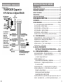
REQUIRED TOOLS ....................................................................... 5
INSTALLATION CHECK LIST ........................................................ 5
TECHNICAL ASSISTANCE ............................................................ 6
BEFORE YOU BEGIN .................................................................... 6
PRECAUTIONS ......................................................................... 7-8
USING YOUR TEST PROBE .......................................................... 8
MAKING WIRING CONNECTIONS ........................................... 8-10
COMPONENTS ........................................................................... 11
WIRING DIAGRAMS ............................................................. 11-12
H1 – 6-PIN HEAVY GAUGE WIRING CONNECTIONS ................. 13-14
H1/1 Violet Wire – Starter Output .............................................. 13
H1/2-3 Red Wire - +12V Power Input ......................................... 14
H1/4 Yellow Wire – Ignition 1 Output.......................................... 14
H1/5 Pink Wire – Ignition 2 Output ............................................ 14
H1/6 Brown Wire – Accessory Output (Heater/ACC Output) ........... 14
H2 – 5 PIN WIRE HARNESS ...................................................... 15
H2/1 Red/White Wire – Parking Light Relay Power Input ............... 15
H2/2 White Wire – Parking Light Relay Output ............................. 15
H2/3 Black Wire – System Ground ............................................. 15
H2/4 Brown Wire – (-) 200 ma Horn Output ................................ 15
H2/5 Red Wire – System Power ................................................. 15
H3 –BLACK 4-PIN CONNECTOR
FOR TWO-WAY TRANSCEIVER/ANTENNA MODULE ....... 15-16
H4 – 9-PIN BLACK WIRE HARNESS ...................................... 16-20
H4/1 Violet/White Wire – Tach Input Connection .......................... 16
H4/2 Thin Black Wire – (-) Neutral Safety Switch or ..................... 17
(-) Remote Toggle Switch Input
H4/3 Brown/Red wire – (+)
Positive Safety Shut Down Brake or Handbrake ........................ 17
H4/4 Grey wire – (-) Negative Safety Shut Down ......................... 17
For Hood Pin Switch
H4/5 Red/White Wire – (-) 200mA Channel 3 Trunk Output ........... 18
H4/6 Brown/Black Wire – (-) 200mA Factory Security Rearm
Signal/ Key Sensor Output .................................................... 18
Factory Security Rearm Signal Output
Ground Output During Start (Crank)
H4/7 Black/White Wire–(-)200mA Dome Light Supervision Output . 19
H4/8 Lt. Green/Black Wire – (-) 200mA Programmable Output ...... 20
INSTALLATION TABLE OF CONTENTS

614
TRANSPONDER / PASSLOCK III
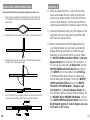
Note: If the vehicle does not start with the Remote
Starter or runs for approx 5 seconds and shuts
down, try adjusting or changing the position of the
Transponder Key in the Bypass Module or adjusting
the position of the (2)Two Loop Antenna wire around
the Transponder Pick-up/Receiver Antenna as men-
tioned above.
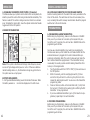
When connecting the Anti-Theft Bypass Module to
your Remote Starter, you will need to activate this
Bypass Module by connecting it in different ways
depending on the Remote Starter you have. Attach
the WHITE/GREEN (-)Security Bypass Output
wire from the 8-Pin Harness to: if the unit you are
using has a 4-Relay Pack, tap this WHITE/GREEN
wire into the Thin WHITE wire in the middle of the
3-Pin Plug, if the Remote Start does not have a
4-Relay Pack and the Relays are On-Board, connect
the WHITE/GREEN wire to the WHITE, YELLOW
or YELLOW BLACK (-)Negative Ignition Output
or (-) Security Bypass Output wire from the Main
Harness on these Remote Starters. On the DELUXE
200 or DELUXE 500 Models, connect this GREEN/
WHITE wire to the BLUE/BLACK Ignition 3 Con-
trol Output wire, the H4/9 wire or H7/1 wire.
5.
6.
Dual Pulse Door Unlock Output
Factory Security Disarm Signal Output
Start Status (By-pass Control) Output
H4/9 Blue/Black Wire – (-) 200mA Security Bypass Output ........... 20
GM VATS Key Override
H5 6-PIN DOOR LOCK CONNECTIONS .................................. 21-22
H6 2-PIN BLUE CONNECTOR FOR THE PROGRAM SWITCH ........ 19
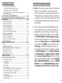
PROGRAMMING ................................................................... 23-30
Programming Transmitter ......................................................... 23
Feature I Programming ........................................................ 23-24
Feature II Programming ........................................................... 25
Feature III Programming .......................................................... 26
Feature IV Programming ........................................................... 27
Engine Checking Tach/RPM Learning ...................................... 27-28
Check Level Programming ......................................................... 28
Engine Checking Voltage ........................................................... 28
Start Timer Programming ......................................................... 29
Return to Factory Default Setting .......................................... 29-30
Shutdown Diagnostics .............................................................. 30
TESTING YOUR INSTALLATION ........................................... 31-35
Caution .................................................................................. 31
Neutral Start Safety Test .......................................................... 31
Mechanical Neutral Safety Switch Considerations ......................... 32
Park/Neutral ECM Input ....................................................... 32-33
Key In Sensor Circuits .............................................................. 33
Maintaining Factory Circuits ................................................. 33-35
OWNER’S WARNING ................................................................. 36
REMOTE TRANSMITTER OPERATION .......................................... 37-39
A. Transmitter Functions .......................................................... 37
B. Lock Doors ........................................................................ 37
C. Unlock Doors ..................................................................... 37
D. Car Locator ........................................................................ 38
E. Panic Function .................................................................... 38
F. Dome Light Convenience Delay and Supervision ...................... 38
G. Ignition Controlled Door Lock and Unlock ............................... 38
H. Trunk Release (Channel 3) Output......................................... 38
I. Driver Paging ...................................................................... 38
J. Vibration/Melody Mode ......................................................... 39
K. Screen Lamp On .................................................................. 39
TABLE OF CONTENTS

560
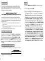
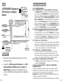
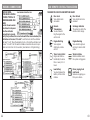
routed through the Steering Column and up towards
and then around the Ignition Key Cylinder and
needs to be positioned so that there are at least
(2)Two turns (the more turns the better chance
the signal will be Received by the Factory Receiver
Antenna) around the Ignition Key Cylinder as shown
below.
Transponder systems often have a BLACK PLAS-
TIC RING around the Ignition Lock Switch. This is
the vehicle’s Transponder Pick-up or Receiver Ring
Antenna. It is important that the at Least (2) Two
loops of the Bypass Module’s TRANSPONDER
LOOP ANTENNA be mounted on or as close to
the Factory Receiver Ring (BLACK PLASTIC RING)
as possible. Slide the tube up towards the ignition
switch to tighten up the loops of wire. Tape in place
to hold. Plug the 2-Pin Connector of the Transponder
Loop Antenna into the Universal Bypass Module.
TRANSPONDER / PASSLOCK III
Now start the vehicle with the Remote Starter. If
the vehicle starts and runs for at least 30 seconds
the Transponder Bypass Module, the placement of
the Key inside the Bypass Module and the Tran-
sponder Loop Antenna are installed correct.
4.
TABLE OF CONTENTS
REMOTE START OPERATION ................................................ 39-42
A. To Remote Start Your Vehicle ........................................... 39-42
B. To Operate Your Vehicle While Running on the Remote Start ..... 40
C. Pit Stop Feature .................................................................. 40
D. Timer Start ................................................................... 40-41
E. To Turn Off the Remote Starter ............................................. 41
F. Shut Down Input for Remote Starter ...................................... 41
G. Disabling the Remote Start System ....................................... 42
LCD REMOTE TRANCEIVER ........................................................ 43
REMOTE LCD ICON DESCRIPTIONS ........................................... 43
MODEL IF114 SECURITY BYPASS MODULE .......................... 44-54
WARRANTY............................................................................... 55
REQUIRED TOOLS
Unless your remote starter includes a Bonus Installation Kit you will need
the following items: a sharp knife, electrical tape and a computer-friendly
test light. A 5/16-inch drill bit may be needed to install the hood pin switch.
If the bottom of your dash on the driver’s side will come off, you must
remove it. If this is the case a screwdriver or a wrench may be needed.
INSTALLATION CHECK LIST
• Read the manual.
• Watch the video.
• Verify that you have all the parts listed in the manual.
• Obtain the correct wiring chart for you vehicle.
• Identify air bag and SRS wires before starting your installation.
Check to see if additional parts are needed. These items are identied in
your manual and the wiring chart diagram for your vehicle.
Possible items to review:
• Anti-theft By-pass included • Relays • Diodes
• Transponder Key • EZ-Bus • Resistors
Check for optional parts to make your installation easier:
• T-harness • EZ-Bus

6
TRANSPONDER / PASSLOCK III
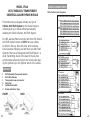
purchase one through JBS Technologies, but make sure
they program all keys to the vehicle since learning just
one transponder could erase all other key transponders
(including the key used for the Bypass Module).
Again, an extra Programmed Transponder
Ignition Key that starts the vehicle, will need to
be placed inside the Anti-Theft Bypass Module.
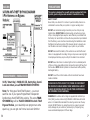
Pull apart the case and place the Programmed
TRANSPONDER KEY, inside the 10-Wire Loop on
the circuit board. Transponder Keys are directional
and must be placed along the same direction that
the key would lay in the Ignition Switch. Use the
double stick foam tape provided, one layer on the
circuit board and then the Transponder Key, and
nally the second double-stick foam tape layer on
top of it to hold key securely in place, See Below:
The TRANSPONDER LOOP Antenna must be
1.
2.
3.
TECHNICAL ASSISTANCE
Should you need help. First check our website at www.bulldogse-
curity.com or call our toll-free Tech Support Hotline at:
800-878-8007.
BEFORE YOU BEGIN
If your vehicle has an anti-theft system, you will need an addi-
tional module, Part #791.
Congratulations, you have purchased one of the most advanced remote
starter systems ever made. Your new remote starter is a technological
breakthrough utilizing the most advanced, state of the art technology
and components. The dependability and variety of features make Bulldog
Security the leader in the industry. Enjoy your new remote starter for
years to come!
This remote system is designed to start your vehicle by sending a com-
mand signal from the remote transmitter. It is important that your instal-
lation be done in a well-ventilated area. It is the responsibility of the
owner to ensure that the remote system is not used to start the
vehicle in an undesired location.
It is recommended that a carbon monoxide detector be installed in
the living area near a location where the vehicle may be garaged.
Since there are many different makes and models of vehicles,
visit our website, www.bulldogsecurity.com.
Read this manual thoroughly before starting the installation.
TACH/TACHLESS OPERATION
In most cases the decision to go with tachless mode will save time during
the installation. If your vehicle is hard-starting then you should use tach
mode.
MAKE SURE YOU PLACE THE WARNING STICKER UNDER YOUR HOOD.
59

7
SATURN
TRANSPONDER / PASSLOCK III
VATS, ‘Smart Key’, PASSLOCK III, Sentry Key, Securi-
Lock and others, are all TRANSPONDER SYSTEMS:
Note: For this type of Anti-Theft System – you must
sacrice one of your spare Programmed Transponder
Ignition Keys that STARTS this vehicle. This extra TRAN-
SPONDER Key will be PLACED INSIDE the Anti-Theft
Bypass Module, your dealership can program an extra
spare key, you can get one from a local Lock Smith or
758
PRECAUTIONS
This system is designed for use with vehicles equipped with fuel-
injected, gasoline engines and automatic transmissions only.
SAFETY FIRST!
Never start your vehicle if it is indoors. A periodic safety check is rec-
ommended to ensure that your system is in proper working order.
DO NOT use mechanical wiring connections, such as crimp or snap
together taps. DO NOT USE mechanical wiring connections such as a
crimp or snap together taps except on wires that are pre-installed from
the factory. For wires that do not have the snap connectors pre-installed
from the factory, wires must be connected using the illustrations under
the Making Connections section of this manual. Failure to properly con-
nect the wires can result in damage to your system or your vehicle.
DO NOT disconnect the battery if the vehicle has an anti-theft-coded
radio or is equipped with an airbag. Doing so may cause a warning light
to be displayed and may require a trip to the dealer to be corrected.
DO NOT leave the interior or exterior lights on for an extended period
of time as it may cause battery drain. Remove the dome light fuse from
the fuse box. NOTE: Starter systems do not work well with a partially
discharged battery.
DO NOT mount the control module until all connections have been
made and tested.
PLEASE USE CAUTION: DO NOT CUT, PROBE OR DISCONNECT
THE VEHICLE’S AIRBAG WIRES. THESE WIRES WILL ALMOST
ALWAYS BE INSIDE A BRIGHT YELLOW TUBE LOCATED NEAR
THE STEERING COLUMN HARNESS.
WARNING! On vehicles with air bags or supplemental restraint sys-
tems (SRS) you may notice a bright YELLOW or RED tube with small
wires in it marked SRS underneath the steering column near the key
cylinder. DO NOT tamper or unplug these for any reason to prevent
costly damages to your vehicle or personal injury. Tampering may
cause unintended deployment of the air bags.

578
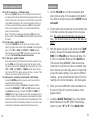
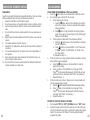
Cut the PINK wire in half and connect as shown.
Turn all Dip Switches OFF.
When connecting the Anti-Theft Bypass Module to
your Remote Starter, you will need to activate this
Bypass Module by connecting it in different ways
depending on the Remote Starter you have. Attach
the WHITE/GREEN (-)Security Bypass Output
wire from the 8-Pin Harness to: if the unit you are
using has a 4-Relay Pack, tap this WHITE/GREEN
wire into the Thin WHITE wire in the middle of the
3-Pin Plug, if the Remote Start does not have a
4-Relay Pack and the Relays are On-Board, connect
the WHITE/GREEN wire to the WHITE, YELLOW
or YELLOW BLACK (-)Negative Ignition Output
or (-) Security Bypass Output wire from the Main
Harness on these Remote Starters. On the DELUXE
200 or DELUXE 500 Models, connect this GREEN/
WHITE wire to the BLUE/BLACK Ignition 3 Con-
trol Output wire, the H4/9 wire or H7/1 wire.
2.
3.
4.
SATURNPRECAUTIONS
If your vehicle is equipped with air bags or a supplemental restraint
systems (SRS) and you CAN NOT identify the air bag wires, STOP THE
INSTALLATION IMMEDIATELY and have a professional identify the air bag
wires before continuing the installation.
WARNING! GENERAL MOTORS
REAR WHEEL DRIVE VEHICLES AND DODGE DAKOTAS
All General Motors rear wheel drive vehicles and Dodge Dakotas built
prior to 1996 do not have an electrical Neutral Safety switch. They have
a mechanical neutral safety switch. The mechanical neutral safety switch
operates as follows.
a) The key will only turn to start position when the gear selector is in
park or neutral.
b) The key can only be removed from the ignition switch when the gear
selector is in the park position.
You must use special precautions with this system.
USING YOUR TEST PROBE
To operate your test probe, connect the BLACK clip to a good chassis
ground. Then connect the RED clip to a good 12V (+) positive source.
If the test probe is connected correctly, both the GREEN and the RED
lights will be dimly illuminated. If a (+) positive source is probed, the
RED light will glow bright and the GREEN light will go out. If a (-) nega-
tive source is probed, the GREEN light will glow bright and the RED light
will go out.
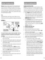
MAKING WIRING CONNECTIONS
Strip back two inches of insulation on the wire from the remote starter.
1.

PASSLOCK II
9
SATURN
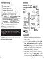
Saturn vehicles (1996-2000) with Factory Keyless
Entry have a unique Anti-Theft System.
Locate the Factory Alarm Module located behind
the Right Rear Quarter Panel (trunk area). Connect
the PINK and YELLOW/BLACK wires of Connector “J
and D” of the Factory Anti-Theft Module as shown.
1.
56
Strip back one inch of insulation on the wire you need to connect to.
Separate the vehicle wire(s) as shown. Make the separation large
enough to t the other wire through.
Insert the wire(s) from the starter through the hole as shown. If
two or more wires are inserted, wrap them in opposite directions.
Wrap the wire around one side then the other and nally around
itself as shown.
Use electrical tape to wrap. Be sure to cover the wire about two
inches on either side of the connection. First pull the wire that you
have just connected along side the wire you connected to, tape
and wire tie them together. Use this method for all connections.
CAUTION: All wires must be wrapped with tape and wire tied.
1.
2.
3.
4.
5.
MAKING WIRING CONNECTIONS

10
With the probes held rmly – dial-in the nal resis-
tance value needed for your system by turning the
screw on the variable resistor on the side of the unit
next to the Dip Switches. Turn the screw until the re-
sistance value matches the resistance value of the key.
Connect the bypass module using the diagram on the
next page. Be sure to tape up any connections DO
NOT leave any exposed wires.
When connecting the Anti-Theft Bypass Module to
your Remote Starter, you will need to activate this
Bypass Module by connecting it in different ways
depending on the Remote Starter you have. Attach
the WHITE/GREEN and GRAY/BLACK (-)Security
Bypass Output wires from the 8-Pin Harness to: if
the unit you are using has a 4-Relay Pack, tap this
WHITE/GREEN and GRAY/BLACK wires into the
Thin WHITE wire in the middle of the 3-Pin Plug,
if the Remote Start does not have a 4-Relay Pack
and the Relays are On-Board, connect the WHITE/
GREEN and GRAY/BLACK wires to the WHITE,
YELLOW or YELLOW BLACK (-)Negative Igni-
tion Output or (-) Security Bypass Output wire
from the Main Harness on these Remote Starters. On
the DELUXE 200 or DELUXE 500 Models, connect
this GREEN/WHITE and GRAY/BLACK wires to the
BLUE/BLACK Ignition 3 Control Output wire, the
H4/9 wire or H7/1 wire.
8.
9.
10.
PASSLOCK II
5510
MAKING END TO END CONNECTIONS
Use this method ONLY when connecting two separate wires end to end.
When tying two separate wires together at their ends, strip back
1” of insulation on both wires and separate the strands of wire as
shown below.
Strip back one inch of insulation on the wire you need to connect to.
Separate the vehicle wire(s) as shown. Make the separation large
enough to t the other wire through.
Insert the wire(s) from the starter through the hole as shown. If two
or more wires are inserted, wrap them in opposite directions.
1.
2.
3.
4.

1154
Turn the key to the “Run” position and place the
vehicle in Reverse.
Turn the key to start, then release the key to the
“run” position and measure the resistance between
the KEY SIDE of the YELLOW wire (this wire will
show 1 to 6 V DC on a Volt/Ohm Meter) and the
ORANGE/BLACK wire or BLACK wire (this wire
will show GROUND) the RED/WHITE wire is NOT
USED!!. (The vehicle will not start since you are not
in Park but be sure to have your foot on the brake
for safety.) Reverse your test leads around, to verify
that you get the same readings. If you get two dif-
ferent readings – we have found that the higher
of the two readings is the correct resistance – but
check again.
When you have identied the correct resistance use
the chart on Page 47 to set the resistance on the
bypass module. Locate the closest value that is less
than your desired value. Set Dip-Switches 2 through
6 to match the chart on Page 47.
Put your ohm meter (multi-meter) probes on the
(2)Two silver resistance measuring pads through the
opening shown in the drawing – making good con-
tact with these (2)Two silver pads on the board. (See
drawing on page 44). Or put your (2)Two probes into
the (2)Two holes on the bottom of the case making
contact with the underside of the silver pads. Either
contact point method will work.
4.
5.
6.
7.
PASSLOCK II COMPONENTS
• 1 - Main Control Model • 1 - 9-Pin harness
• 1 - 4-button 2-way LCD • 1 - 4-Pin Antenna Harness
Remote Transmitters • 1 - 6-Pin Door Lock Harness
• 1 - Antenna • 1 - Installation Kit
• 1 - Pin Switch • 1 - Installation & Owner’s Manual
• 1 - 6-Pin Harness • 1 - Instructional DVD
• 1 - 5-Pin Harness • 1 - IF 114 Anti-Theft Bypass Module
• 1 - 8-Pin Harness
WIRING DIAGRAM

5312
PASSLOCK I
PASSLOCK II
Remove the Lower Steering Column cover on the
Steering Column.
Locate the (3)Three Small 20 Gauge wires (YEL-
LOW, ORANGE/BLACK sometimes BLACK and
RED/WHITE wires) coming out of the Ignition Key
Cylinder of the Steering Column, these wires are
usually wrapped in BLACK friction tape.
Cut the Yellow wire in half and strip back both ends.
Remove the insulation on the Orange/Black wire with-
out cutting the wire. The Red/White wire is not used.
1.
2.
3.
WIRING HARNESSES
Keep all wiring away from moving engine parts, exhaust pipes and high
tension cable. Tape wires that pass through holes on the rewall to
prevent fraying. Watch out for sharp edges that may damage wires and
cause short circuits.
CAUTION: Do not connect the wire harness to the control module
until all wiring to vehicle is complete.

1352
connector (between the Heavy Gauge RED and
RED/WHITE wires), in the main Ignition Switch
Harness. NOTE ** This is a different wire than the
BLACK GROUND wire mentioned in the above
steps.
Connect the Bypass module using the diagram be-
low. Be sure to tape up any connections, DO NOT
leave any exposed wires.
When connecting the Anti-Theft Bypass Module to
your Remote Starter, you will need to activate this
Bypass Module by connecting it in different ways
depending on the Remote Starter you have. Attach
the WHITE/GREEN (-)Security Bypass Output
wire from the 8-Pin Harness to: if the unit you are
using has a 4-Relay Pack, tap this WHITE/GREEN
wire into the thin WHITE wire in the middle of the
3-Pin Plug, if the Remote Start does not have a
4-Relay Pack and the Relays are On-Board, connect
the WHITE/GREEN wire to the WHITE, YELLOW
or YELLOW BLACK (-)Negative Ignition Output
or (-) Security Bypass Output wire from the Main
Harness on these Remote Starters. On the DELUXE
200 or DELUXE 500 Models, connect this GREEN/
WHITE wire to the BLUE/BLACK Ignition 3 Con-
trol Output wire, the H4/9 wire or H7/1 wire.
8.
9.
PASSLOCK I WIRING CONNECTIONS
H1: 6-PIN HEAVY GAUGE WIRING CONNECTIONS:
Remember that the system duplicates the functions of the ignition key
switch! Below, we will explain the three basic functions of the ignition
switch. Since this installation will require analysis of the ignition switch
functions, we recommend making the three connections below at the
ignition switch harness directly.
H 1 / 1 - Violet wire - Starter Output
Careful consideration for the connection of this wire must be made
to prevent the vehicle from starting while in gear. The connection
of the VIOLET wire will be made to the low current start solenoid
wire of the ignition switch harness. This wire has +12 volts (red
LED on the test light) when the ignition switch is turned to the
“START” (CRANK) position only. This wire will not show +12
volts in all other ignition switch positions. NOTE: This wire must
be connected to the vehicle side of the starter cut relay (when
used). For the electrical neutral switch conguration, this connec-
tion must be made between the starter inhibit relay (when used)
and the neutral safety switch as shown in the following diagram.
Failure to connect this wire to the ignition switch side of the
neutral safety switch can result in personal injury and property
damage. SEE NEUTRAL START SAFETY TEST FOR FURTHER
DETAILS.

51
14
PASSLOCK I
Cut the YELLOW wire in half and strip back both
ends. Remove some of the insulation on the BLACK
wire without cutting the wire and the WHITE wire is
not used!!.
Put the vehicle into reverse then turn the ignition key
to the Start position and release it to the run posi-
tion. The vehicle will not start since you are not in
Park – but be sure to have your foot on the brake for
safety.
With the ignition key still in and turned to the “RUN”
position, measure the resistance between the KEY
SIDE of the YELLOW wire (this wire will show 1 to
6 V DC on a Volt/Ohm Meter) and the BLACK wire
(this wire will show GROUND). Make several mea-
surements to verify that you have a consistent resis-
tance. Reverse your test leads around, to verify that
you get the same readings. If you get two different
readings – we have found that the higher of the two
readings is the correct resistance – but check again.
When you have identied the correct resistance use
the chart on Page 47 to set the resistance on the
bypass module.
Locate the BLACK “Bulb Test” wire in the Ignition
Switch Harness on the LEFT SIDE of the Steering
Column in cavity “D” or “E” of the Black 5-Pin
3.
4.
5.
6.
7.
WIRING CONNECTIONS
H1/2, H1/3 - Red wires - +12V Power Input -
Remove the (2) 20A fuses prior to connecting these wires and do
not replace them until the satellite has been plugged into the control
module. These wires are the source of current for all the circuits the
relay satellite will energize. They must be connected to a high cur-
rent source. Since the factory supplies (+) 12V to the key switch
that is used to operate the motor, it is recommended that these
wires be connected there.
Note: I f the factory supplies two separate (+) 12V feeds to the
ignition switch, connect one RED wire of the satellite to each feed at
the switch.
H1/4 -Yellow wire - Ignition Output -
Connect the YELLOW wire to the ignition wire from the ignition
switch. The ignition wire should receive “12 volts” when the ignition
key is in the “ON” or “RUN” and “START” or “CRANK” position.
When the ignition is turned “OFF”, the ignition wire will not show
+12 volts. The YELLOW wire must be connected.
H1/5 - Pink wire - Ignition 2 Output
Some vehicles have (2) ignition wires that must be connected. Con-
nect the PINK wire to the ignition 2 wire from the ignition switch.
The ignition wire will show “12 volts” when the ignition key is in the
“ON” or “RUN” and “START” or “CRANK” position. When the igni-
tion is turned “OFF”, the ignition wire will not show +12 volts. If the
PINK wire is not used, cap the end of the wire.
H1/6 Brown wire - Accessory Output (Heater /ACC Output) –
Connect the BROWN wire to the accessory wire in the vehicle that
cowers the climate control system.
An accessory wire will show + 12 volts when the ignition switch is
turned to the “ACCESSORY” or “ON” and “RUN” positions, and will
show 0 Volts when the key is turned to the “OFF” and “START” or
“CRANK” position. There will often be more than one accessory wire in
the ignition harness. The correct accessory wire will power the vehicle’s
climate control system. Some vehicles may have separate wires for the
blower motor and the air conditioning compressor. In such cases, it will
be necessary to add a relay to power the second accessory wire.

1550
VATS
PASSLOCK I
Remove the Lower Steering Column cover on the
Steering Column.
Locate the (3)Three small 20 Gauge wires (YEL-
LOW, BLACK and WHITE wires in a GRAY or
BLACK Plug) coming out of the Ignition Key Cyl-
inder on the Bottom right hand side of the Steering
Column.
1.
2.
WIRING CONNECTIONS
H2: 5-PIN WIRE HARNESS:
H2/1 – RED/WHITE wire – Parking Light Relay Power Input –
The RED/WHITE wire is the input to the ashing parking light relay.
The connection of the RED/WHITE wire will determine the Output
Polarity on the ashing parking light relay wire WHITE. If the vehicle
you are working on is a (+) Positive Parking Light wire, leave the
RED and RED/WHITE wires connected together and connect these
wires to a (+) 12 Constant source. If your vehicle’s Parking Light
wire is a (-) Negative you will need to cut the RED/WHITE wire from
the RED wire, place the RED wire to a (+) 12 Constant source and
then connect the RED/WHITE wire to a good body Ground.
H2/2 - White wire - Parking Light Relay Output (10A power output)
Connect the WHITE wire to the parking light wire coming from
the headlight switch. Do not connect the WHITE wire to the dash-
board lighting dimmer switch. (Damage to the dimmer will result).
The limitation of the WHITE wire is 10 AMP max. Do not exceed
this limit or damage to the alarm and parking relay will result.
H2/3 - Black wire - System Ground -
This is the main ground connection of the alarm module. Make this
connection to a solid section of the vehicle frame. Do not connect
this wire to any existing ground wires sup lied by the factory wire
loom, make the connection to the vehicle’s frame directly.
H2/4 - Brown wire - (-1 200mA Horn Output -
This wire is provided to use the existing vehicle’s horn as the
keyless entry system’s optional’s warning audible device. It’s a
transistorized low current output, and should only be connected to
the low current ground output from the vehicle’s horn switch.
H2/5 - Red wire - System Power (+12V Constant) -
The RED wire supplies power to the system. Connect this wire to
a constant +12 volt source.
H3: BLACK 4-PIN CONNECTOR. - TWO-WAY TRANSCEIVER/
ANTENNA MODULE
The Two-way transceiver/antenna mounts on the location above the
dashboard of the vehicle for best reception. We suggest you mount it
on the lower left or upper left-hand side of windshield.
Warning! Do not mount in such a manner that it obstructs the driver’s view.
- Remove the protective tape backing.
- Carefully align the two-way transceiver/antenna and apply to windshield.

4916
VATS
WHITE or (1) WHITE/BLACK striped and
(1)PURPLE/BLACK striped) 20 Gauge wires,
these wires are often in a ORANGE or BLACK Plas-
tic Tube. Be careful not to cut into the YELLOW
Air Bag wires! The Air Bag wires are often in a
YELLOW Plastic Tube that is clearly marked. The
VATS wires run from the Ignition Switch down
the Steering Column to the under side of the
dash. Connect the Universal Bypass Module using
the diagram on the next page.
When connecting the Anti-Theft Bypass Module to
your Remote Starter, you will need to activate this
Bypass Module by connecting it in different ways
depending on the Remote Starter you have. Attach
the WHITE/GREEN (-)Security Bypass Output
wire from the 8-Pin Harness to: if the unit you are
using has a 4-Relay Pack, tap this WHITE/GREEN
wire into the Thin WHITE wire in the middle of the
3-Pin Plug, if the Remote Start does not have a
4-Relay Pack and the Relays are On-Board, connect
the WHITE/GREEN wire to the WHITE, YELLOW
or YELLOW BLACK (-)Negative Ignition Output
or (-) Security Bypass Output wire from the Main
Harness on these Remote Starters. On the DELUXE
200 or DELUXE 500 Models, connect this GREEN/
WHITE wire to the BLUE/BLACK Ignition 3 Con-
trol Output wire, the H4/9 wire or H7/1 wire.
6.
WIRING CONNECTIONS
- Route the black connector wire behind the trim and connect to the
two-way transceiver/antenna.
- Connect the other end to the control module.
- Special considerations must be made for windshield glass as some
newer vehicles utilize a metallic shielded window glass that will
inhibit or restrict RF reception. In these vehicles, route the two-way
transceiver/antenna module away from metallic shielded window
glass as far as possible.
H4: 9-PIN WIRE CONNECTORS:
H4/1 - Violet / White wire - Tach. Input Connection -
Note: You should connect this wire if you program the Feature IV – 2 to
“Engine Checking TACH” otherwise do not connect this wire and tape the
end. Note: No connection of this wire is required, if you use the
voltage checking type mode.
This input provides the remote start system with information about the
engines revolutions per minute (RPM). It can be connected to the nega-
tive side of the coil in vehicle with conventional coils. In multi-coil and
high energy ignition system locating a proper signal may be more dif-
cult. Once connected, test the tachometer wire, a multi-meter capable
of testing AC voltage must be used. The tach wire will show between 1V
and 6V AC at idle, and will increase as engine RPM increases. In multi-
coil ignition system, the system can learn an individual coil wire. Indi-
vidual coil wires in a multi-coil ignition system will register lower amounts
of AC voltage. Also, if necessary, the system can use a fuel injector
control wire for engine speed sensing. Common locations for a tach wire
are the ignition coils itself, the back of the gauges, engine computers,
and automatic transmission computers.
IMPORTANT! Do not test tach wires with a test light or logic probe.
The vehicle will be damaged.
How to nd a tach wire with your multi-meter:
1. Set the ACV or AC voltage (12V or 20V is ne.)
2. Attach the (-) probe of the meter to chassis ground.
3. Start and run the vehicle.
4. Probe the wire you suspect of being the tach wire with the red probe of the meter.
5. I f this is the correct wire the meter will read between IV and 6V.
IMPORTANT NOTE: You must o. ro-a ram the “Tach Signal” before
trying to remote start.

1748
VATS
Measure the resistance of the little Pellet on the
Ignition Key. It should be between 392 Ohms and
11,800 Ohms. To do this, put the Ohm Meter probes
on each side of the Key Pellet. The Resistance value
should be close to one of the following (all values in
Ohms): 392, 523, 681, 887, 1.13K, 1.87K, 3.01K,
3.74K, 4.75K, 6.04K, 7.50K, 9.53K, 11.8K.
Locate the closest value that is less than your
desired value. Set Dip Switches 2 through 6 to
match the chart on Page 47.
Put your Ohm Meter (multi-meter) probes on
the (2)Two Silver Resistance Measuring Pads
through the opening shown in the drawing – mak-
ing good contact with these (2)Two Silver Resistance
Measuring Pads on the board. (See drawing on page
1). Or put your (2)Two Ohm Meter (multi-meter)
probes into the (2)Two holes on the bottom of the
case making contact with the underside of the Silver
Pads. Either contact point method will work.
With the probes held rmly – dial-in the nal resis-
tance value needed for your system by turning the
screw on the variable resistor on the side of the unit
next to the Dip Switches. Turn the screw unit the
resistance value matches the resistance value of the
Pellet on the Key.
Locate the pair of VATS wires sometimes (2)
1.
2.
3.
4.
5.
WIRING CONNECTIONS
H4/2 - Thin Black wire - (-) Neutral Safety Switch or (-)
Remote Toggle Switch Input -
When the THIN BLACK wire is grounded, the remote start unit is oper-
able. When this wire is open from ground, the remote start is disabled.
The optional “remote start toggle switch” can be added on to
temporarily disable the Remote Start Device, it can prevent
the vehicle from being remote started accidentally. This fea-
ture is useful if the vehicle is being serviced or stored in an
enclosed area. To disable the remote start, move the remote
start enable toggle switch to the ‘OFF” position. To enable the
remote start, move the optional remote start enable toggle
switch to the “ON” position.
If needed, this wire will connect to the PARK/NEUTRAL switch
in the vehicle. (See the TESTING YOUR INSTALLATION GUIDE)
IMPORTANT NOTE: Directly connect the THIN BLACK wire to the
‘GROUND” when this wire is not used.
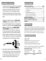
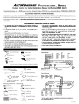
H4/3 - Brown / Red wire - (+) Positive Safety Shut Down For Brake
This wire ~provides an instant shutdown
for the remote start, whenever it receives
+12 volts. If the brake lights switch in the
vehicle switches +12 volts to the brake
light connect this wire to the output side
of the brake switch. This will allow the
remote start to shut down if an attempt is
made to operate the vehicle without the key while running under the
control of the remote start. In most vehicles, in order to shift gear, the
brake pedal must be pressed. The brake input will in turn cause the
remote start unit to shut off. (See diagram.)
H4/4 - Grey wire - (-) Negative Safety Shut Down For Hood Pin
Switch
This wire provides an instant shutdown for the remote start, when-
ever it is grounded. Connect the wire to the hood pin switch previ-
ously installed. This wire must be routed through a grommet in the
rewall and connected to the hood pin switch.
1.
2.

4718
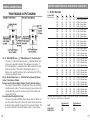
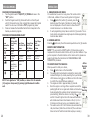
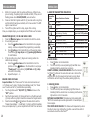
USE THIS CHART FOR VATS, PASSLOCK I & PASSLOCK II
1 - 8-Pin Harness
Dip Switch # 2 3 4 5 6
Resistor Value 0.825 1.65 3.32 6.65 13.3 Final Resistance (k ohms)
ON ON ON ON ON 0.000 +Trimpot Value
OFF ON ON ON ON 0.825 +Trimpot Value
ON OFF ON ON ON 1.650 +Trimpot Value
OFF OFF ON ON ON 2.475 +Trimpot Value
ON ON OFF ON ON 3.320 +Trimpot Value
OFF ON OFF ON ON 4.145 +Trimpot Value
ON OFF ON ON ON 4.970 +Trimpot Value
OFF OFF OFF ON ON 5.795 +Trimpot Value
ON ON ON OFF ON 6.650 +Trimpot Value
OFF ON ON OFF ON 7.475 +Trimpot Value
ON OFF ON OFF ON 8.300 +Trimpot Value
OFF OFF ON OFF ON 9.125 +Trimpot Value
ON ON OFF OFF ON 9.970 +Trimpot Value
OFF ON OFF OFF ON 10.795 +Trimpot Value
ON OFF OFF OFF ON 11.620 +Trimpot Value
OFF OFF OFF OFF ON 12.445 +Trimpot Value
ON ON ON ON OFF 13.300 +Trimpot Value
OFF ON ON ON OFF 14.125 +Trimpot Value
ON OFF ON ON OFF 14.950 +Trimpot Value
OFF OFF ON ON OFF 15.775 +Trimpot Value
ON ON OFF ON OFF 16.620 +Trimpot Value
OFF ON OFF ON OFF 17.445 +Trimpot Value
ON OFF OFF ON OFF 18.270 +Trimpot Value
OFF OFF OFF ON OFF 19.095 +Trimpot Value
ON ON ON OFF OFF 19.950 +Trimpot Value
OFF ON ON OFF OFF 20.775 +Trimpot Value
ON OFF ON OFF OFF 21.600 +Trimpot Value
OFF OFF ON OFF OFF 22.425 +Trimpot Value
ON ON OFF OFF OFF 23.270 +Trimpot Value
OFF ON OFF OFF OFF 24.095 +Trimpot Value
ON OFF OFF OFF OFF 24.920 +Trimpot Value
OFF OFF OFF OFF OFF 25.745 +Trimpot Value
All resistor values shown are in ‘K-Ohms’ or 1,000 Ohms. Thus the 1.650 value shown in
the (3) Third row is 1,650 Ohms or 1.65K Ohms.
Dip Switch #1 Dip Switch #7
VATS OFF OFF
PASSLOCK I ON ON
PASSLOCK II OFF OFF
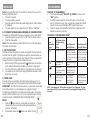
WIRING CONNECTIONS
H4/5 - RED/WHITE wire - (-) 200mA Channel 3 (Trunk) Output
This wire is a 1 Second pulsed Ground or (-) Negative Output that
can be use to operate the Electric Truck Release on a vehicle. If
the Trunk Release is a (-) Negative that is BCM controlled, no extra
parts are required. If the vehicle’s Trunk Release wire is a (+)
Positive or is not BCM Controlled, then an extra Relay Part #775 is
required. See Diagram above.
H4/6 - Brown I Black wire - (-) 2OOmA Factory Security Rearm
Signal / Key Sensor Output -
Factory Security Rearm Signal Output (Factory default setting.)
This output is programmable. If programmed it can rearm a factory
installed security system. This wire will supply a pulse whenever the
remote start times out or is shut down using the transmitter and
remote door locking.
Ground Output During Start Crank)
This wire will provide a 2OOmA ground output while the starter out-
put of the remote start unit is active. This output can be used to ac-
tivate the Crank Low/Bulb Test wire found in some GM vehicles. This
wire is also referred to as the ECM wake up wire in some vehicles.

1946
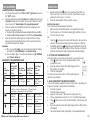
LIST OF VEHICLES AND TYPES OF SECURITY SYSTEMS
Dodge 300 M 99+ Transponder Pontiac Sunre 2000 Passlock II
Dodge Intrepid 98+ Transponder Porsche (all 97+) Transponder
Dodge Neon 2000 Transponder Saab (all 97+) Transponder
Ford Contour 97+ Transponder Saturn 97+ Factory
Ford Crown Vic 96+ Transponder Toyota Avalon 98+ Transponder
Ford Pick-UP 150/250 2000 Transponder Toyota Camry 98+ Transponder
Ford Windstar 2000 Transponder Toyota Land Cruiser 98+ Transponder
Toyota Solara 99 Transponder Toyota Supra 98+ Transponder
Volkswagon Passat 98+ Transponder Volvo (all 98+) Transponder
First determine what type of Anti-Theft System you have
in your vehicle. If unsure – follow the chart on the previ-
ous page to determine the system you have. There are
several types of systems as outlined below:
General Motors VATS, PASSLOCK I and PASSLOCK
II Anti-Theft Systems: For these, you will be required
to dial-in a resistor value that matches the resistance
on your vehicles Anti-Theft System. The method is
described on the following pages for each type of sys-
tem using the Dip Switches and the Variable/Adjustable
Resistor. The Variable Resistor is a (10)Ten turn Poten-
tiometer which can be dialed up from (0) Zero Ohms to
1,000 Ohms.
SATURN vehicles (1996-2000) simply hook up to the
Universal Bypass Module as shown on Page 57.
TRANSPONDER Anti-Theft Systems require an Extra
Programmed Ignition Key to be placed inside the Univer-
sal Bypass Module. Follow the directions on Pages 58-62.
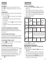
WIRING CONNECTIONS
H4/7 - BLACK/WHITE wire - (-) 200mA Dome Light Supervision
Output
This wire is a Ground Output or (-) Negative when using the Key-
less entry’s Unlock button is pressed, this wire is used to turn on
the Dome Light circuit in the vehicle. If the Dome Light circuit is
not BCM Controlled or is a (+) Positive Dome Light circuit then an
extra Relay Part #775 is required. See Diagram below.
H4/8 - LT. Green Black wire - (-) 200ma Programmable Output
Dual Pulse Door unlock Output (Factory default settings)
The dual pulse door unlock feature will work the most fully elec-
tronic door lock circuits. The vehicle must have an electronic door
lock switch (not the lock knob or key switch), which, locks and
unlocks all of vehicle’s doors. When wired for this feature, press-
ing the disarm (or unlock button one time will disarm the alarm
and unlock The drivers door only. Pressing the disarm (or unlock)
button two times within (3) seconds, will disarm the alarm and all
doors will unlock.

4520
LIST OF VEHICLES AND TYPES OF SECURITY SYSTEMS
Acura 3.2TL 98+ Transponder GMC suburban 98+ Passlock II
Acura RL 98+ Transponder GMC Sonoma 98+ Passlock II
Audi A4, A6,A8 98+ Transponder GMC Sierra 98+ Passlock II
BMW (all 97 +) Transponder GMC Safari 98+ Passlock II
Buick Century 97+ VATS GMC S-15 98+ Passlock II
Buick LeSabre 90 – 96 VATS GMC Envoy 99+ Passlock II
Buick Park Ave 91 – 96 VATS GMC Denalli 99+ Passlock II
Buick Park Ave 97+ VATS Transponder 98+ Passlock II
Buick Regal 93 – 96 + VATS Honda Accord 98+ Transponder
Buick Reviera 93 – 96 VATS Honda Odyssey 98+ Transponder
Buick Riviera 93 – 96 VATS Honda Odyssey 98+ Transponder
Buick Roadmaster 93 – 96 VATS Honda Prelude 98+ Transponder
Cadillac Allante VATS Honda Prelude 98+ Transponder
Cadillac Brougham VATS Isuzu Hombre 98+ Passlock II
Cadillac Catera 97 + VATS Jeep Grd Cheerokee 99 Transponder
Cadillac DeVille 92 - 96 VATS Jeep TJ (Wrangler) 99 Transponder
Cadillac DeVille 99 Transponder Lexus (all 97+) Transponder
Cadillac Escalade 99+ Passlock II Lincoln Continental 97+ Transponder
Cadillac Eldorado 89 - 98 VATS Lincoln Mark VIII 97+ Transponder
Cadillac Eldorado 99+ Passlock III Lincoln Navigator 97+ Transponder
Cadillac Fleetwood 90m- 96 VATS Lincoln Towncar 97+ Transponder
Cadillac Seville 90 - 98 VATS Mercedes (all 97+) Transponder
Cadillac Seville 99+ Transponder Mercury Cougar 99 Transponder
Chevrolet Venture 99+ Transponder Mercury Mystique 97+ Transponder
Chevy Astro Van 98+ Passlock II Mercury sable 96+ Transponder
Chevy Blazer 98+ Passlock II Nissan Maxima 98+ Transponder
Chevy Camaro 86+ VATS Oldmobile Instrique 98+ Transponder
Chevy Cavalier 96-99 Passlock Olds. Cutlass 97+ Transponder
Chevy Cavalier 2000 Passlock II Oldsmobile Achieva 95 Passlock I
Chevy Cavalier 88 - 89 VATS Oldsmobile Achieva 96+ Passlock II
Chevy Express 1997 Passlock II Oldsmobile Alero 99 Passlock I
Chevy Lumina 96+ VATS Oldsmobile Aurora VATS
Chevy Malibu 97+ Passlock II Oldsmobile Bravada 98 Passlock II
Chevy Monte Carlo 96 - 99 VATS Oldsmobile Eighty-Eight VATS
Chevy Pickup Full-size 98+ Passlock II Oldsmobile Ninety-Eight VATS
Chevy S-10 98+ Passlock II Oldsmobile Silhoutte 99 Transponder
Chevy Suburban 98+ Passlock II Pontiac Bonneville 89+ VATS
Chevy Tahoe 98+ Passlock II Pontiac Firebird 88+ VATS
Chevy Van 96+ Passlock II Pontiac Grand Am 96-98 Passlock
Chevy Venture 1997 + Passlock II Pontiac Grand Am 99 Passlock II
Chrysler Concorde 98+ Transponder Pontiac Grand Prix 92-96 VATS
Chrysler Sabring Conv 98+ Transponder Pontiac Montana 99 Transponder
Chrysler LHS 99 Transponder Pontiac Sunre 96 - 99 Passlock I
WIRING CONNECTIONS
Factory Security Disarm Signal Output -
This wire is designed to disarm a factory installed security system.
This wire sends a negative (-) 1 seconds pulse upon a remote
start and remote door unlocking. Some factory systems must be
disarmed to allow remote starting In most cases, this wire may be
connected directly to the factory alarm disarm wire. The correct wire
will show negative ground when the key is used to unlock the doors
or trunk. This wire is usually found in the kick panel area in the wir-
ing harness coming into the car body from the door.
Start Status Shock Sensor By-Pass Control) Output:
This wire is designed to bypass shock sensor module. This wire will
supply an output at all times the remote start is operating plus an
additional (3) seconds after the remote start unit is turned off.
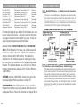
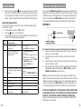
H4/9 - BLUE/BLACK wire - (-) 200mA Security Bypass Output -
This wire provides a Ground or (-) Negative Output (4) Four Sec-
onds before the Remote Start unit powers up Ignition #1. This wire
remains Grounded or (-) Negative while in Remote Start Mode. Use
this wire to activate the (-) Negative Input on a Security Bypass
Module when Bypassing the Factory Anti-theft system on a vehicle
or to Control a relay for an Ignition #3 connection if needed, See
Diagram below.
Ignition 3 output:
Some newer vehicles use a third
ignition wire which is required
to start and keep the vehicle’s
engine running. If this is the
case, wire an IGN 3 relay (not
supplied) as shown. Do not
connect any vehicle circuits
together, they are isolated for a
from Ignition reason.
On vehicles that require a factory security bypass, connect the
Blue / Black (H419) wire to the security bypass module.
Page is loading ...
Page is loading ...
Page is loading ...
Page is loading ...
Page is loading ...
Page is loading ...
Page is loading ...
Page is loading ...
Page is loading ...
Page is loading ...
Page is loading ...
Page is loading ...
-
 1
1
-
 2
2
-
 3
3
-
 4
4
-
 5
5
-
 6
6
-
 7
7
-
 8
8
-
 9
9
-
 10
10
-
 11
11
-
 12
12
-
 13
13
-
 14
14
-
 15
15
-
 16
16
-
 17
17
-
 18
18
-
 19
19
-
 20
20
-
 21
21
-
 22
22
-
 23
23
-
 24
24
-
 25
25
-
 26
26
-
 27
27
-
 28
28
-
 29
29
-
 30
30
-
 31
31
-
 32
32


Bulldog Security DELUXE 200B Owner's manual
- Category
- Security access control systems
- Type
- Owner's manual
- This manual is also suitable for
Ask a question and I''ll find the answer in the document
Finding information in a document is now easier with AI
Related papers
-
Bulldog Security GM-3 Owner's manual
-
-
-
-
-
-
-
-
-
Other documents
-
Autopage RF-1050KE Transmitter Programming
-
PAC BHA2002 User manual
-
ReadyRemote 23927 Owner's manual
-
-
-
-
-
-
 AutoCommand 20024 Installation guide
-
Directed Electronics 20402 Owner's manual
