
M9T Product Manual
SATA 2.5” Hard Disk Drive
September 04, 2013. Rev 1.0
PMM9T-SATA-100736114a

© 2013 Seagate Technology LLC. All rights reserved. Seagate and Seagate Technology are registered
trademarks of Seagate Technology LLC in the United States and/or other countries. Momentus is either a
trademark or registered trademark of Seagate Technology LLC or one of its affiliated companies in the
United States and/or other countries. All other trademarks or registered trademarks are the property of
their respective owners. When referring to drive capacity, one gigabyte, or GB, equals one billion bytes and
one terabyte, or TB, equals one trillion bytes. Your computer’s operating system may use a different
standard of measurement and report a lower capacity. In addition, some of the listed capacity is used for
formatting and other functions, and thus will not be available for data storage. Actual data rates may vary
depending on operating environment and other factors. The export or re-export of hardware or software
containing encryption may be regulated by the U.S. Department of Commerce, Bureau of Industry and
Security (for more information, visit www.bis.doc.gov), and controlled for import and use outside of the U.S.
Seagate reserves the right to change, without notice, product offerings or specifications.

Spinpoint M9T Product Manual REV 1.0
ii
TABLE OF
CONTENTS
CHAPTER 1
SCOPE .............................................................................................................................1
1.1 USER DEFINITION
..............................................................................................................................1
1.2 M
ANUAL ORGANIZATION
..................................................................................................................1
1.3 SATA
.................................................................................................................................................2
1.4 R
EFERENCE
........................................................................................................................................2
CHAPTER 2 DESCRIPTION
..............................................................................................................3
2.1 INTRODUCTION
..................................................................................................................................3
2.2 K
EY FEATURES
..................................................................................................................................4
2.3 S
TANDARDS AND
R
EGULATIONS
........................................................................................................5
2.4 H
ARDWARE
R
EQUIREMENTS
.............................................................................................................5
CHAPTER 3 SPECIFICATIONS
........................................................................................................6
3.1 SPECIFICATION SUMMARY
................................................................................................................6
3.2 P
HYSICAL SPECIFICATIONS
...............................................................................................................7
3.3 L
OGICAL
C
ONFIGURATIONS
..............................................................................................................7
3.4 P
ERFORMANCE SPECIFICATIONS
......................................................................................................8
3.5 P
OWER CONSUMPTION
......................................................................................................................9
3.6 E
NVIRONMENTAL SPECIFICATIONS
.................................................................................................10
3.7 R
ELIABILITY SPECIFICATIONS
........................................................................................................12
CHAPTER 4
INSTALLATION..........................................................................................................13
4.1 SPACE
R
EQUIREMENTS
....................................................................................................................13
4.2 U
NPACKING
I
NSTRUCTIONS
.............................................................................................................14
4.3 M
OUNTING
.......................................................................................................................................14
4.3.1
Orientation......................................................................................................................15
4.3.2 Ventilation
......................................................................................................................16
4.4 C
ABLE
C
ONNECTORS
.......................................................................................................................16
4.4.1 SATA Connectivity
..........................................................................................................17
4.5 D
RIVE
I
NSTALLATION
......................................................................................................................21
CHAPTER 5 DISK DRIVE
OPERATION........................................................................................22
5.1 HEAD / DISK ASSEMBLY (HDA)
......................................................................................................22
5.1.1 Base Casting Assembly
...................................................................................................22
5.1.2 DC Spindle Motor
Assembly...........................................................................................22
5.1.3 Disk Stack Assembly
.......................................................................................................24
5.1.4 Head Stack
Assembly ......................................................................................................24
5.1.5 Voice
Coil Motor and Actuator Latch
Assemblies ..........................................................24
5.1.6 Air Filtration
System.......................................................................................................24
5.1.7 Load/Unload
Mechanism................................................................................................24
5.2 D
RIVE ELECTRONICS
.......................................................................................................................25
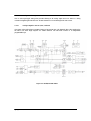
5.2.1 Digital Signal Process and Interface Controller
............................................................25
5.2.2 Disk Controller
...............................................................................................................25
5.2.2.1 The Host Interface Control Block .............................................................................................. 27
5.2.2.2 The Buffer Control Block .......................................................................................................... 27
5.2.2.3 The Disk Control Block ............................................................................................................. 28
5.2.2.4 The Disk LDPC Control Block .................................................................................................. 28
5.2.2.5 Frequency Synthesizer ............................................................................................................... 28
5.2.2.6 Power Management......
.............................................................................................................. 29
5.2.3 Read/Write
IC .................................................................................................................29
5.2.3.1 Time Base Generator.................................................................................................................. 29
5.2.3.2 Automatic Gain Control ............................................................................................................. 29
5.2.3.3 Asymmetry Correction Circuitry (ASC) .....................................................
............................... 29
5.2.3.4 Analog Anti-Aliasing Low Pass Filter ....................................................................................... 30
5.2.3.5 Analog to Digital Converter (ADC) and FIR ............................................................................. 30

Spinpoint M9T Product Manual REV 1.0
iii
5.3 SERVO SYSTEM
................................................................................................................................31
5.4 R
EAD AND WRITE OPERATIONS
......................................................................................................31
5.4.1 The Read
Channel...........................................................................................................31
5.4.2 The Write
Channel ..........................................................................................................32
5.5 F
IRMWARE FEATURES
.....................................................................................................................32
5.5.1 Read Caching
.................................................................................................................32
5.5.2 Write
Caching
.................................................................................................................33
5.5.3 Defect Management
........................................................................................................34
5.5.4 Automatic Defect Allocation
...........................................................................................34
5.5.5
SMART............................................................................................................................34
5.5.6 APM
...............................................................................................................................34
CHAPTER 6 SATA II INTERFACE
.................................................................................................35
6.1 INTRODUCTION
................................................................................................................................35
6.1.1 SATA Terminology..................................................................................................... ...35
6.2 P
HYSICAL INTERFACE
.....................................................................................................................37
6.3 S
IGNAL SUMMARY
...........................................................................................................................37
6.3.1 Signal
Descriptions.........................................................................................................37
6.3.2 I/O Register - Address
....................................................................................................38
6.3.3 Control Bl
ock Register Descriptions
..............................................................................38
6.3.3.1 Alternate Status Register (ex. 3F6h) .......................................................................................... 38
6.3.3.2 Device Control Register (ex. 3F6h)............................................................................................ 39
6.3.4 Command Block Register Descriptions
..........................................................................39
6.3.4.1 Data Register (Ex. 1F0h)............................................................................................................ 39
6.3.4.2 Features Register and Feature Extended Register (Ex. 1F1h) .................................................... 39
6.3.4.3 Sector Number Register and Sector Number Extended Register (Ex. 1F3h) .............................. 39
6.3.4.4 Error Register (Ex. 1F1h) ........................................................................................................... 39
6.3.4.5 Sector Count Register and Sector Count Extended Register (Ex. 1F2h) .................................... 40
6.3.4.6 Cylinder High Register and Cylinder High Extended Register (Ex. 1F5h) ................................ 40
6.3.4.7 Cylinde
r Low Register and Cylinder Low Extended Register (Ex. 1F4h) .................................. 40
6.3.4.8 Command Register (Ex. 1F7h)................................................................................................... 40
6.3.4.9 Device Register (Ex. 1F6h) ........................................................................................................ 40
6.3.4.10 Status Register (Ex. 1F7h) ......................................................................................................... 41
CHAPTER 7 SATA II FEATURE
SET .............................................................................................42
7.1 DEVICE ACTIVITY SIGNAL
..............................................................................................................42
7.2 S
TAGGERED SPIN-UP DISABLE CONTROL
.......................................................................................42
7.3 A
UTO-ACTIVATE IN DMA SETUP FIS
............................................................................................42
7.4 N
ATIVE COMMAND QUEUING (NCQ)
.............................................................................................42
7.5 P
HY EVENT COUNTERS
..................................................................................................................43
7.6 S
OFTWARE SETTINGS
P
RESERVATION
............................................................................................44
7.7 SATA P
OWER
M
ANAGEMENT
.........................................................................................................44
CHAPTER 8 ATA COMMAND DESCRIPTIONS
..........................................................................45
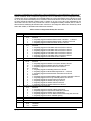
8.1 COMMAND
T
ABLE
............................................................................................................................45
8.2 C
OMMAND
D
ESCRIPTIONS
...............................................................................................................47
8.2.1 Check Power Mode
(E5h)...............................................................................................47
8.2.2 Download Micro Code
(92h)
..........................................................................................47
8.2.3 Device Configuration Overlay
(B1h)
..............................................................................47
8.2.4 Execute Device Diagnostics
(90h) ..................................................................................49
8.2.5 Flush Cache (E7h, EAh:
extended).................................................................................49
8.2.6 Format Track (50h)
........................................................................................................49
8.2.7 Identify Device (ECh)
.....................................................................................................49
8.2.8 Idle
(E3h)
........................................................................................................................55
8.2.9 Idle Immediate (E1h)
......................................................................................................55
8.2.10 Initialize Device Parameters
(91h)
.................................................................................56
8.2.11 NOP
(00h).......................................................................................................................56
8.2.12 Read Buffer
(E4h) ...........................................................................................................56
8.2.13 Read DMA (C8h,
25h:extended).....................................................................................56

Spinpoint M9T Product Manual REV 1.0
iv
8.2.14 Read FPDMA Queued
(60h)...........................................................................................56
8.2.15 Read Log Extended
(2Fh) ...............................................................................................57
8.2.16 Read Long (22h)
.............................................................................................................57
8.2.17 Read Multiple Command (C4h,
29h:extended)...............................................................57
8.2.18 Read Native Max Address (F8h, 27h :extended)
.........................................................58
8.2.19 Read Sector(s) (20h, 24h:
extended)...............................................................................58
8.2.20 Read Verify Sector(s) (40h, 41h :extended)
....................................................................58
8.2.21 Reca
librate
(10h) ............................................................................................................59
8.2.22 Security Disable Password (F6h)
...................................................................................59
8.2.23 Security Erase Prepare
(F3h)
.........................................................................................59
8.2.24 Security Erase Unit
(F4h)...............................................................................................59
8.2.25 Security Freeze Lock
(F5h).............................................................................................60
8.2.26 Security Set Password
(F1h)...........................................................................................60
8.2.27 Security Unlock
(F2h).....................................................................................................61
8.2.28 Seek (7xh)
.......................................................................................................................61
8.2.29 Set Features
(EFh)..........................................................................................................61
8.2.30 Set Max Address (F9h, 37h: extended)
...........................................................................63
8.2.31 Set Multiple Mode
(C6h).................................................................................................63
8.2.32 Sleep (E6h)
.....................................................................................................................63
8.2.33 Standby (E2h)
.................................................................................................................63
8.2.34 SMART
(B0h)..................................................................................................................64
8.2.34.1 Smart disable operations (D9h) .................................................................................................. 64
8.2.34.2 Smart enable/disable attribute auto-save (D2h).......................................................................... 64
8.2.34.3 Smart enable operations (D8h) ................................................................................................... 65
8.2.34.4 Smart execute off-line immediate (D4h) .................................................................................... 65
8.2.34.5 Smart read data (D0h) ..................................................................
.............................................. 66
8.2.34.6 SMART read log sector (D5h) ................................................................................................... 71
8.2.34.7 SMART return status (DAh) ...................................................................................................... 71
8.2.34.8 SMART write log sector (D6h) .................................................................................................. 71
8.2.35 Standby (E2h)
.................................................................................................................72
8.2.36 Standby Immediate
(E0h)................................................................................................72
8.2.37 Write Buffer (E8h)
..........................................................................................................72
8.2.38 Write DMA (CAh,
35h:extended)....................................................................................72
8.2.39 Write FPDMA Queued
(61h)
..........................................................................................72
8.2.40 Write Long
(32h).............................................................................................................73
8.2.41 Write Multiple Command (C5h, 39h:extended)
..............................................................73
8.2.42 Write Sector(s) (30h, 34h:extended)
............................................................................73
CHAPTER 9
MAINTENANCE..........................................................................................................75
9.1 GENERAL INFORMATION
.................................................................................................................75
9.2 M
AINTENANCE PRECAUTIONS
........................................................................................................75
9.3 SERVICE AND REPAIR
......................................................................................................................77

Spinpoint M9T Product Manual REV 1.0
v
TABLE OF
TABLES
Table 3-1 Specifications ............................................................................................................................6
Table 3-2 Physical Specifications ..............................................................................................................7
Table 3-3 Logical Configurations ..............................................................................................................7
Table 3-4 Performance Specifications .......................................................................................................8
Table 3-5 Power consumption ...................................................................................................................9
Table 3-6 Environmental
Specifications
...................................................................................................10
Table 3-7 Reliability Specifications.........................................................................................................12
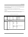
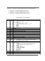
Table 4-1 SAT
A Connector Pin Definitions ............................................................................................19
Table 7-1 Phy Event Counter Supports....................................................................................................44
Table 8-1 Command Code Parameters ....................................................................................................46
Table 8-2 Device Configuration Overlay Feature Register Values..........................................................48
Table 8-3 Device Configuration Identify data structure ..........................................................................49
Table 8-4 Diagnostic
Codes
.....................................................................................................................50
Table 8-5 IDENTIFY DEVICE information ...........................................................................................51
Table 8-6
Automatic Standby Timer Periods...........................................................................................56
Table 8-7 Security password content ......................................................................................................60
Table 8-8 Security Erase Unit Password..................................................................................................61
Table 8-9 Security Set Password data content .........................................................................................61
Table 8-10 Identifier and security level bit interaction ............................................................................62
Table 8-11 Set Features Register Definitions ................................................................
..........................63
Table 8-12 Transfer Mode Values ...........................................................................................................63
Table 8-13 Set Max Feature Register Values ..........................................................................................64
Table 8-14 SMART Feature Registers Values.........................................................................................65
Table 8-15 Device SMART Data Structure .............................................................................................67
Table 8-16 SMART Attribute Status Flags..............................................................................................68
Table 8-17 SMART Attribute Data List ..................................................................................................70
Table 8-18 Off-line Data Collection Status Values .............................................
....................................70
Table 8-19 Self-test Execution Status Values ..........................................................................................71

SCOPE
Spinpoint M9T Product Manual REV 1.0
1
CHAPTER 1 SCOPE
Welcome to the Spinpoint
TM
M9T series of Samsung
TM
hard disk drive. This series of drives consists of the
following models: ST1500LM006, ST1500LM007, ST1500LM010, ST2000LM003, ST2000LM004 and
ST2000LM006. This chapter provides an overview of the contents of this manual, including the
intended user,
manual organization, terminology and conventions. In addition, it provides a list of references that might be
helpful to the reader.
1.1 User Definition
The Spinpoint M9T product manual is intended for the following readers:
Original Equipment Manufacturers (OEMs)
Distributors
1.2 Manual Organization
This manual provides information about installation, principles of operation, and interface command
implementation. It is organized into the following chapters:
Chapter 1 - SCOPE
Chapter 2 - DESCRIPTION
Chapter 3 - SPECIFICATIONS
Chapter 4 - INSTALLATION
Chapter 5 - DISK DRIVE OPERATION
Chapter 6 - SATA INTERFACE
Chapter 7 - MAINTENANCE
In addition, this manual contains a glossary of terms to help you understand important information

SCOPE
Spinpoint M9T Product Manual REV 1.0
2
1.3 SATA
The ATA (Advanced Technology Attachment) interface which was developed based on the IDE
(Integrated Drive Electronics) has been around from 1980’s. As the PC processor speed has improved,
so have the data rates of the HDD. The parallel ATA is reaching its limit of 133 MB/s data transfer rate.
Serial implementation of ATA (SATA) will allow the data rate to run even faster so the processor will
be utilized more efficiently. Serial ATA has been developed to provide the next generation storage
interface.
SATA interface replaces 2 inch wide, 40 pin parallel interface connector with 0.25 inch wide 7 pin
serial interface connector. The maximum length of the SATA interface cable can be extended to 1
meter (approximately 39 inches) compared to 18 inch of parallel ATA. SATA also allows a data
transfer speed of 150 MB/s, 300 MB/s, and 600 MB/s. Even though SATA will not directly interface
with Parallel or traditional ATA (PATA) hardware, it is compliant with ATA protocol and
therefore software compatible. The cable geometry with smaller footprint connector reduces board
space requirements and
improves air flow and heat exchange inside computer systems.
SATA uses point to point connection topology and each channel works independently. There is no
sharing of interface, master/slave drive configuration, and no master/slave jumper settings. This is
different from Parallel ATA (PATA) architecture where 2 drives per port are supported by a shared bus
and drives are designated as master or slave drive based on jumper pin or cable selection. Unlike
parallel ATA, SATA drives are hot-plug and hot-
swappable.
1.4 Reference
For additional information about the AT interface, refer to:
ATA-2 (AT Attachment 2), Revision 3, January, 1995
ATA-3 (Attachment-3 Interface) Revision 7b, 27 January, 1997
ATA-4 (AT Attachment with Packet Interface Extension) Revision 18, 19 August, 1998
ATA-5 (AT Attachment with Packet Interface Extension) Revision 3, 29 February, 2000
ATA-6 (AT Attachment with Packet Interface Extension) Revision 2a, 26 September, 2001
ATA-7 (AT Attachment with
Packet Interface Extension) Revision 1, 28 August, 2002
ATA-8 (AT Attachment with Packet Interface Extension) Revision 0, 16 September, 2008
For introduction about SATA interface please refer to:
SATA 1.0 Design Guides, April 5, 2002.
(URL: http:// www.serialdata.org retrieved on May 22, 2003)
Serial ATA: A comparison with Ultra ATA Technology
(URL:
http://www.intel.com retrieved April
18,2003)
Serial ATA II: Port Multiplier 1.0 Specification, April 29th, 2003.
(URL:
http://www.serialdata.org retrieved on May 22, 2003)
Serial ATA International Organization: Serial ATA Revision 3.1, July 18, 2011,
(URL:
http://www.serialdata.org)

Spinpoint M9T Product Manual REV 1.0
3
DESCRIPTION
CHAPTER 2 DESCRIPTION
This chapter summarizes general functions and key features of the Spinpoint M9T hard disk drive, as well as the
standards and regulations they meet.
2.1 Introduction
The Samsung Spinpoint M9T 2.5-inch hard disk drive is high capacity, high performance random access storage device,
which uses non-removable 2.5-inch disks as storage media. Each disk incorporates thin film metallic media technology
for enhanced performance and reliability. And for each disk surface there is a corresponding movable head actuator
assembly to randomly access the data tracks and write or read the user data.
The Spinpoint M9T hard disk drive includes the AT controller embedded in the disk drive PCB electronics. The drive's
electrical interface is compatible with all mandatory, optional and vendor-specific commands within the ATA
specification.
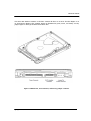
Drive size conforms to the industry standard 2.5-inch form factor with a SATA 15-pin DC power connector, and the
standard SATA 7-pin Interface connector.
The Spinpoint M9T hard disk drive incorporates TuMR head and Noise Predictive PRML (Partial Response
Maximum Likelihood) signal processing technologies. These advanced technologies allow for areal density of about 950
Gb per square inch and storage capacity of over 667 Gigabytes per disk.
The heads, disk(s), and actuator housing are environmentally sealed within an aluminum-alloy base and cover. As the
disks spin, air circulates within this base and cover, commonly referred to as the head and disk assembly (HDA), through
a non-replaceable absolute filter ensuring a contamination free environment for the heads and disks throughout the life of
the drive.

Spinpoint M9T Product Manual REV 1.0
4
DESCRIPTION
2.2 Key Features
Key features of the Spinpoint M9T SATA hard disk drive includes:
Formatted capacities are 1.5TB and 2TB
9.5 ± 0.2 mm height form factor
5400 RPM Class
12 ms average seek time
High accuracy rotary voice coil actuator with embedded sector servo
Support ATA standard PIO Mode 4/DMA Mode 2/Ultra DMA Mode 7
Serial ATA (SATA) Interface
Supports SATA interface 6.0 Gbps (3.0 Gbps, 1.5 Gbps) speed
Native SATA device without using SATA bridge chip
Support SATA 3.1 and SATA II features
Asynchronous Signal Recovery (ASR)
Pin-11 Device Activity Signal (Activity LED)
Pin-11 Staggered Spin-up Control
Auto-Activate DMA Setup FIS
Native Command Queuing with queue depth of 32 (First Party DMA)
Phy Event Counters
Software Settings Preservation
SATA Device Hot Plug Capability
Device Initiated Power Management
Supports LBA Addressing modes
Supports all logical geometries as programmed by the host
Transparent media defect mapping
High performance in-line defective sector skipping
Auto-reassignment
Automatic error correction and retries
On-the-fly (OTF) error correction
Noise predictive PRML read channel
TA detection and correction
TuMR/PMR head
SMART III support
1MB = 1,000,000 Bytes, 1GB = 1,000,000,000 Bytes
Accessible capacity may vary as some OS uses binary numbering system for reported capacity.

Spinpoint M9T Product Manual REV 1.0
5
DESCRIPTION
2.3 Standards and Regulations
The Samsung Spinpoint M9T hard disk drive depends upon its host equipment to provide power and appropriate
environmental conditions to achieve optimum performance and compliance with applicable industry and
governmental regulations. Special attention has been given in the areas of safety, power distribution, shielding,
audible noise control, and temperature regulation.
The Spinpoint M9T hard disk drive satisfies the following standards and regulations:
Underwriters Laboratory (UL): Standard 1950.
Information technology equipment including business equipment.
Technisher Überwachungs Verein (TUV): Standard EN 60 950.
Information technology equipment including business equipment.
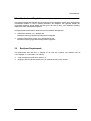
2.4 Hardware Requirements
The Spinpoint M9T hard disk drive is designed for use with host computers and controllers that are
ATA compatible. It is connected to a PC either by:
Using an adapter board with SATA interface, or
Plugging a cable from the drive directly into a PC motherboard with a SATA interface

Spinpoint M9T Product Manual REV 1.0
6
SPECIFICATIONS
CHAPTER 3 SPECIFICATIONS
This chapter gives a detail description of the physical, electrical and environmental characteristics of the Spinpoint M9T
hard disk drive.
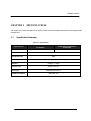
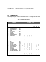
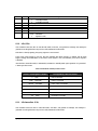
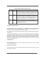
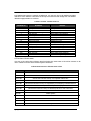
3.1 Specification Summary
Table 3-1:
Specifications
DESCRIPTION
ST1500LM006 , ST1500LM007 &
ST1500LM010
ST2000LM003, ST2000LM004 &
ST2000LM006
Number of R/W heads
5/6 6
Maximum KBPI
2731
Flexible data TPI
480K
Encoding method
LDPC (low density parity check) encoding
Interface
SATA 6.0 Gbps
(3.0Gbps, 1.5 Gbps
)
Actuator type
Rotary Voice
Coil
Servo type
Embedded Sector
Servo
Spindle speed (RPM)
5400 RPM
Class

Spinpoint M9T Product Manual REV 1.0
7
SPECIFICATIONS
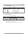
3.2 Physical Specifications
Table 3-2: Physical Specifications
DESCRIPTION
ST1500LM006 , ST1500LM007 &
ST1500LM010
ST2000LM003, ST2000LM004 &
ST2000LM006
Physical dimensions
Length
Width
Height
Weight (max)
100.35 +0.2/-0.25mm [3.951+0.008/-0.010 inch]
69.85 ±
0.25
mm [2.75 ± 0.010 inch]
9.5 ±
0.2
mm [0.374 ± 0.008 inch]
3-Disk 130 g [0.29 lb]
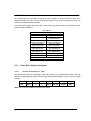
3.3 Logical Configurations
Table 3-3: Logical Configurations
* 1MB = 1,000,000 Bytes, 1GB = 1,000,000,000 Bytes
* Accessible capacity may vary as some OS uses binary numbering system for reported capacity.
DESCRIPTION
ST1500LM006 , ST1500LM007 &
ST1500LM010
ST2000LM003, ST2000LM004 &
ST2000LM006
Total Number of logical sectors
2,930,277,168
3,907,029,168
Capacity
1.5TBB 2TB

Spinpoint M9T Product Manual REV 1.0
8
SPECIFICATIONS
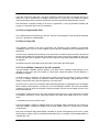
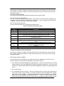
3.4 Performance Specifications
Table 3-4: Performance Specifications
NOTES: Seek time is defined as the time from the receipt of a read, write or seek command until the actuator has
repositioned and settled on the desired track with the drive operating at nominal DC input voltages and
nominal operating temperature.
• Average seek time is determined by averaging the time to complete 1,000 seeks of random length.
• Average latency is the time required for the drive to rotate 1/2 of a revolution and on average is incurred after
a seek completion prior to reading or writing user data.
• Startup time is the time elapsed between the supply voltages reaching operating range and the drive being
ready to accept all commands.
• Actual rotational speed can be different a little.
• Performance specification is limited to the room temperature & normal voltage condition.
DESCRIPTION
ST1500LM006 , ST1500LM007 &
ST1500LM010
ST2000LM003, ST2000LM004 &
ST2000LM006
Seek Time (RD/WRT,
Typ)
Average seek time
Track to track seek time
Full stroke seek time
12/14 ms
2/4 ms
22/24 ms
`
Average Latency
5.6 ms
Data Transfer Rate
(Max)
buffer to/from
media
host to/from buffer
169MB/s
600 MB/s
Rotational Speed
5400 RPM Class
Startup Time (Typ)
Power on to Drive Ready
Standby to
Drive Ready
3.5 sec
2.5 sec

Spinpoint M9T Product Manual REV 1.0
9
SPECIFICATIONS
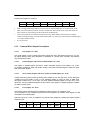
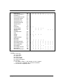
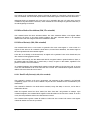
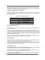
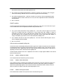
3.5 Power consumption
Table 3-5: Power consumption
DESCRIPTION
ST1500LM006 , ST1500LM007 &
ST1500LM010
ST2000LM003, ST2000LM004 &
ST2000LM006
Rated
Voltage V
+5
Current A
0.85
Power Consumption
Start Up
mA
1000
Low Power Idle
Watt
0.7
Read/Write
Watt
2.3
Seek
Watt
2.0
Stand by
Watt
0.18
Sleep
Watt
0.18
Power Requirements
Tolerance For + 5V
%
+/-
5
Ripple, 0-30MHz
mV
p-p
100
Supply Rise Time
us/
msec
10us-100ms
Supply Fall Time
Sec
<
5
1) Random seek: 30% Duty cycle seek commands with logical random location.
2) Read/Write: Avg. Read/Write operation at OD for 32 sectors.
3) All the power should be measured at the room temperature and normal voltage condition.

Spinpoint M9T Product Manual REV 1.0
10
SPECIFICATIONS
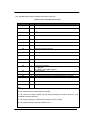
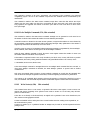
3.6 Environmental Specifications
Table 3-6: Environmental Specifications
DESCRIPTION
ST1500LM006 , ST1500LM007 &
ST1500LM010
ST2000LM003, ST2000LM004 &
ST2000LM006
Ambient Temperature
Operating
Non-operating
Max. gradient
(Temperature/Humidity)
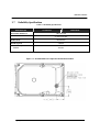
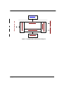
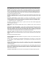
(Drive temperature measured on position of figure 3-1 on page 11,
should be max 65C in range of 0°C -60°C, specified operation temperature.)
0°C
~
60°C
-40°C
~
70°C
20°C / 20%/hr
Relative Humidity (non condensing)
Operation
Non-operation
Maximum wet bulb temperature
Operating
Non-operating
5~90 %
5~95 %
30°C
40°C
Altitude (relative to sea level)
Operating
Non-operating
-304.8 m to 3,048 m
-304.8 m to 12,192 m
Vibration
Operating :
10-500 Hz, Random
Non-operating :
10-500 Hz, Random
1.5 Grms
5.85 Grms
Linear Shock (1/2 sine pulse)
Operating 2.0 ms
Non-operating 1.0 ms
Rotational Shock
Operating 2.0 ms
Non-operating 2.0 ms
300G
900G
3K rad/sec 2
30K rad/sec 2
Acoustic
Noise
(Typical Sound Power)
Idle
Seek
2.5
Bels
2.7
Bels

Spinpoint M9T Product Manual REV 1.0
11
SPECIFICATIONS
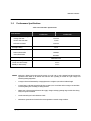
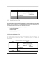
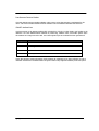
3.7 Reliability Specifications
Table 3-7: Reliability
Specifications
DESCRIPTION
ST1500LM006
, ST1500LM007 &
ST1500LM010
ST2000LM003, ST2000LM004 &
ST2000LM006
Recoverable Read Error
<10 in 10
11
bits
Non-Recoverable Read Error
<1 sector in 10
14
bits
MTBF (POH)
550,000 hours
MTTR (Typical)
5 minutes
Load/Unload Cycles
Ambient
600,000
Figure 3-1:
Recommended Case Temperature Measurement Position

Spinpoint M9T Product Manual REV 1.0
13
INSTALLATION
CHAPTER 4 INSTALLATION
This chapter describes how to unpack, mount, configure and connect a Spinpoint M9T hard disk drive.
It also describes how to install the drive in systems.
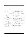
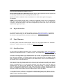
4.1 Space Requirements
Refer to Figure 4-2 on page 15.

Spinpoint M9T Product Manual REV 1.0
14
INSTALLATION
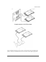
4.2 Unpacking Instructions
(1) Open the shipping container of the Spinpoint M9T hard disk drive.
(2) Lift the packing assembly that contains the drive out of the shipping container.
(3) Remove the drive from the packing assembly. When you are ready to install the drive, remove it from
the ESD (Electro Static Discharge) protection bag. Take precautions to protect the drive from ESD
damage after removing it from the bag.
CAUTION: During shipment and handling, the anti-static ESD protection bag
prevents electronic component damage due to electrostatic discharge.
To avoid accidental damage to the drive, do not use a sharp instrument to
open the ESD protection bag.
(4) Save the packing material for possible future use.
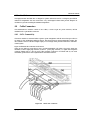
4.3 Mounting
Refer to your system manual for complete mounting details.
(1) Be sure that the system power is off.
(2) For mounting, use four M3 screws.
CAUTION: Torque applied to the screws is recommended to
be 3.5 [kg* cm]
±0.5 (
3.0 [inch *pounds] ± 0.5)

Spinpoint M9T Product Manual REV 1.0
15
INSTALLATION
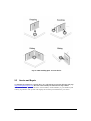
4.3.1 Orientation
Figure 4-2 shows the physical dimensions and mounting holes located on each side of the drive. The
mounting holes on Spinpoint M9T hard disk drive allow the drive to be mounted in any direction.
Figure 4-2:
Mounting
Dimensions
Page is loading ...
Page is loading ...
Page is loading ...
Page is loading ...
Page is loading ...
Page is loading ...
Page is loading ...
Page is loading ...
Page is loading ...
Page is loading ...
Page is loading ...
Page is loading ...
Page is loading ...
Page is loading ...
Page is loading ...
Page is loading ...
Page is loading ...
Page is loading ...
Page is loading ...
Page is loading ...
Page is loading ...
Page is loading ...
Page is loading ...
Page is loading ...
Page is loading ...
Page is loading ...
Page is loading ...
Page is loading ...
Page is loading ...
Page is loading ...
Page is loading ...
Page is loading ...
Page is loading ...
Page is loading ...
Page is loading ...
Page is loading ...
Page is loading ...
Page is loading ...
Page is loading ...
Page is loading ...
Page is loading ...
Page is loading ...
Page is loading ...
Page is loading ...
Page is loading ...
Page is loading ...
Page is loading ...
Page is loading ...
Page is loading ...
Page is loading ...
Page is loading ...
Page is loading ...
Page is loading ...
Page is loading ...
Page is loading ...
Page is loading ...
Page is loading ...
Page is loading ...
Page is loading ...
Page is loading ...
Page is loading ...
-
 1
1
-
 2
2
-
 3
3
-
 4
4
-
 5
5
-
 6
6
-
 7
7
-
 8
8
-
 9
9
-
 10
10
-
 11
11
-
 12
12
-
 13
13
-
 14
14
-
 15
15
-
 16
16
-
 17
17
-
 18
18
-
 19
19
-
 20
20
-
 21
21
-
 22
22
-
 23
23
-
 24
24
-
 25
25
-
 26
26
-
 27
27
-
 28
28
-
 29
29
-
 30
30
-
 31
31
-
 32
32
-
 33
33
-
 34
34
-
 35
35
-
 36
36
-
 37
37
-
 38
38
-
 39
39
-
 40
40
-
 41
41
-
 42
42
-
 43
43
-
 44
44
-
 45
45
-
 46
46
-
 47
47
-
 48
48
-
 49
49
-
 50
50
-
 51
51
-
 52
52
-
 53
53
-
 54
54
-
 55
55
-
 56
56
-
 57
57
-
 58
58
-
 59
59
-
 60
60
-
 61
61
-
 62
62
-
 63
63
-
 64
64
-
 65
65
-
 66
66
-
 67
67
-
 68
68
-
 69
69
-
 70
70
-
 71
71
-
 72
72
-
 73
73
-
 74
74
-
 75
75
-
 76
76
-
 77
77
-
 78
78
-
 79
79
-
 80
80
-
 81
81


Ask a question and I''ll find the answer in the document
Finding information in a document is now easier with AI
Related papers
Other documents
-
Conceptronic C05-110 Datasheet
-
Seagate Samsung Spinpoint M Series User manual
-
 Micromat Drive Scope Operating instructions
-
Transcend TS128GMSM360 Datasheet
-
-
takeMS MS128SDC010 Datasheet
-
Toshiba MK2008GAL User manual
-
-
-
