Page is loading ...

Not for Reproduction
48V Cordless String Trimmer
Read all safety rules and instructions carefully before operating this tool.
Owner’s Manual
TOLL-FREE HELPLINE: 1-800-317-7833
www.snapper.com
1696956 & 80075680 / ST48
1687970 / ST48K

Not for Reproduction
2
CONTENTS
Contents .................................................................................................. 2
......................................................................................... 2
Imp
ortant Safety Instructions .................................................................. 3
Symbols .................................................................................................. 6
Know Your String Trimmer ....................................................................... 8
Assembly ...............................................................................................10
Operation ...............................................................................................16
Maintenance.......................................................................................
24
Environmentally Safe Battery Disposal...............................................25
Troubleshooting...........................................................................................26
Warranty....................................................................................28
Exploded view.........................................................................30
Parts list.....................................................................................31
SPECIFICATIONS
48V 13'' STRING TRIMMER
Type ................................................................. Cordless, battery powered
Motor ............................................................................................. 48V DC
Cutting Width .............................................................11/13 in. (27.9/33.0 cm)
Line Diameter............................................................Nylon / .080" (2.0 mm)
Speed (max).......................................................6900±10%/6300±10% RPM
Feed Type
.....................................................................................Bump Feed
Weight (without battery)...........................................................6.8 lbs (3.1 kg)
Disclaimer: *Maximum initial battery voltage (measured without a workload) is
48 volts. Nominal voltage is 43.

Not for Reproduction
3
IMPORTANT SAFETY INSTRUCTIONS
WARNING
Read and understand all instructions before using this product. Failure
serious personal injury.
• Use only identical manufacturer’s replacement parts and accessories. Use
of any other parts may create a hazard or cause product damage.
• Always wear safety glasses with side shields marked to comply with ANSI
Z87.1. Everyday glasses have only impact resistant lenses. They are NOT
safety glasses. Following this rule will reduce the risk of eye injury. Use face
mask if operating in dusty work spaces.
• Avoid Dangerous Environment — Don’t expose power tools to damp or
wet conditions. Water entering a power tool will increase the risk of electric
shock.
• Don’t use in rain.
• Keep all bystanders, children, and pets at least 50 ft. away.
• Do not use the power tools for any job except that for which it is intended.
•
the switch. Be sure the battery is removed while transporting.
• Do not operate the equipment while barefoot or when wearing sandals or
similar lightweight footwear. Wear protective footwear that will protect your
feet and improve your footing on slippery surfaces.
• Don’t overreach - Keep proper footing and balance at all times.
• Stay alert - Watch what you are doing. Use common sense. Do not operate
medication.
• Always store idle power tools indoors - When not in use, power tools should
be stored indoors in a dry place, out of reach of children.
• Power tool maintenance – Replace string head if cracked, chipped, or
damaged in any way. Be sure the string head is properly installed and
securely fastened. Keep cutting edge sharp and clean for best performance
and to reduce the risk of injury. Follow instructions for lubricating and
changing accessories. Inspect appliance cord periodically, and if damaged,
have it repaired by an authorized service facility. Inspect extension cords
periodically and replace if damaged. Keep handles dry, clean, and free from
oil and grease. Failure to do so can cause serious injury.
• Check Damaged Parts – Before further use of the appliance, a guard or
other part that is damaged should be carefully checked to determine that it
will operate properly and perform its intended function. Check for alignment
of moving parts, binding of moving parts, breakage of parts, damaged

Not for Reproduction
4
IMPORTANT SAFETY INSTRUCTIONS
mountings, and any other condition that may affect its operation. A guard
or other part that is damaged should be properly repaired or replaced by an
authorized service center unless indicated elsewhere in this manual.
• Do not charge or operate cordless tools in damp or wet locations or in the
rain. Following this rule will reduce the risk of electric shock.
• Remove or disconnect battery before servicing, cleaning or removing
material from the gardening appliance.
•
local codes for possible special disposal instructions.
• Do not open or mutilate the batteries. Released electrolyte is corrosive and
may cause damage to the eyes or skin. It may be toxic if swallowed.
• Exercise care in handling batteries in order not to short the battery with
conducting materials such as rings, bracelets, and keys. The battery or
conductor may overheat and cause burns.
• Dress Properly – Do not wear loose clothing or jewelry. They can be
caught in moving parts. Use of rubber gloves and substantial footwear is
recommended when working outdoors. Wear protective hair covering to
contain long hair.
• Do not add unnecessary force to your power tool – It will do the job better
and with less likelihood of a risk of injury at the rate for which it was
designed.
• Recharge only with the charger specified by the manufacturer. A charger
used with another battery pack.
• Use only Briggs & Stratton batteries: BSB2AH48 or BSB5AH48.
• Use only Briggs & Stratton charger: BS2AC48.
• When battery pack is not in use, keep it away from other metal objects,
like paper clips, coins, keys, nails, screws or other small metal objects, that
can make a connection from one terminal to another. Shorting the battery
• Under abusive conditions, liquid may be ejected from the battery; avoid
contact. If contact accidentally occurs, flush with water. If liquid contacts
eyes, additionally seek medical help. Liquid ejected from the battery may
cause irritation or burns.
• Do not use a battery pack or appliance that is damaged or modified.
•
explosion.

Not for Reproduction
5
IMPORTANT SAFETY INSTRUCTIONS
• Follow all charging instructions and do not charge the battery pack or
appliance outside of the temperature range specified in the instructions.
•
replacement parts. This will ensure that the safety of the product is
maintained.
• Prevent unintentional starting. Ensure the switch is in the off-position before
connecting to battery pack, picking up or carrying the appliance which will
have the switch on would invite accidents.
• Disconnect applicance- Remove the battery when not in use, before
servicing, when changing accessories such as blade, and the like.
•
• Do not modify or attempt to repair the appliance or the battery pack except
as indicated in the instructions for use and care.
W A R N I N G (PROPOSITION 65)
Some dust created by power sanding, sawing, grinding, drilling, and other
construction activities contains chemicals known to cause cancer, birth defects
or other reproductive harm. Some examples of these chemicals are:
• Lead from lead-based paints
• Crystalline silica from bricks and cement and other masonry products,
and
• Arsenic and chromium from chemically treated lumber.
Your risk of exposure to these chemicals varies depending on how often you do
this type of work. To reduce your exposure to these chemicals, work in a well-
ventilated area, and work with approved safety equipment, such as dust masks
SAVE THESE INSTRUCTIONS

Not for Reproduction
6
Some of the following symbols may be used on this product. Please study them
and learn their meaning. Proper interpretation of these symbols will allow you to
operate the product better and safer.
SYMBOL NAME DESIGNATION/EXPLANATION
V
Volts Voltage
min
Minutes Time
Direct Current Type or a characteristic of current
No Blade
Do not install or use any type of
blade on a product or displaying this
symbol.
Wet Conditions Alert
Do not expose to rain or use in damp
locations.
Read The Operator’s
Manual
To reduce the risk of injury user must
read and understand operator’s
manual before using this product.
Eye Protection
Always wear eye protection with side
shields marked to comply with ANSI
Z87.1 when operating this equipment.
Safety Alert Precautions that involve your safety.
Ricochet
Thrown objects can ricochet and
result in personal injury or property
damage.
Keep Bystanders Away
Keep all bystanders at least 50 ft.
away.
SYMBOLS

Not for Reproduction
The following signal words and meanings are intended to explain the levels of
risk associated with this product.
SYMBOL SIGNAL MEANING
DANGER
Indicates an imminently hazardous situation,
which, if not avoided, will result in death or
serious injury.
WARNING
Indicates a potentially hazardous situation,
which, if not avoided, could result in death or
serious injury.
CAUTION
Indicates a potentially hazardous situation,
which, if not avoided, may result in minor or
moderate injury.
CAUTION
(Without Safety Alert Symbol) Indicates a
situation that may result in property damage.
SERVICE
Servicing requires extreme care and knowledge and should be performed
product to your nearest AUTHORIZED SERVICE CENTER for repair. Use
only identical manufacturer’s replacement parts and accessories.
WARNING
To avoid serious personal injury, do not attempt to use this product until you
have read this Owner's Manual thoroughly and understand it completely. If you
do not understand the warnings and instructions in this Owner's Manual, do not
use this product. Call the Toll-free Helpline (1-800-317-7833) for assistance.
WARNING
The operation of any power tool can result in foreign objects being
thrown into your eyes, which can result in severe eye damage. Before
beginning power tool operation, always wear safety goggles or safety
glasses with side shields and, when needed, a full face shield. We
recommend Wide Vision Safety Mask for use over eyeglasses or
standard safety glasses with side shields. Always use eye protection
which is marked to comply with ANSI Z87.1.
SYMBOLS
SAVE THESE INSTRUCTIONS
7

Not for Reproduction
8
KNOW YOUR STRING TRIMMER
Fig. 1

Not for Reproduction
9
KNOW YOUR STRING TRIMMER (See Figure 1.)
The safe use of this product requires an understanding of the information on
the product and in this operator’s manual as well as a knowledge of the project
you are attempting. Before use of this product, familiarize yourself with all
operating features and safety rules.
1. REAR HANDLE
Ergonomic handle with overmold improves comfort and grip.
2. SAFETY LOCK-OUT TRIGGER
The safety lock-out trigger prevents accidental starting.
3. HIGH/LOW SPEED BUTTON
Set the speed to low for greater runtime and high for quicker cutting.
4. TRIGGER
Activates the string trimmer when pulled.
5. AUXILIARY HANDLE
The string trimmer is equipped with an auxiliary handle for added control and
ease of operation.
6. COUPLER
The coupler connects and locks the two shafts.
7. EDGE GUIDE
8. CUT-OFF BLADE
Adjustable steel blade on the guard keeps the cutting line at the proper
cutting length.
9. GUARD
KNOW YOUR STRING TRIMMER

Not for Reproduction
10
ASSEMBLY
WARNING
Do not use this product if any parts on the packing list are already assembled
to your product when you unpack it. Parts on this list are not assembled to the
product by the manufacturer and require customer installation. Use of a product
that may have been improperly assembled could result in serious personal
injury.
PACKING LIST
Part Name Figure Qty
String Trimmer
1
Auxiliary
handle
1
Guard
1
Edge guide
1
Operator's
Manual
1
UNPACKING
This product requires assembly.
• Carefully remove the product and any accessories from the box. Make sure
that all items listed in the packing list are included.
• Inspect the tool carefully to make sure no breakage or damage occurred
during shipping.
• Do not discard the packing material until you have carefully inspected and
satisfactorily operated the tool.
• If any parts are damaged or missing, please call 1-800-317-7833.
Not for Reproduction
ASSEMBLY
11
WARNING
If any parts are damaged or missing, do not operate this product until the parts
are replaced. Use of this product with damaged or missing parts could result
in serious personal injury.
WARNING
Do not attempt to modify this product or create accessories not recommended
and could result in a hazardous condition leading to possible serious personal
injury.
WARNING
Do not connect to power supply until assembly is complete. Failure to comply
could result in accidental starting and possible serious personal injury.
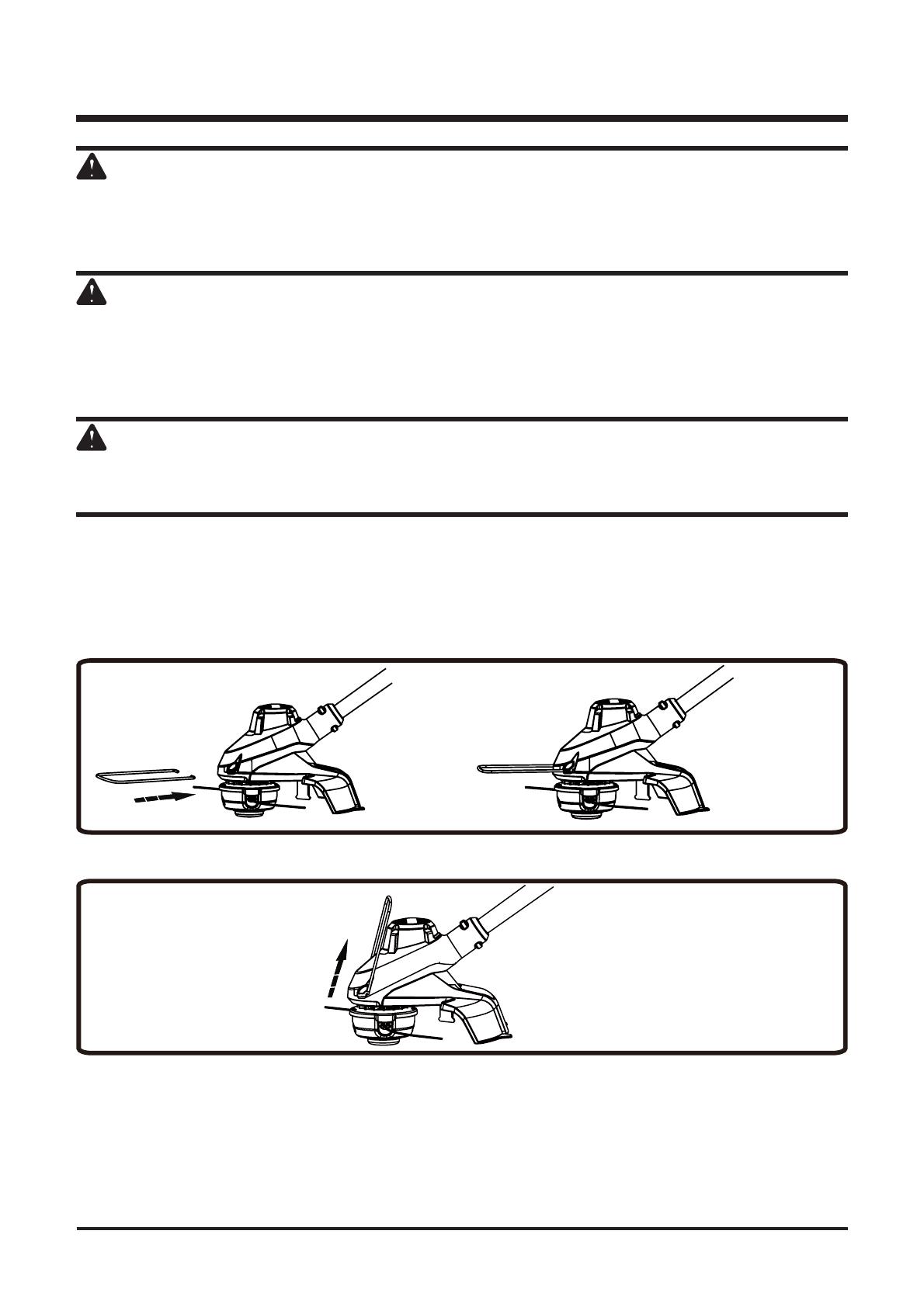
ATTACH THE EDGE GUIDE (
See
Figures 2.1 and 2.2)
The edge guide can limit the cutting range of the trimmer and reduce the risk
of the rotating cutting line causing damage.
1. To use the edge guide, press the edge guide onto the trimmer head.
2.
Fig. 2.1
Fig. 2.2

Not for Reproduction
ATTACH THE GUARD (
See
Figures 3.1 - 3.3)
NOTE: Install the guard before the attachment is connected to the lower shaft.
1. Invert the string trimmer to access the trimmer head.
2. Remove supplied screws (1) from the guard with a philips screwdriver (not
included).
1
3. Slide the guard (1) into the slots on the trimmer head.
4. Align the screw holes on the guard (2) with the screw holes on the trimmer
head (3).
1
3
2
5. Insert the screws into the trimmer head, fastening the guard in place
using a philips head screwdriver (not included).
ASSEMBLY
12
Fig. 3.1
Fig. 3.2
Fig. 3.3
Not for Reproduction
ASSEMBLY
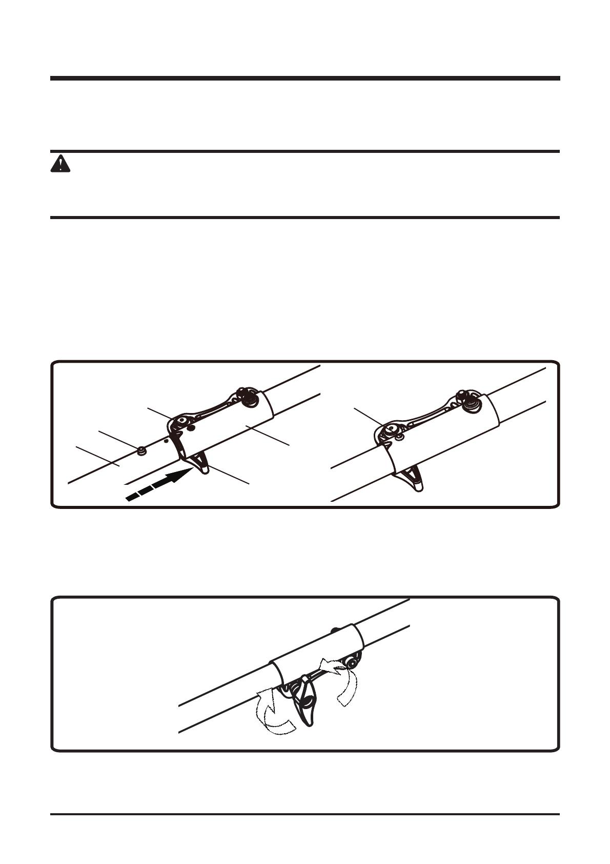
INSTALL THE UPPER SHAFT TO THE LOWER SHAFT
(See Figures 4.1 and 4.2)
WARNING
Never install, remove, or adjust any attachment while string trimmer is running.
Failure to stop the motor can cause serious personal injury.
The attachment connects to the power head by means of a coupler device.
1.
2. Loosen the knob (1) on the coupler (5).
3. Push in the release button (2) located on the lower shaft (3). Align the
release button with the positioning hole (4) and slide the two shafts
together. Rotate the lower shaft until the button locks into the positioning
hole.
1
5
4
2
3
2
NOTE: If the button does not release completely in the positioning hole, the
shafts are not locked into place. Slightly rotate from side to side until the
button is locked into place.
4. Tighten the knob securely.
Fig. 4.2
Loosen
Tighten
13
Fig. 4.1

Not for Reproduction
14
ATTACH THE AUXILIARY HANDLE (See Figures 5.1 and 5.2)
1. Loosen the two screws (1) in the handle with a philips screwdriver (not
included) and remove the screws from the handle.
Fig. 5.1
1
2. Attach the auxiliary handle (2) and lower clamp (3) on the shaft.
3. Adjust handle up or down, if necessary, to desired operating position.
Fig. 5.2
2
3
4. Insert and tighten the two screws so that the handle cannot be rotated on
the shaft.
ASSEMBLY

Not for Reproduction
ADJUST THE CUTTING SWATH (See Figure 6.)
This trimmer is equipped with a line cut-off blade on the guard. The line cut
off blade continuously trims the line to ensure a consistent and efficient
cut diameter. Advance line whenever you hear the engine running faster
performance and keep line long enough to advance properly.
This trimmer is currently set at the 11 in. cutting swath. To adjust to a cutting
swath of 13 in.:
1. Remove the battery pack.
2.
3. Tighten the blade screw.
ASSEMBLY
Screw
Cut-off blade
Fig. 6
15

Not for Reproduction
16
OPERATION
WARNING
Do not allow familiarity with this product to make you careless. Remember that
WARNING
Do not use any attachments or accessories not recommended by the
manufacturer of this product. The use of attachments or accessories not
recommended can result in serious personal injury.
WARNING
This string trimmer is not meant to be used with brush cutter attachments. Use
of a brush cutter attachment could cause serious personal injuries or property
damage.
Not for Reproduction
17
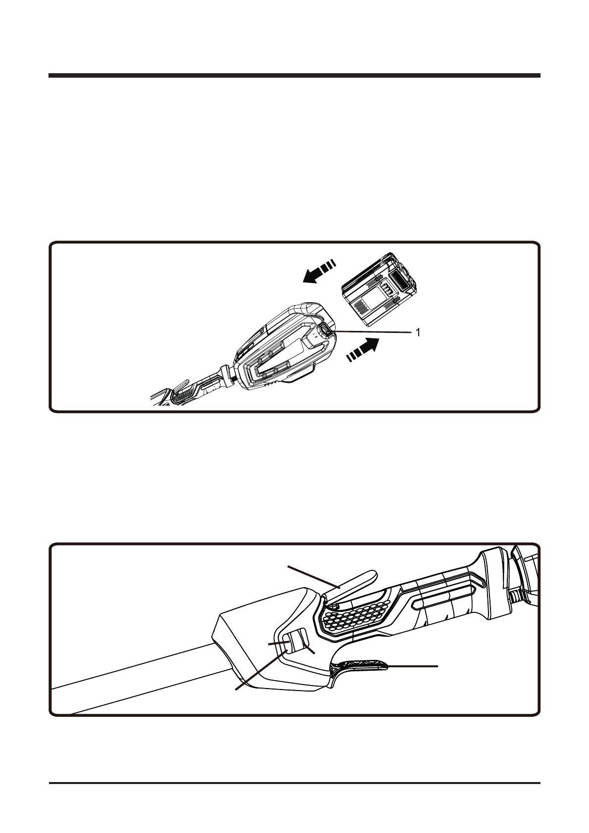
INSTALLING THE BATTERY PACK (See Figure 7.)
• Align raised ribs on battery pack with grooves in the trimmer’s battery port.
• Make sure the latch on the battery pack clicks into place and the battery
pack is fully seated and secured in the trimmer before beginning operation.
REMOVING THE BATTERY PACK (See Figure 7.)
• Depress the battery release button (1) in the back of the battery pack and
pull the battery pack out of the tool.
STARTING AND STOPPING THE TRIMMER (See Figure 8.)
• Slide the speed switch (1) to the desired operating speed. Slide the speed
switch to position 1 for low speed or position 2 for high speed.
• Press the safety lock trigger (2). Squeeze the trigger (3) to start.
• Release the trigger to stop.
1
2
3
OPERATION
Fig. 7
Fig. 8
Not for Reproduction
18
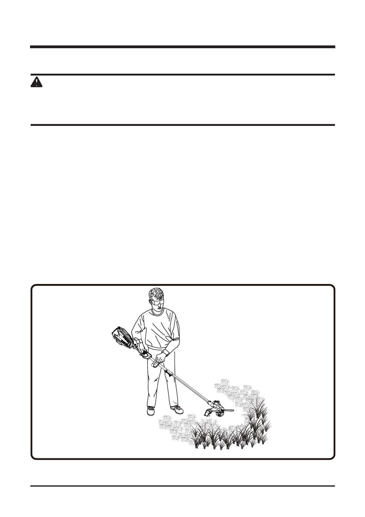
OPERATING THE TRIMMER (See Figure 9.)
WARNING
Always hold the string trimmer away from the body keeping clearance between
the body and the string trimmer. Any contact with the string trimmer cutting
head while operating can result in serious personal injury.
Follow these tips when using the string trimmer:
• Hold the trimmer with your right hand on the rear handle and your left hand
on the auxiliary handle.
•
• Trimmer should be held at a comfortable position with the rear handle about
hip height.
• Cut tall grass from the top down. This will prevent grass from wrapping
around the shaft housing and string head which may cause damage from
overhearing.
If grass becomes wrapped around the string head:
• Remove the battery pack.
• Remove the grass.
OPERATION
Fig. 9
Not for Reproduction
19
OPERATION
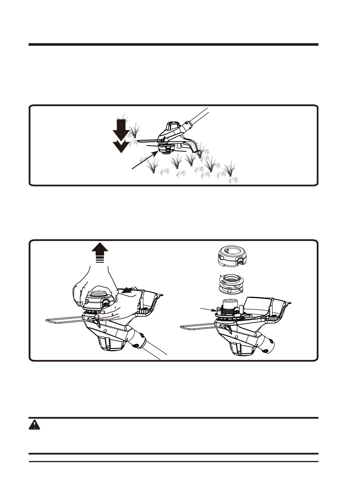
ADVANCING LINE (See Figure 10.)
While the string trimmer is operating, the cutting line gets worn down and
becomes shorter. This trimmer is equipped with bump feed line advancement,
which advances additional line once the head is bumped on the ground while
rotating. The cutting blade will cut the line to keep an accurate cutting swath.
SPOOL REPLACEMENT (See Figures 11.1 - 11.7)
1. Remove the battery pack from the tool.
2. Press the tabs simultaneously on the side of the trimmer head and
remove cover and spool.
3. Remove any remaining line.
4. Clean dirt and debris from all parts. Replace spool if it is worn or
damaged.
5. Replace with a pre-wound spool, or replace line using 15 feet (4.6
meters) of 0.080 inch (2.0 mm) diameter line.
WARNING
Never use wire, rope, string, etc., which can break off and become a dangerous
projectile.
Cover
Spool
Tab
Fig. 11.1
Bump head
Fig. 10

Not for Reproduction
20
OPERATION
6. When installing new line on an existing spool, hold the spool as shown.
7. Bend the line at the midpoint and insert the bend into the slot in the center
rim of the spool. Make sure that the line snaps into position in the slot
8.
around the spool in a clockwise direction.
Fig. 11.3
9. Position the lines in the guide slots.
Fig. 11.4
/