Page is loading ...

PB
USER’S MANUAL
Revision 1.0
SuperServer
®
5019P-WT
5019P-WTR
The information in this User’s Manual has been carefully reviewed and is believed to be accurate. The vendor assumes
no responsibility for any inaccuracies that may be contained in this document, and makes no commitment to update
or to keep current the information in this manual, or to notify any person or organization of the updates. Please Note:
For the most up-to-date version of this manual, please see our website at www.supermicro.com.
Super Micro Computer, Inc. ("Supermicro") reserves the right to make changes to the product described in this manual
at any time and without notice. This product, including software and documentation, is the property of Supermicro and/
or its licensors, and is supplied only under a license. Any use or reproduction of this product is not allowed, except
as expressly permitted by the terms of said license.
IN NO EVENT WILL Super Micro Computer, Inc. BE LIABLE FOR DIRECT, INDIRECT, SPECIAL, INCIDENTAL,
SPECULATIVE OR CONSEQUENTIAL DAMAGES ARISING FROM THE USE OR INABILITY TO USE THIS PRODUCT
OR DOCUMENTATION, EVEN IF ADVISED OF THE POSSIBILITY OF SUCH DAMAGES. IN PARTICULAR, SUPER
MICRO COMPUTER, INC. SHALL NOT HAVE LIABILITY FOR ANY HARDWARE, SOFTWARE, OR DATA STORED
OR USED WITH THE PRODUCT, INCLUDING THE COSTS OF REPAIRING, REPLACING, INTEGRATING,
INSTALLING OR RECOVERING SUCH HARDWARE, SOFTWARE, OR DATA.
Any disputes arising between manufacturer and customer shall be governed by the laws of Santa Clara County in the
State of California, USA. The State of California, County of Santa Clara shall be the exclusive venue for the resolution
of any such disputes. Supermicro's total liability for all claims will not exceed the price paid for the hardware product.
FCC Statement: This equipment has been tested and found to comply with the limits for a Class A digital device
pursuant to Part 15 of the FCC Rules. These limits are designed to provide reasonable protection against harmful
interference when the equipment is operated in a commercial environment. This equipment generates, uses, and can
radiate radio frequency energy and, if not installed and used in accordance with the manufacturer’s instruction manual,
may cause harmful interference with radio communications. Operation of this equipment in a residential area is likely
to cause harmful interference, in which case you will be required to correct the interference at your own expense.
California Best Management Practices Regulations for Perchlorate Materials: This Perchlorate warning applies only
to products containing CR (Manganese Dioxide) Lithium coin cells. “Perchlorate Material-special handling may apply.
See www.dtsc.ca.gov/hazardouswaste/perchlorate”.
WARNING: Handling of lead solder materials used in this product may expose you to lead, a
chemical known to the State of California to cause birth defects and other reproductive harm.
The products sold by Supermicro are not intended for and will not be used in life support systems, medical equipment,
nuclear facilities or systems, aircraft, aircraft devices, aircraft/emergency communication devices or other critical
property damage. Accordingly, Supermicro disclaims any and all liability, and should buyer use or sell such products
for use in such ultra-hazardous applications, it does so entirely at its own risk. Furthermore, buyer agrees to fully
indemnify, defend and hold Supermicro harmless for and against any and all claims, demands, actions, litigation, and
proceedings of any kind arising out of or related to such ultra-hazardous use or sale.
Manual Revision 1.0
Release Date: August 02, 2017
Unless you request and receive written permission from Super Micro Computer, Inc., you may not copy any part of this
to herein are trademarks or registered trademarks of their respective companies or mark holders.
Copyright © 2017 by Super Micro Computer, Inc.
All rights reserved.
Printed in the United States of America

433
PrefaceSuperServer 5019P-WT/WTR User's Manual
Preface
About this Manual
This manual is written for professional system integrators and PC technicians. It provides
information for the installation and use of the SuperServer 5019P-WT/WTR. Installation and
maintainance should be performed by experienced technicians only.
supported memory, processors and operating systems (http://www.supermicro.com).
Notes
For your system to work properly, please follow the links below to download all necessary
drivers/utilities and the user’s manual for your server.
• Supermicro product manuals: http://www.supermicro.com/support/manuals/
• Product drivers and utilities: ftp://ftp.supermicro.com
• Product safety info: http://www.supermicro.com/about/policies/safety_information.cfm
If you have any questions, please contact our support team at:
This manual may be periodically updated without notice. Please check the Supermicro website
for possible updates to the manual revision level.
Warnings
Special attention should be given to the following symbols used in this manual.
Warning! Indicates high voltage may be encountered when performing a procedure.
Warning! Indicates important information given to prevent equipment/property damage
Contents
Chapter 1 Introduction
1.1 Overview ...............................................................................................................................8
1.2 Unpacking the System .........................................................................................................8
1.3 System Features ..................................................................................................................9
1.4 Server Chassis Features ....................................................................................................10
Control Panel ....................................................................................................................10
Chassis Front ....................................................................................................................11
Chassis Rear .....................................................................................................................12
1.5 Motherboard Layout ...........................................................................................................13
Quick Reference Table ......................................................................................................14
Chapter 2 Server Installation
2.1 Overview .............................................................................................................................17
2.2 Preparing for Setup ............................................................................................................17
Choosing a Setup Location ...............................................................................................17
Rack Precautions ..............................................................................................................17
Server Precautions ............................................................................................................18
Rack Mounting Considerations .........................................................................................18
Ambient Operating Temperature ....................................................................................18
............................................................................................................................18
Mechanical Loading .......................................................................................................18
Circuit Overloading ........................................................................................................19
Reliable Ground .............................................................................................................19
2.3 Installing the Rails ..............................................................................................................20
Identifying the Sections of the Rack Rails ........................................................................20
Installing the Inner Rails ...................................................................................................20
Installing the Outer Rails ...................................................................................................21
2.4 Installing the Server into a Rack ........................................................................................22
Installing to a Standard Rack ............................................................................................22
Installing to a Telco Rack ..................................................................................................23
Chapter 3 Maintenance and Component Installation
3.1 Removing Power ................................................................................................................24
3.2 Accessing the System ........................................................................................................24

65
PrefaceSuperServer 5019P-WT/WTR User's Manual
3.3 Motherboard Components ..................................................................................................25
Processor and Heatsink Installation ..................................................................................25
The Intel Xeon 81xx/61xx/51xx/41xx/31xxSeries Processor ...........................................25
Overview of the Processor Socket Assembly ...................................................................26
Overview of the Processor Heatsink Module (PHM) ........................................................27
Attaching the Non-F Model Processor to the Processor Clip to Create the Processor
Carrier Assembly ...............................................................................................................28
Attaching the Non-F Model Processor Carrier Assembly to the Heatsink to Form the
Processor Heatsink Module (PHM) ...................................................................................29
Preparing the CPU Socket for Installation ........................................................................30
Removing the Dust Cover from the CPU Socket .............................................................30
Installing the Processor Heatsink Module (PHM) ............................................................31
Removing the Processor Heatsink Module (PHM) from the Motherboard .......................32
Memory Installation ...........................................................................................................33
Memory Support ............................................................................................................33
DIMM Module Population Sequence ................................................................................34
DIMM Installation ..............................................................................................................35
DIMM Removal .................................................................................................................35
PCI Expansion Card Installation .......................................................................................36
Daughter Cards .................................................................................................................38
Motherboard Battery .........................................................................................................38
3.4 Chassis Components .........................................................................................................39
Front Bezel ........................................................................................................................39
Hard Drives .......................................................................................................................39
Hard Drive Carrier Indicators .........................................................................................40
System Cooling .................................................................................................................42
Installing Fans ................................................................................................................42
.........................................................................................................43
Power Supply ....................................................................................................................44
Power Supply Failure ........................................................................................................44
Chapter 4 Motherboard Connections
Data Cables ...................................................................................................................46
4.1 Power Connections ............................................................................................................46
4.2 Front Control Panel ............................................................................................................48
4.3 Ports and Headers .............................................................................................................50
Rear I/O Ports ...................................................................................................................50
Connectors ........................................................................................................................53
Headers .............................................................................................................................54
4.4 Jumpers ..............................................................................................................................57
Explanation of Jumpers .................................................................................................57
4.5 LED Indicators ....................................................................................................................59
Chapter 5 Software
5.1 OS Installation ....................................................................................................................61
Installing the Windows OS for a RAID System ................................................................61
Installing Windows to a Non-RAID System ......................................................................61
5.2 Driver Installation ................................................................................................................62
5.3 SuperDoctor
®
5 ...................................................................................................................63
5.4 IPMI ....................................................................................................................................64
Chapter 6 BIOS
6.1 Introduction .........................................................................................................................65
Starting the Setup Utility ...................................................................................................65
6.2 Main Menu ..........................................................................................................................66
.........................................................................................68
6.4 Event Logs .........................................................................................................................92
6.5 IPMI ................................................................................................................................... 94
6.6 Security ...............................................................................................................................97
6.7 Boot ..................................................................................................................................101
6.8 Save & Exit .......................................................................................................................104
Appendix A BIOS Error Codes
Appendix B Standardized Warning Statements for AC Systems
Appendix C System Specications
Appendix D UEFI BIOS Recovery

7
Contacting Supermicro
Headquarters
Address: Super Micro Computer, Inc.
980 Rock Ave.
San Jose, CA 95131 U.S.A.
Tel: +1 (408) 503-8000
Fax: +1 (408) 503-8008
Email: [email protected] (General Information)
[email protected] (Technical Support)
Website: www.supermicro.com
Europe
Address: Super Micro Computer B.V.
Het Sterrenbeeld 28, 5215 ML
's-Hertogenbosch, The Netherlands
Tel: +31 (0) 73-6400390
Fax: +31 (0) 73-6416525
Email: [email protected] (General Information)
[email protected] (Technical Support)
[email protected] (Customer Support)
Website: www.supermicro.nl
Asia-Pacic
Address: Super Micro Computer, Inc.
3F, No. 150, Jian 1st Rd.
Zhonghe Dist., New Taipei City 235
Taiwan (R.O.C)
Tel: +886-(2) 8226-3990
Fax: +886-(2) 8226-3992
Email: [email protected]
Website: www.supermicro.com.tw

98
SuperServer 5019P-WT/WTR User's Manual Chapter 1: Introduction
Chapter 1
Introduction
1.1 Overview
This chapter provides a brief outline of the functions and features of the 5019P-WT/WTR. The
5019P-WT/WTR is based on the X11SPW-TF motherboard and the 815TQC-605WB/R504WB
chassis.
In addition to the motherboard and chassis, several important parts that are included with
the system are listed below.
Main Parts List
Description Part Number Quantity
Passive Heatsink for 1U System SNK-P0067PS 1
4-cm Cooling Fan FAN-0156L4 5
Backplane BPN-SAS3-815TQ 1
Hot-swap Hard Drive Trays MCP-220-00075-0B 4
Air Shroud MCP-310-81305-0B 1
Riser Card RSC-R1UW-E8R 1
Riser Card RSC-R1UW-2E16 1
Rack Rail Mounting Kit MCP-290-00054-0N 1
1.2 Unpacking the System
Inspect the box the SuperServer 5019P-WT/WTR was shipped in and note if it was damaged
who delivered it.
Decide on a suitable location for the rack unit that will hold the server. It should be situated
in a clean, dust-free area that is well ventilated. Avoid areas where heat, electrical noise and
Be sure to read the precautions and considerations noted in Appendix B.
1.3 System Features
The following table provides you with an overview of the main features of the 5019P-WT/WTR.
System Features
Motherboard
X11SPW-TF
Chassis
815TQC-605WB/R504WB (5019P-WT/WTR, respectively)
CPU
Intel® Xeon® 81xx/61xx/51xx/41xx/31xx series with Thermal Design Power (TDP) of up to 205W and 28-cores
Note: The X11SPW-TF motherboard does not support FPGA or Fabric processors.
Socket Type
Socket P0-LGA3647
Memory
Up to 192 GB of RDIMM, 384 GB of LRDIMM, and 384 GB of 3DS LRDIMM DDR4 (288-pin) ECC memory with
speeds of up to 2666 MHz
Chipset
Intel
®
PCH C622 chipset
Expansion Slots
Two (2) full-height, full-length PCI-E 3.0 x16 slots
Hard Drives
Four 3.5" hot-swap hard drives and one (1) M.2 connector x4 (22110/2280)
Power
5019P-WT: single 600W power supply module
5019P-WTR: dual 500W power supply modules
Form Factor
1U rackmount
Dimensions
(WxHxD) 17.2 x 1.7 x 25.6 in. (437 x 43 x 650 mm)

1110
SuperServer 5019P-WT/WTR User's Manual Chapter 1: Introduction
Control Panel Features
Item Feature Description
1 UID Button
The LED will remain on until the button is pushed a second time.
2 Information LED See table below for details.
3 NIC2 LED
4 NIC1 LED
5 HDD LED
6 Power LED
Indicates power is being supplied to the system power supply. This LED should
normally be illuminated when the system is operating.
7 Reset Button The reset button is used to reboot the system
8 Power Button
The main power button is used to apply or remove power from the power supply
to the server. Turning off system power with this button removes the main power
but maintains standby power. To perform many maintenance tasks, you must
also unplug system before servicing
Information LED
Status Description
Continuously on and red An overheat condition has occurred. (This may be caused by cable congestion.)
Blinking red (1 Hz) Fan failure: check for an inoperative fan.
Blinking red (0.25 Hz) Power failure: check for an inoperative power supply.
Solid blue Local UID has been activated. Use this function to locate the server in a rack environment.
Blinking blue (300 Msec) Remote UID has been activated. Use this function to locate the server from a remote location.
Figure 1-1. Control Panel View
1 8765432
1 1 1 1
5 5
4
2
Front Chassis Features
Item Feature Description
1 Hard Drive Carrier Carrier for hot-swap hard drive
2 USB 3.0/COM Port Tray (Optional) USB 3.0/COM port tray (see Note below)
3 DVD ROM Drive (Optional) slim DVD-ROM drive (see Note below)
4 Control Panel Front control panel with LEDs and buttons (see preceding page)
5 Rack Ear Brackets Secures the server chassis to the rack
Figure 1-2. Chassis Front View
1.4 Server Chassis Features
Control Panel
The switches and LEDs located on the control panel are described below. See Chapter 4 for
details on the control panel connections.
Chassis Front
The 815TQC-605WB/R504WB is a 1U rackmount chassis See the illustration below for the
features included on the front of the chassis.
3

1312
SuperServer 5019P-WT/WTR User's Manual Chapter 1: Introduction
Rear Chassis Features
Item Feature Description
1 Power Supply
Redundant 500W Platinum Level power supply (5019P-WTR)
Single 600W Platinum Level power supply (5019P-WT)
2 I/O Back Panel Rear I/O ports (see Section 4.3)
3 Expansion Card Slot
Three slots are provided in the chassis rear for accessing a PCI-E Expansion
cards using a riser card.
4 Rack Ear Brackets Secures the server chassis to the rack
Figure 1-3. Chassis Rear View
Chassis Rear
The illustration below shows the features included on the rear of the chassis.
Note: the 5019P-WTR and 5019P-WT servers are shown below. The 5019P-WTR has a an
additional redundant power supply, while the 5019P-WT is the same but with a single power
module only.
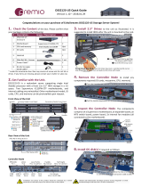
Figure 1-4. Motherboard Layout
1.5 Motherboard Layout
the table on the following page for descriptions. For detailed descriptions, pinout information
JTPM1
SAN MAC
SAS CODE
PRESS FIT
JPWR3
JSD2
JSD1
JBT1
JNVI2C1
JRK1
MH11
MH10
JSTBY1
BT1
+
LEDS1
JD1
JP2
JP3
I-SGPIO1
S-SGPIO1
I-SGPIO2
I-SATA3
I-SATA2
I-SATA1
I-SATA0
S-SATA1
S-SATA0
JPWR2
JPWR1
SXB2
IPMI CODE
FAN6
FAN7
FAN5
FAN3
FAN4
FAN2
FAN1
LE2
LEDM1
LE3
LE1
JP4
JPSAS1
JPS1
JP1
JPG1
JWD1
JPME2
JPTG1
JOH1
JF1
JPI2C1
BIOS LICENSE
DESIGNED IN USA
MAC CODE
X11SPW-CTF
REV:1.02
BAR CODE
M.2 PCI-E 3.0 X4
USB6
USB4/5
SXB1C
SXB1B
SXB1A
USB10/11(3.0)
JIPMB1
USB7/8(3.0)
USB9(3.0)
USB2/3
COM2
I-SATA 4-7
LAN2
VGA
CPU
LAN1
DIMMB1
LEDLED12LEDFAIL
ON
DIMMA1
NMIXPWRHDDNICNICUIDPSRSTPWR
DIMMF1
DIMME1
DIMMD1
DIMMC1
IPMI_LAN
USB0/1
COM1
SP1
Intel
C622
ASpeed
AST2500
Intel
X557
JUIDB1
JL1
L-SAS0-3
IPMI_LAN
USB0/1
LAN1
USB7/8 (3.0)
LAN2
COM1
VGA
JUIDB1
LE1
JPTG1
JTPM1
COM2
JPWR2
JPWR1
JF1
JPI
2
C1
FAN2 FAN1
LE3
FAN5 FAN4
USB10/11 (3.0)
USB4/5
USB6
FAN6
DIMMA1
DIMMD1
DIMMC1
DIMMB1
SP1
JWD1
JSTBY1
BT1
JBT1
S-SATA0
S-SATA1
JSD1
I-SGPIO1
I-SGPIO2
JPWR3
JIMPB1
MH11
JPG1
LEDM1
I-SATA3
SXB1C
JL1
FAN3
LE2
JD1
JOH1
FAN7
S-SGPIO1
JRK1
JSD2
I-SATA2
I-SATA0
I-SATA1
I-SATA4-7
USB2/3
JPS1
JPSAS1
L-SAS0-3
MH10
LEDS1
USB9 (3.0)
SXB1B
SXB1A
SXB2
DIMME1
DIMMF1
M.2
JNVI
2
C1
JPME2
CPU
1
4 4
3
2
14 4
3
2
1
5019P-WT
5019P-WTR

1514
SuperServer 5019P-WT/WTR User's Manual Chapter 1: Introduction
Quick Reference Table
Jumper Description Default Setting
JBT1 CMOS Clear Open (Normal)
JPG1 VGA Enable/Disable Pins 1-2 (Enabled)
JPME2 ME Manufacturing Mode Pins 1-2 (Normal)
JPS1 SAS 3.0 Enable/Disable Pins 1-2 (Enabled)
JPSAS1 SAS HDD Enable/Disable Pins 1-2 (Enabled)
JPTG1 LAN Enable/Disable Pins 1-2 (Enabled)
JWD1 Watch Dog Timer Pins 1-2 (Reset)
LED Description Status
LE1
LE2 Onboard Power LED Solid Green: Power On
LE3 M.2 LED Blinking Green: Device Working
LEDM1 BMC Heartbeat LED Blinking Green: BMC Normal
LEDS1 SAS Activity LED
Blinking Green: SAS Active
Solid Red: SAS Error
Connector Description
BT1 Onboard Battery
COM1, COM2 COM Port, COM Header
FAN1 ~ FAN7 System Fan Headers
IPMI_LAN Dedicated IPMI LAN Port
I-SATA0~7 Intel® PCH SATA 3.0 Ports (with RAID 0, 1, 5, 10)
I-SGPIO1, I-SGPIO2, S-SGPIO1 Serial Link General Purpose I/O Headers
JD1 Speaker/Power LED Indicator (Pins 1-3: Power LED, Pins 4-7: Speaker)
JF1 Front Control Panel Header
JIPMB1 4-pin BMC External I
2
C Header (for an IPMI card)
JL1 Chassis Intrusion Header
JNVI
2
C1 NVMe I
2
C Header
JOH1 Overheat LED Header
JPI
2
C1 Power System Management Bus (SMB) I
2
C Header
JPWR1 8-pin 12V DC Power Connector for CPU (Required)
JPWR2 24-pin ATX Power Connector
JPWR3 4-pin 12V Power Connector for GPU Card (Requires an extra 12V power at up to 75W)
JRK1 Intel RAID Key Header
JSD1, JSD2 SATA DOM Power Connectors
JSTBY1 Standby Power Header
JTPM1 Trusted Platform Module (TPM)/Port 80 Connector
JUIDB1
Connector Description
LAN1, LAN2 10GbE LAN Ports
L-SAS0~3 Four SAS 3.0 Ports (with RAID 0, 1, 10) (X11SPW-CTF only)
M.2 M.2 PCI-E 3.0 X4 or SATA 3.0 Slot
MH10, MH11 M.2 Mounting Holes
SP1 Internal Speaker/Buzzer
S-SATA0~1 SATA 3.0 Ports with SATA DOM Power
SXB1A, SXB1B, SXB1C Supermicro Proprietary WIO Left Add-on Card Slots
SXB2 Supermicro Proprietary WIO Right Add-on Card Slot
USB0/1 Back Panel Universal Serial Bus (USB) 2.0 Ports
USB2/3, USB4/5 Front Accessible USB 2.0 Headers
USB6 USB 2.0 Header (Not customized for the front panel)
USB7/8 Back Panel USB 3.0 Ports
USB9 USB 3.0 Type-A Header
USB10/11 Front Accessible USB 3.0 Header
VGA VGA Port

16
SuperServer 5019P-WT/WTR User's Manual
Figure 1-5. Intel PCH C622 Chipset: System Block Diagram
Note: This is a general block diagram and may not exactly represent the features on your
motherboard.
SPI
LAN3
RGRMII
FRONT PANEL
SYSTEM POWER
CTRL
FAN SPEED
PCI-E X1 G2
USB 2.0
#6 USB2.0
SFI
PCH
C622
USB 2.0
USB
RTL8211E-VB-CG
RJ45
ESPI
Temp Sensor
EMC1402-1 *2 at diff SMBUS
USB 3.0
USB
SPI
AST2500
BMC
#8~11
#5
COM1
Connector
COM2
Header
VGA CONN
BMC Boot Flash
DDR4
SXB2
5+1 PHASE
205W
2133/2666
DDRIV
VR13
#C-1
#B-1
#A-1
SXB1
PCI-E X8 G3
PCI-E X16 G3
DMI3
SNB CORE
DDR-IV
#3 #1B
VCCP0 12v
VCCP0
PECI:30
SOCKET ID:0
#1A
ESPI
Header
C622 X8 UPLINK
NO QAT 2*10G+2*1G(~17W)
2133/2666
DDRIV
#F-1
#E-1
#D-1
PCI-E X8
Uplink
PCI-E X16
#2
Front USB2.0 x 4
USB 2.0
USB
Rear USB2.0 x 2
USB2.0 #2,3
USB2.0 #4,5
USB2.0 #0,1
Front USB3.0 x 2
USB
USB
Type A USB3.0
Rear USB3.0 x 2
X557 (10G)
Intel
RMII/NCSI
SFI
M.2 SSD
PCI-E X4 G3
6.0 Gb/S
#1
#0
sSATA
SATA-DOM
6.0 Gb/S
#1
#0
SATA
#3
#2
#4
#5
#6
#7
Debug Card
TPM HEADER
BIOS
Switch
SPI
SPI
PCI-E X16
PCI-E X16 G3
RJ45
RJ45
#0~3
DMI3
PCI-E X8
LAN1
LAN2

Chapter 2: Server Installation
17
Chapter 2
Server Installation
2.1 Overview
This chapter provides advice and instructions for mounting your system in a server rack.
If your system is not already fully integrated with processors, system memory etc., refer to
Caution: Electrostatic Discharge (ESD) can damage electronic components. To prevent such
damage to PCBs (printed circuit boards), it is important to use a grounded wrist strap, handle
all PCBs by their edges and keep them in anti-static bags when not in use.
2.2 Preparing for Setup
The box in which the system was shipped should include the rackmount hardware needed to
install it into the rack. Please read this section in its entirety before you begin the installation.
Choosing a Setup Location
•
The system should be situated in a clean, dust-free area that is well ventilated. Avoid areas
• Leave enough clearance in front of the rack so that you can open the front door completely
(~25 inches) and approximately 30 inches of clearance in the back of the rack to allow
• This product should be installed only in a Restricted Access Location (dedicated equipment
rooms, service closets, etc.).
• This product is not suitable for use with visual display workplace devices acccording to §2
of the German Ordinance for Work with Visual Display Units.
Rack Precautions
•
the full weight of the rack rests on them.
• In single rack installations, stabilizers should be attached to the rack. In multiple rack in-
stallations, the racks should be coupled together.

SuperServer 5019P-WT/WTR User's Manual Chapter 2: Server Installation
1918
Circuit Overloading
Consideration should be given to the connection of the equipment to the power supply circuitry
and the effect that any possible overloading of circuits might have on overcurrent protection
and power supply wiring. Appropriate consideration of equipment nameplate ratings should
be used when addressing this concern.
Reliable Ground
A reliable ground must be maintained at all times. To ensure this, the rack itself should be
grounded. Particular attention should be given to power supply connections other than the
direct connections to the branch circuit (i.e. the use of power strips, etc.).
special precautions to ensure that the system remains stable. The following guidelines
are provided to ensure your safety:
• This unit should be mounted at the bottom of the rack if it is the only unit in the rack.
•
with the heaviest component at the bottom of the rack.
• If the rack is provided with stabilizing devices, install the stabilizers before mounting or
servicing the unit in the rack.
• Always make sure the rack is stable before extending a server or other component from
the rack.
• You should extend only one server or component at a time - extending two or more simul-
taneously may cause the rack to become unstable.
Server Precautions
• Review the electrical and general safety precautions in Appendix B.
• Determine the placement of each component in the rack before you install the rails.
•
way up.
• Use a regulating uninterruptible power supply (UPS) to protect the server from power
surges and voltage spikes and to keep your system operating in case of a power failure.
• Allow any drives and power supply modules to cool before touching them.
• When not servicing, always keep the front door of the rack and all covers/panels on the
servers closed to maintain proper cooling.
Rack Mounting Considerations
Ambient Operating Temperature
If installed in a closed or multi-unit rack assembly, the ambient operating temperature of
the rack environment may be greater than the room's ambient temperature. Therefore,
consideration should be given to installing the equipment in an environment compatible with
the manufacturer’s maximum rated ambient temperature (TMRA).
Airow
operation is not compromised.
Mechanical Loading
Equipment should be mounted into a rack so that a hazardous condition does not arise due
to uneven mechanical loading.

SuperServer 5019P-WT/WTR User's Manual Chapter 2: Server Installation
2120
Installing the Outer Rails
Begin by measuring the distance from the front rail to the rear rail of the rack. Attach a short
bracket to the front side of the right outer rail and a long bracket to the rear side of the right
screws and the long bracket to the rear side of the outer rail with three screws. Repeat these
steps for the left outer rail.
Locking Tabs:
is to lock the server into place when installed and pushed fully into the rack, which is its
normal position. Secondly, these tabs also lock the server in place when fully extended from
the rack. This prevents the server from coming completely out of the rack when you pull it
out for servicing.
Note:
server into place when installed and pushed fully into the rack, which is its normal position.
Secondly, these tabs also lock the server in place when fully extended from the rack. This
prevents the server from coming completely out of the rack when you pull it out for servicing.
Figure 2-2. Installing the Rails
Warning: Stability hazard. The rack stabilizing mechanism must be in place, or the
stabilize the rack can cause the rack to tip over.
2.3 Installing the Rails
There are a variety of rack units on the market, which may require a slightly different assembly
procedure.
The following is a basic guideline for installing the system into a rack with the rack mounting
hardware provided. You should also refer to the installation instructions that came with the
Identifying the Sections of the Rack Rails
You should have received two rack rail assemblies in the rack mounting kit. Each assembly
of short brackets to be used on the front side of the outer rails are also included.
Installing the Inner Rails
Both the left and right side inner rails have been pre-attached to the chassis. Proceed to the
next step.
Warning: do not pick up the server with the front handles. They are designed to pull
the system from a rack only.
Figure 2-1. Identifying the Sections of the Rack Rails
(right side rail shown)

SuperServer 5019P-WT/WTR User's Manual Chapter 2: Server Installation
2322
Note:
Installing to a Telco Rack
To install the SuperServer 5019P-WT/WTR into a Telco (or “open”) type rack, use two
L-shaped brackets on either side of the chassis (four total).
1. First, determine how far the server will extend out from the front of the rack. The chassis
should be positioned so that the weight is balanced between front and back.
2. Attach the two front brackets to each side of the chassis, then the two rear brackets
3. Finish by sliding the chassis into the rack and tightening the brackets to the rack. See
Figure 2-4.
Figure 2-4. Installing the Server into a Telco Rack
Figure 2-3. Installing the Server into a Rack
Note:
2.4 Installing the Server into a Rack
Installing to a Standard Rack
You should now have rails attached to both the chassis and the rack. The next step is to
install the server into the rack.
1. Line up the rear of the chassis rails with the front of the rack rails.
2. Slide the chassis rails into the rack rails, keeping the pressure even on both sides (you
may have to press the locking tabs when inserting). See Figure 2-3.
3. When the server has been pushed completely into the rack, you should hear the locking
tabs "click".
Slide rail mounted equipment is not to be used as a shelf or a work space.

SuperServer 5019P-WT/WTR User's Manual
2524
Chapter 3: Maintenance and Component Installation
Chapter 3
Maintenance and Component Installation
This chapter provides instructions on installing and replacing main system components. To
numbers given.
system. Please follow the procedures given in each section.
3.1 Removing Power
Use the following procedure to ensure that power has been removed from the system. This
step is necessary when removing or installing non hot-swap components or when replacing
a non-redundant power supply.
1. Use the operating system to power down the system.
2. After the system has completely shut-down, disconnect the AC power cord(s) from the
power strip or outlet. (If your system has more than one power supply, remove the AC
power cords from all power supply modules.)
3. Disconnect the power cord(s) from the power supply module(s).
3.2 Accessing the System
The 815TQC-605WB/R504WB features a removable top cover, which allows easy access to
the inside of the chassis.
Removing the Top Cover
1. Begin by removing power from the system as described in Section 3.1.
2. Remove the screws securing the cover to the chassis.
3. Slide the cover toward the rear of the chassis. See Figure 3-1.
4. Lift the cover from the chassis.
Warning: Except for short periods of time, do not operate the server without the cover in place.
3.3 Motherboard Components
Processor and Heatsink Installation
Warning: When handling the processor package, avoid placing direct pressure on the label
area of the CPU or CPU socket. Also, improper CPU installation or socket misalignment can
cause serious damage to the CPU or motherboard which may result in RMA repairs. Please
read and follow all instructions thoroughly before installing your CPU and heatsink.
Follow the procedures in this section to install a processor (CPU) and heatsink to the
motherboard.
Notes:
•
chapter before handling, installing, or removing system components.
• Always connect the power cord last, and always remove it before adding, removing, or
changing any hardware components. Please note that the processor and heatsink should
the entire PHM into the CPU socket.
• When you receive a motherboard without a processor pre-installed, make sure that the
plastic CPU socket cap is in place and that none of the socket pins are bent; otherwise,
contact your retailer immediately.
•
heatsink only.
• Refer to the Supermicro website for updates on CPU support.
The Intel Xeon 81xx/61xx/51xx/41xx/31xxSeries Processor
Note: All graphics, drawings, and pictures shown in this manual are for illustration only.
The components that came with your machine may or may not look exactly the same
as those shown in this manual.
SKX Processor

SuperServer 5019P-WT/WTR User's Manual
2726
Chapter 3: Maintenance and Component Installation
Overview of the Processor Socket Assembly
The processor socket assembly contains 1) the Intel SKX processor, 2) the processor clip,
3) the dust cover, and 4) the CPU socket.
3. Dust Cover
4. CPU Socket
1. SKX Processor
Note: Be sure to cover the CPU socket with the dust cover when the CPU is not in-
stalled.
2. Processor Clip (the plastic processor
package carrier used for the CPU)
Overview of the Processor Heatsink Module (PHM)
The Processor Heatsink Module (PHM) contains 1) a heatsink, 2) a processor clip, and 3)
the SKX processor.
1. Heatsink
2. Processor Clip
3. SKX Processor
Processor Heatsink Module (PHM)
(Bottom View for a non-F Model)

SuperServer 5019P-WT/WTR User's Manual
2928
Chapter 3: Maintenance and Component Installation
Attaching the Non-F Model Processor to the Processor Clip to
Create the Processor Carrier Assembly
To properly install the CPU into the processor clip, please follow the steps below:
1. Locate pin 1 (notch A), which is the triangle located on the top of the processor clip.
Also locate notch B and notch C on the processor clip.
2. Locate pin 1 (notch A), which is the triangle on the substrate of the CPU. Also, locate
notch B and notch C on the CPU as shown below.
3. Align pin 1 (the triangle on the substrate) of the CPU with pin 1 (the triangle) of the
processor clip. Once they are aligned, carefully insert the CPU into the processor clip by
sliding notch B of the CPU into notch B of the processor clip, and sliding notch C of the
CPU into notch C of the processor clip.
4. Examine all corners of the CPU to ensure that it is properly seated on the processor
clip. Once the CPU is securely attached to the processor clip, the processor carrier
assembly is created.
Note: Please exercise extreme caution when handling the CPU. Do not touch the CPU
LGA-lands to avoid damaging the LGA-lands or the CPU. Be sure to wear ESD gloves when
handling components.
Processor Carrier Assembly (with CPU
mounted on the Processor Clip)
A
B
C
Allow Notch C to
latch on to CPU
Allow Notch B to
latch on to CPU
A
A
B
B
C
C
Pin 1
Align CPU Pin 1
CPU (Upside Down)
w/CPU LGA Lands up
CPU/Heatsink Package
(Upside Down)
Align Notch C of the CPU
and Notch C of the Processor Clip
Align Notch B of the CPU
and Notch B of the Processor Clip
Attaching the Non-F Model Processor Carrier Assembly to the
Heatsink to Form the Processor Heatsink Module (PHM)
After you have made a processor carrier assembly by following the instructions on the
previous page, please follow the steps below to mount the processor carrier assembly onto
the heatsink to create the Processor Heatsink Module (PHM):
1. Locate "1" on the heatsink label and the triangular corner next to it on the heatsink.
and turn the heatsink upside down with the thermal-grease side facing up. Remove the
as needed. (Skip this step if you have a new heatsink because the necessary thermal
grease is pre-applied in the factory.)
2. Holding the processor carrier assembly at the center edge, turn it upside down. With
the thermal-grease side facing up, locate the hollow triangle located at the corner of the
processor carrier assembly ("a" in the graphic). Note a larger hole and plastic mounting
clicks located next to the hollow triangle. Also locate another set of mounting clicks and
a larger hole at the diagonal corner of the same (reverse) side of the processor carrier
assembly ("b" in the graphic).
Heatsink
(Upside Down)
Non-Fabric CPU and Processor Clip
(Upside Down)
C
D
d
c
a
b
A
B
On Locations of (C, D), the notches
snap onto the heat sink’s
mounting holes
On Locations (A, B), the notches
snap onto the heatsink’s sides
A
B
D
C
Make sure Mounting
Notches snap into place
Triangle on the CPU
Triangle on the
Processor Clip
3. With the back of the heatsink
and the reverse side of the
processor carrier assembly facing
up, align the triangular corner on
the heatsink ("A" in the graphic)
against the mounting clips next
to the hollow triangle ("a") on the
processor carrier assembly.
4. Also align the triangular corner ("B")
at the diagonal side of the heatsink
with the corresponding clips on the
processor carrier assembly ("b").
5. Once the mounting clips on
the processor carrier assembly
are properly aligned with the
corresponding holes on the back
of the heatsink, securely attach the
heatsink to the processor carrier
assembly by snapping the mounting
clips at the proper places on the
heatsink to create the processor
heatsink module (PHM).

SuperServer 5019P-WT/WTR User's Manual
3130
Chapter 3: Maintenance and Component Installation
Preparing the CPU Socket for Installation
This motherboard comes with the CPU socket pre-assembled in the factory. The CPU socket
contains 1) a dust cover, 2) a socket bracket, 3) the CPU (P0) socket, and 4) a back plate.
These components are pre-installed on the motherboard before shipping.
CPU Socket w/Dust Cover On
Removing the Dust Cover from the CPU Socket
Remove the dust cover from the CPU socket, exposing the SKX socket and socket pins as
shown on the illustration below.
Note: Do not touch the socket pins to avoid damaging them, causing the CPU to malfunction.
Dusk Cover
SKX CPU Socket
Socket Pins
Remove the dust cover from
the CPU socket. Do not
touch the socket pins!
Installing the Processor Heatsink Module (PHM)
Once you have assembled the processor heatsink module (PHM) by following the instructions
listed on page 26, you are ready to install the processor heatsink module (PHM) into the CPU
socket on the motherboard. To install the PHM into the CPU socket, follow the instructions
below:
1. Locate the triangle (pin 1) on the CPU socket, and locate the triangle (pin 1) at the
turn the PHM upside down. With the LGA-lands side facing up, you will note the hollow
triangle located next to a screw at the corner. Turn the PHM right side up, and you will
see a triangle marked on the processor clip at the same corner of hollow triangle.)
2. Carefully align pin 1 (the triangle) on the the PHM against pin 1 (the triangle) on the
CPU socket.
3. Once they are properly aligned, insert the two diagonal oval holes on the heatsink into
the guiding posts.
4. Using a T30 Torx-bit screwdriver, install four screws into the mounting holes on the
socket to securely attach the PHM onto the motherboard starting with the screw marked
"1" (in the sequence of 1, 2, 3, and 4).
Note: Do not use excessive force when tightening the screws to avoid damaging the LGA-
lands and the processor.
#1
#2
#3
#4
Small Guiding Post
Large Guiding Post
Oval D
T30 Torx Driver
Use a torque
of 12 lbf
Oval C
Printed Triangle
Mounting the Processor Heatsink Module
into the CPU socket (on the motherboard)
Tighten the screws in the
sequence of 1, 2, 3, 4 (top 3 quarter view)

SuperServer 5019P-WT/WTR User's Manual
3332
Chapter 3: Maintenance and Component Installation
Printed Triangle on Motherboard
Removing the screws in
the sequence of 4, 3, 2, 1
#1
#2
#3
#4
After removing the screws,
lift the Processor Heatsink
Module off the CPU socket.
CPU Socket
Removing the Processor Heatsink Module (PHM) from the
Motherboard
Before removing the processor heatsink module (PHM), unplug the power cord from the
power outlet.
1. Using a T30 Torx-bit screwdriver, turn the screws on the PHM counterclockwise to
loosen them from the socket, starting with the screw marked #4 (in the sequence of 4,
3, 2, 1).
2. After all four screws are removed, wiggle the PHM gently and pull it up to remove it
from the socket.
Note: To properly remove the processor heatsink module, be sure to loosen and remove the
screws on the PHM in the sequence of 4, 3, 2, 1 as shown below.
Memory Installation
Memory Support
The X11SPW-TF supports up to 192 GB of RDIMM, 384 GB of LRDIMM, and 768 GB of 3DS
LRDIMM DDR4 (288-pin) ECC memory with speeds of up to 2666 MHz in six (6) memory
slots.
Note: Check the Supermicro website for possible updates to memory support.
Important: Exercise extreme care when installing or removing DIMM modules to prevent any
possible damage.
Populating RDIMM/RDIMM 3DS/LRDIMM/LRDIMM 3DS DDR4 Memory Modules
Type
Ranks Per
DIMM and
Data Width
DIMM Capacity (GB)
Speed (MT/s); Voltage (V); Slots per Channel
(SPC) and DIMMs per Channel (DPC)
1 Slot per
Channel
2 Slots per Channel
DRAM Density 1 DPC 1 DPC 2 DPC
4 GB 8 GB 1.2 V 1.2 V 1.2 V
RDIMM SRx4 8 GB 16 GB 2666 2666 2666
RDIMM SRx8 4 GB 8 GB 2666 2666 2666
RDIMM DRx8 8 GB 16 GB 2666 2666 2666
RDIMM DRx4 16 GB 32 GB 2666 2666 2666
RDIMM 3DS
QRx4 NA 2H-64 GB 2666 2666 2666
8Rx4 NA 4H-128 GB 2666 2666 2666
LRDIMM QRx4 32 GB 64 GB 2666 2666 2666
LRDIMM 3DS
QRx4 NA 2H-64 GB 2666 2666 2666
8Rx1 NA 4H-128 GB 2666 2666 2666
Note: Visit the product page on the Supermicro website for possible updates to memory
support (www.supermicro.com).

SuperServer 5019P-WT/WTR User's Manual
3534
Chapter 3: Maintenance and Component Installation
DIMM Module Population Sequence
When installing memory modules, the DIMM slots must be populated in the following order:
DIMMA1, DIMMD1, DIMMB1, DIMME1, DIMMC1, DIMMF1.
• Always use DDR4 memory of the same type, size and speed.
• Mixed DIMM speeds can be installed. However, all DIMMs will run at the speed of the
slowest DIMM.
• The motherboard will support odd-numbered modules (1 or 3 modules installed). However,
to achieve the best memory performance, a balanced memory population is recommended.
DIMM Installation
1. Insert the desired number of DIMMs
into the memory slots in the following
order: DIMMA1, DIMMD1, DIMMB1,
DIMME1, DIMMC1, DIMMF1. For the best
performance, please use the memory
modules of the same type and speed.
2. Push the release tabs outwards on both
ends of the DIMM slot to unlock it.
3. Align the key of the DIMM module with the
receptive point on the memory slot.
4. Align the notches on both ends of the
module against the receptive points on the
ends of the slot.
5. Press the notches on both ends of the
module straight down into the slot until the
module snaps into place.
6. Press the release tabs to the lock positions
to secure the DIMM module into the slot.
DIMM Removal
Press both release tabs on the ends of the
DIMM module to unlock it. Once the DIMM
module is loosened, remove it from the
memory slot.
Release Tabs
Notches
Press both notches
straight down into
the memory slot.
JTPM1
SAN MAC
SAS CODE
PRESS FIT
JPWR3
JSD2
JSD1
JBT1
JNVI2C1
JRK1
MH11
MH10
JSTBY1
BT1
+
LEDS1
JD1
JP2
JP3
I-SGPIO1
S-SGPIO1
I-SGPIO2
I-SATA3
I-SATA2
I-SATA1
I-SATA0
S-SATA1
S-SATA0
JPWR2
JPWR1
SXB2
IPMI CODE
FAN6
FAN7
FAN5
FAN3
FAN4
FAN2
FAN1
LE2
LEDM1
LE3
LE1
JP4
JPSAS1
JPS1
JP1
JPG1
JWD1
JPME2
JPTG1
JOH1
JF1
JPI2C1
BIOS LICENSE
DESIGNED IN USA
MAC CODE
X11SPW-CTF
REV:1.02
BAR CODE
M.2 PCI-E 3.0 X4
USB6
USB4/5
SXB1C
SXB1B
SXB1A
USB10/11(3.0)
JIPMB1
USB7/8(3.0)
USB9(3.0)
USB2/3
COM2
I-SATA 4-7
LAN2
VGA
CPU
LAN1
DIMMB1
LEDLED12LEDFAIL
ON
DIMMA1
NMIXPWRHDDNICNICUIDPSRSTPWR
DIMMF1
DIMME1
DIMMD1
DIMMC1
IPMI_LAN
USB0/1
COM1
SP1
Intel
C622
ASpeed
AST2500
Intel
X557
JUIDB1
JL1
L-SAS0-3
DIMME1
DIMMC1
DIMMA1
DIMMB1
DIMMD1
DIMMF1

SuperServer 5019P-WT/WTR User's Manual
3736
Chapter 3: Maintenance and Component Installation
Figure 3-1. Removing the Riser Bracket
Figure 3-2. Installing Expansion Cards
PCI Expansion Card Installation
The system includes two pre-installed riser cards (p/n CSE-RR1U-E8 and RSC-R1UW-2E16)
chassis.
Installing PCI Expansion Cards
The riser cards are already pre-installed into the motherboard. Perform the following steps
to install an add-on card if needed:
1. Remove the riser card bracket from the chassis by unscrewing only those screws
indicated by the screwdriver icon as illustrated in Figure 3-1.
2. Lift the riser card bracket from the chassis.
3. Install the riser card on the bracket using the two screws provided.
4. Open the latch on the end of the bracket.
5. Install the expansion card by sliding the card into the appropriate slot in the riser card,
and then close the bracket latch over the end of it.
6. Install the entire assembly into the appropriate slot on the serverboard while aligning the
bracket in the rear of the chassis.
Note:
only. The serverboard may differ from that found in the 5019P-WT/WTR.
/