Page is loading ...

1.16-03222018-144100
USER MANUAL
EPIA-M860
Mini-ITX embedded board

Tested To Comply
With FCC Standards
FOR HOME OR OFFICE USE
Copyright
Copyright © 2016 VIA Technologies Incorporated. All rights reserved.
No part of this document may be reproduced, transmitted, transcribed, stored in a retrieval system, or translated into any language, in any form or by
any means, electronic, mechanical, magnetic, optical, chemical, manual or otherwise without the prior written permission of VIA Technologies,
Incorporated.
Trademarks
All trademarks are the property of their respective holders.
Disclaimer
No license is granted, implied or otherwise, under any patent or patent rights of VIA Technologies. VIA Technologies makes no warranties, implied or
otherwise, in regard to this document and to the products described in this document. The information provided in this document is believed to be
accurate and reliable as of the publication date of this document. However, VIA Technologies assumes no responsibility for the use or misuse of the
information (including use or connection of extra device/equipment/add-on card) in this document and for any patent infringements that may arise
from the use of this document. The information and product specifications within this document are subject to change at any time, without notice and
without obligation to notify any person of such change.
VIA Technologies, Inc. reserves the right the make changes to the products described in this manual at any time without prior notice.
Regulatory Compliance
FCC-A Radio Frequency Interference Statement
This equipment has been tested and found to comply with the limits for a class A digital device, pursuant to part 15 of the FCC rules. These limits are
designed to provide reasonable protection against harmful interference when the equipment is operated in a commercial environment. This
equipment generates, uses, and can radiate radio frequency energy and, if not installed and used in accordance with the instruction manual, may cause
harmful interference to radio communications. Operation of this equipment in a residential area is likely to cause harmful interference, in which case
the user will be required to correct the interference at his personal expense.
Notice 1
The changes or modifications not expressly approved by the party responsible for compliance could void the user's authority to operate the
equipment.
Notice 2
Shielded interface cables and A.C. power cord, if any, must be used in order to comply with the emission limits.
Notice 3
The product described in this document is designed for general use, VIA Technologies assumes no responsibility for the conflicts or damages arising
from incompatibility of the product. Check compatibility issue with your local sales representatives before placing an order.

Battery Recycling and Disposal
Only use the appropriate battery specified for this product.
Do not re-use, recharge, or reheat an old battery.
Do not attempt to force open the battery.
Do not discard used batteries with regular trash.
Discard used batteries according to local regulations.
Safety Precautions
Always read the safety instructions carefully.
Keep this User's Manual for future reference.
All cautions and warnings on the equipment should be noted.
Keep this equipment away from humidity.
Lay this equipment on a reliable flat surface before setting it up.
Make sure the voltage of the power source and adjust properly 110/220V before connecting the equipment to the
power inlet.
Place the power cord in such a way that people cannot step on it.
Always unplug the power cord before inserting any add-on card or module.
If any of the following situations arises, get the equipment checked by authorized service personnel:
The power cord or plug is damaged.
Liquid has penetrated into the equipment.
The equipment has been exposed to moisture.
The equipment has not worked well or you cannot get it work according to User's Manual.
The equipment has dropped and damaged.
The equipment has obvious sign of breakage.
Do not leave this equipment in an environment unconditioned or in a storage temperature above 60°C (140°F). The
equipment may be damaged.
Do not leave this equipment in direct sunlight.
Never pour any liquid into the opening. Liquid can cause damage or electrical shock.
Do not place anything over the power cord.
Do not cover the ventilation holes. The openings on the enclosure protect the equipment from overheating.

EPIA-M860 User Manual
iv
Box Contents and Ordering Information
EPIA-M860-12E (ATX version)
1 x EPIA-M860 embedded board
1 x I/O bracket
1 x SATA cable
EPIA-M860-12PE (DC-in version)
1 x EPIA-M860 embedded board
1 x I/O bracket
1 x SATA cable
1 x SATA power cable
1 x AC/DC adapter (optional)

EPIA-M860 User Manual
v
Table of Contents
1.
Product Overview .......................................................................................................................................................................... 1
1.1.
Key Features and Benefits ........................................................................................................................................................ 1
1.1.1.
VIA Nano™ 1.2GHz Processor .......................................................................................................................................... 1
1.1.2.
VIA VX900 Chipset .............................................................................................................................................................. 1
1.1.3.
Flexible Power Options ..................................................................................................................................................... 1
1.1.4.
Modular Expansion Options .............................................................................................................................................. 1
1.2.
Product Specifications .............................................................................................................................................................. 2
1.3.
Layout Diagram .......................................................................................................................................................................... 5
1.4.
Product Dimensions .................................................................................................................................................................. 6
1.5.
Height Distribution .................................................................................................................................................................... 7
2.
I/O Interface .................................................................................................................................................................................... 8
2.1.
External I/O Ports ...................................................................................................................................................................... 8
2.1.1.
HDMI
®
Port ............................................................................................................................................................................ 9
2.1.2.
VGA Port .............................................................................................................................................................................. 10
2.1.3.
COM Port ............................................................................................................................................................................. 11
2.1.4.
USB Ports ............................................................................................................................................................................. 11
2.1.5.
Gigabit Ethernet Port ......................................................................................................................................................... 12
2.1.6.
Audio Ports .......................................................................................................................................................................... 13
2.1.7.
DC-in Jack ............................................................................................................................................................................ 13
2.2.
Onboard Connectors ............................................................................................................................................................. 14
2.2.1.
ATX Power Connector ...................................................................................................................................................... 14
2.2.2.
DC-in Power Connector ................................................................................................................................................... 15
2.2.3.
SATA Power Connector ................................................................................................................................................... 16
2.2.4.
CMOS Battery Slot ............................................................................................................................................................. 17
2.2.5.
Front Panel Pin Header ..................................................................................................................................................... 18
2.2.6.
SMBus Pin Header .............................................................................................................................................................. 18
2.2.7.
Thermal Resistor Pin Header ........................................................................................................................................... 19
2.2.8.
Fan Connectors ................................................................................................................................................................... 19
2.2.9.
SATA Connectors .............................................................................................................................................................. 20
2.2.10.
USB Pin Headers ................................................................................................................................................................. 21
2.2.11.
COM Pin Headers .............................................................................................................................................................. 22
2.2.12.
PS/2 Keyboard and Mouse Pin Header ......................................................................................................................... 23
2.2.13.
Front Audio Pin Header .................................................................................................................................................... 24
2.2.14.
Digital I/O Pin Header ....................................................................................................................................................... 25
2.2.15.
SPI Pin Header .................................................................................................................................................................... 26
3.
Jumpers and Switches ................................................................................................................................................................ 27
3.1.
AT/ATX Mode .......................................................................................................................................................................... 27
3.2.
SATA DOM Power Select Jumper ...................................................................................................................................... 28
3.3.
Clear CMOS Jumper ............................................................................................................................................................... 29
3.4.
COM Voltage Select Jumpers .............................................................................................................................................. 30
3.4.1.
COM2 Voltage Select Jumper ........................................................................................................................................ 30
3.4.2.
COM3 and COM4 Voltage Select Jumper .................................................................................................................. 31
3.4.3.
COM5 and COM6 Voltage Select Jumper .................................................................................................................. 31
4.
Expansion Slots ........................................................................................................................................................................... 32

EPIA-M860 User Manual
vi
4.1.
DDR3 Memory Slot ................................................................................................................................................................. 32
4.1.1.
Installing a Memory Module ........................................................................................................................................... 33
4.1.2.
Removing a Memory Module .......................................................................................................................................... 34
4.2.
Mini PCIe Slot ........................................................................................................................................................................... 35
4.3.
PCI Express Slot ....................................................................................................................................................................... 36
4.4.
PCI Slot ...................................................................................................................................................................................... 37
5.
Hardware Installation ................................................................................................................................................................. 38
5.1.
Installing into a Chassis .......................................................................................................................................................... 38
5.1.1.
Suggested minimum chassis dimensions ...................................................................................................................... 38
5.1.2.
Suggested minimum chassis height................................................................................................................................ 39
5.1.3.
Suggested keepout areas ................................................................................................................................................. 40
6.
BIOS Setup Utility ....................................................................................................................................................................... 41
6.1.
Entering the BIOS Setup Utility ............................................................................................................................................ 41
6.2.
Control Keys ............................................................................................................................................................................. 41
6.3.
Getting Help............................................................................................................................................................................. 41
6.4.
System Overview ..................................................................................................................................................................... 42
6.4.1.
AMIBIOS ............................................................................................................................................................................... 42
6.4.2.
Processor .............................................................................................................................................................................. 42
6.4.3.
System Memory .................................................................................................................................................................. 42
6.4.4.
System Time ........................................................................................................................................................................ 42
6.4.5.
System Date......................................................................................................................................................................... 42
6.5.
Advanced Settings .................................................................................................................................................................. 43
6.5.1.
CPU Configuration ............................................................................................................................................................. 44
6.5.1.1.
CPU Thermal Control ............................................................................................................................................. 44
6.5.2.
IDE Configuration ............................................................................................................................................................... 45
6.5.2.1.
Hard Disk Information ............................................................................................................................................. 45
6.5.3.
SuperIO Configuration ...................................................................................................................................................... 46
6.5.3.1.
Serial Ports 1 to 4 .................................................................................................................................................... 46
6.5.4.
Hardware Health Configuration ..................................................................................................................................... 47
6.5.5.
ACPI Configuration ............................................................................................................................................................ 48
6.5.5.1.
Suspend Mode ......................................................................................................................................................... 48
6.5.6.
APM Configuration ............................................................................................................................................................. 49
6.5.6.1.
Power Button Mode ................................................................................................................................................ 49
6.5.6.2.
Restore on AC/Power Loss .................................................................................................................................... 49
6.5.6.3.
Resume on PS/2 KBC ............................................................................................................................................... 49
6.5.6.4.
Wake-Up Key ............................................................................................................................................................ 50
6.5.6.5.
Wake-Up Password ................................................................................................................................................. 50
6.5.6.6.
Resume on PS/2 Mouse .......................................................................................................................................... 50
6.5.6.7.
Resume on Software RTC Alarm .......................................................................................................................... 50
6.5.6.8.
Resume on RTC Alarm ........................................................................................................................................... 50
6.5.6.9.
RTC Alarm Date (Days) .......................................................................................................................................... 50
6.5.6.10.
System Time .............................................................................................................................................................. 51
6.5.7.
Spread Spectrum Configuration ..................................................................................................................................... 52
6.5.7.1.
Spread Spectrum Setting ....................................................................................................................................... 52
6.5.8.
USB Configuration .............................................................................................................................................................. 53
6.5.8.1.
OnChip UHCI Device ............................................................................................................................................. 53
6.5.8.2.
OnChip EHCI Device .............................................................................................................................................. 53
6.5.8.3.
Legacy USB Support ............................................................................................................................................... 53

EPIA-M860 User Manual
vii
6.5.8.4.
USB 2.0 Controller Mode ...................................................................................................................................... 53
6.5.9.
CRB Configuration .............................................................................................................................................................. 54
6.5.9.1.
VT6130 LAN Control .............................................................................................................................................. 54
6.5.9.2.
LAN Option ROM ................................................................................................................................................... 54
6.6.
Advanced PCI/PnP Settings ................................................................................................................................................... 55
6.6.1.
Clear NVRAM...................................................................................................................................................................... 55
6.6.2.
Plug & Play O/S .................................................................................................................................................................. 55
6.6.3.
PCI Latency Timer............................................................................................................................................................... 55
6.6.4.
Allocate IRQ to PCI VGA ................................................................................................................................................. 55
6.6.5.
Palette Snooping ................................................................................................................................................................ 55
6.6.6.
PCI IDE BusMaster .............................................................................................................................................................. 56
6.6.7.
IRQ3~15 ............................................................................................................................................................................... 56
6.6.8.
DMA Channel 0~7 ............................................................................................................................................................. 56
6.6.9.
Reserved Memory Size...................................................................................................................................................... 56
6.6.10.
HotPlug Reserve I/O Port Size ........................................................................................................................................ 56
6.6.11.
HotPlug Reserve Memory Size ........................................................................................................................................ 56
6.6.12.
HotPlug Reserve PFMemory Size.................................................................................................................................... 56
6.7.
Boot Settings ............................................................................................................................................................................ 57
6.7.1.
Boot Settings Configuration ............................................................................................................................................. 57
6.7.1.1.
Quick Boot ................................................................................................................................................................ 57
6.7.1.2.
Quiet Boot................................................................................................................................................................. 57
6.7.1.3.
AddOn ROM Display Mode ................................................................................................................................. 57
6.7.1.4.
Bootup Num-Lock ................................................................................................................................................... 57
6.7.1.5.
PS/2 Mouse Support ............................................................................................................................................... 57
6.7.1.6.
Wait for ‘F1’ if Error ................................................................................................................................................. 58
6.7.1.7.
Hit ‘DEL’ Message Display ..................................................................................................................................... 58
6.7.1.8.
Interrupt 19 Capture ............................................................................................................................................... 58
6.8.
Security Settings ...................................................................................................................................................................... 59
6.8.1.
Change Supervisor Password .......................................................................................................................................... 59
6.8.2.
Password Check ................................................................................................................................................................. 60
6.9.
Advanced Chipset Settings ................................................................................................................................................... 61
6.9.1.
North Bridge VIA VX900 Configuration ........................................................................................................................ 61
6.9.1.1.
DRAM Clock/Timing Configuration ..................................................................................................................... 61
6.9.1.2.
AGP & P2P Bridge Configuration ......................................................................................................................... 62
6.9.1.3.
OnChip VGA Configuration .................................................................................................................................. 63
6.9.2.
South Bridge VIA VX900 Configuration ........................................................................................................................ 64
6.9.2.1.
SATA Gen2 Support ............................................................................................................................................... 64
6.9.2.2.
OnChip HDAC Device ........................................................................................................................................... 64
6.9.2.3.
Serial ATA Controller ............................................................................................................................................ 64
6.9.2.4.
HPET Support ........................................................................................................................................................... 64
6.9.2.5.
WATCHDOG Timer Enable .................................................................................................................................. 64
6.9.2.6.
WATCHDOG Timer RUN/STOP .......................................................................................................................... 64
6.9.2.7.
WATCHDOG Timer ACTION ............................................................................................................................... 64
6.9.2.8.
WATCHDOG Timer COUNT ................................................................................................................................ 64
6.9.2.9.
Keyboard/Mouse Wakeup Control ...................................................................................................................... 64
6.9.2.10.
PCI LAN S5 Wakeup ............................................................................................................................................... 65
6.9.2.11.
EuP/ErP Lot6 Support ............................................................................................................................................. 65
6.10.
Exit Options .............................................................................................................................................................................. 66
6.10.1.
Save Changes and Exit ...................................................................................................................................................... 66

EPIA-M860 User Manual
viii
6.10.2.
Discard Changes and Exit ................................................................................................................................................. 66
6.10.3.
Discard Changes ................................................................................................................................................................. 66
6.10.4.
Load Optimal Defaults ..................................................................................................................................................... 66
7.
Driver Installation ........................................................................................................................................................................ 67
7.1.
Microsoft Driver Support ....................................................................................................................................................... 67
7.2.
Linux Driver Support............................................................................................................................................................... 67
Appendix A. Power Consumption Report........................................................................................................................................ 68
A.1. EPIA-M860 ........................................................................................................................................................................................ 68
A.1.1. Playing DVDs (ATX) ................................................................................................................................................................ 68
A.1.2. Playing DVDs (DC-in) ............................................................................................................................................................. 68
A.1.3. Playing MP3s (ATX)................................................................................................................................................................. 68
A.1.4. Playing MP3s (DC-in) .............................................................................................................................................................. 69
A.1.5. Copying files on a network (ATX) ....................................................................................................................................... 69
A.1.6. Copying files on a network (DC-in) .................................................................................................................................... 69
A.1.7. Idle (ATX) ................................................................................................................................................................................. 69
A.1.8. Idle (DC-in) ............................................................................................................................................................................... 69
A.1.9. CCWINSTONE2004 (ATX) .................................................................................................................................................... 70
A.1.10. CCWINSTONE2004 (DC-in) ............................................................................................................................................... 70
A.1.11. S3 (ATX) .................................................................................................................................................................................. 70
A.1.12. S3 (DC-in) ............................................................................................................................................................................... 70
Appendix B. Riser Card Modules ...................................................................................................................................................... 71
B.1. PCIE-03 ............................................................................................................................................................................................... 71
B.2. EXT-PCI-01......................................................................................................................................................................................... 72
Appendix C. Mating Connector Vendor Lists .................................................................................................................................. 73

EPIA-M860 User Manual
ix
List of Tables
Table 1: HDMI
®
port pinout ........................................................................................................................................................................ 9
Table 2: VGA port pinout .......................................................................................................................................................................... 10
Table 3: COM port pinout ......................................................................................................................................................................... 11
Table 4: USB port pinout ............................................................................................................................................................................ 11
Table 5: Gigabit Ethernet port pinout ..................................................................................................................................................... 12
Table 6: Audio jack receptacle pinout .................................................................................................................................................... 13
Table 7: DC-in coaxial connector specifications .................................................................................................................................. 13
Table 8: ATX power connector pinout ................................................................................................................................................... 14
Table 9: DC-in power connector pinout ................................................................................................................................................ 15
Table 10: SATA power connector pinout .............................................................................................................................................. 16
Table 11: CMOS battery slot/connector pinout ................................................................................................................................... 17
Table 12: Front panel pin header pinout ................................................................................................................................................ 18
Table 13: SMBus pin header pinout ......................................................................................................................................................... 18
Table 14: Thermal resistor pin header pinout ....................................................................................................................................... 19
Table 15: Fan connector pinouts .............................................................................................................................................................. 19
Table 16: SATA connector pinouts.......................................................................................................................................................... 20
Table 17: COM pin header pinout ........................................................................................................................................................... 22
Table 18: PS/2 keyboard and mouse pin header pinout ..................................................................................................................... 23
Table 19: Front audio pin header pinout ................................................................................................................................................ 24
Table 20: Digital I/O pin header pinout ................................................................................................................................................. 25
Table 21: SPI pin header pinout ............................................................................................................................................................... 26
Table 22: AT/ATX mode jumper settings ............................................................................................................................................... 27
Table 23: SATA DOM voltage select jumper settings ........................................................................................................................ 28
Table 24: CLEAR CMOS jumper settings ................................................................................................................................................ 29
Table 25: COM2 voltage select jumper settings .................................................................................................................................. 30
Table 26: Jumper settings for COM3 and COM4 ................................................................................................................................. 31
Table 27: Jumper settings for COM5 and COM6 ................................................................................................................................. 31
Table 28: Serial port addresses and IRQs .............................................................................................................................................. 46
Table 29: EPIA-M860 mating connector vendor lists .......................................................................................................................... 73

EPIA-M860 User Manual
x
List of Figures
Figure 1: Layout diagram of the EPIA-M860 mainboard ........................................................................................................................ 5
Figure 2: Mounting holes and dimensions of the EPIA-M860 mainboard ......................................................................................... 6
Figure 3: External I/O port dimensions of the EPIA-M860 mainboard .............................................................................................. 6
Figure 4: Height distribution of the EPIA-M860 mainboard ................................................................................................................. 7
Figure 5: External I/O ports .......................................................................................................................................................................... 8
Figure 6: HDMI
®
port pinout diagram ........................................................................................................................................................ 9
Figure 7: VGA port pinout diagram.......................................................................................................................................................... 10
Figure 8: COM port pinout diagram......................................................................................................................................................... 11
Figure 9: USB port pinout diagram ........................................................................................................................................................... 11
Figure 10: Gigabit Ethernet port pinout diagram .................................................................................................................................. 12
Figure 11: Audio jack receptacle stack .................................................................................................................................................... 13
Figure 12: DC-in coaxial connector ......................................................................................................................................................... 13
Figure 13: ATX power connector ............................................................................................................................................................. 14
Figure 14: DC-in power connector .......................................................................................................................................................... 15
Figure 15: SATA power connector........................................................................................................................................................... 16
Figure 16: CMOS battery slot/connector ................................................................................................................................................ 17
Figure 17: Front panel pin header block................................................................................................................................................. 18
Figure 18: SMBus pin header ..................................................................................................................................................................... 18
Figure 19: Thermal resistor pin header .................................................................................................................................................... 19
Figure 20: Fan connectors ........................................................................................................................................................................... 19
Figure 21: SATA connectors ...................................................................................................................................................................... 20
Figure 22: USB pin headers ........................................................................................................................................................................ 21
Figure 23: COM pin headers ...................................................................................................................................................................... 22
Figure 24: PS/2 keyboard and mouse pin header ................................................................................................................................. 23
Figure 25: Front audio pin header ............................................................................................................................................................ 24
Figure 26: Digial I/O pin header ............................................................................................................................................................... 25
Figure 27: SPI pin header ............................................................................................................................................................................ 26
Figure 28: AT/ATX mode jumper ............................................................................................................................................................. 27
Figure 29: SATA DOM voltage select jumper ....................................................................................................................................... 28
Figure 30: CLEAR CMOS jumper .............................................................................................................................................................. 29
Figure 31: Voltage select jumpers for COM2 – COM6 ....................................................................................................................... 30
Figure 32: DDR3 memory slot ................................................................................................................................................................... 32
Figure 33: Installing memory 1 .................................................................................................................................................................. 33
Figure 34: Installing memory 2 .................................................................................................................................................................. 33
Figure 35: Removing memory 1 ................................................................................................................................................................ 34
Figure 36: Removing memory 2 ................................................................................................................................................................ 34
Figure 37: Mini PCIe slot ............................................................................................................................................................................. 35
Figure 38: PCI Express slot ......................................................................................................................................................................... 36
Figure 39: PCI slot ........................................................................................................................................................................................ 37
Figure 40: Suggested minimum chassis dimensions ............................................................................................................................. 38
Figure 41: Suggested minimum internal chassis ceiling height .......................................................................................................... 39
Figure 42: Suggested keepout areas ........................................................................................................................................................ 40
Figure 43: Illustration of the Main menu screen .................................................................................................................................... 42
Figure 44: Illustration of the Advanced Settings screen ...................................................................................................................... 43
Figure 45: Illustration of the CPU Configuration screen ...................................................................................................................... 44
Figure 46: Illustration of IDE Configuration screen ............................................................................................................................... 45
Figure 47: Illustration of Primary IDE Master screen............................................................................................................................. 45

EPIA-M860 User Manual
xi
Figure 48: Illustration of SuperIO Configuration screen ...................................................................................................................... 46
Figure 49. Illustration of Hardware Health Configuration screen ..................................................................................................... 47
Figure 50: Illustration of ACPI Configuration screen ............................................................................................................................ 48
Figure 51: Illustration of APM Configuration screen ............................................................................................................................ 49
Figure 52: Illustration of Spread Spectrum Configuration screen ..................................................................................................... 52
Figure 53: Illustration of USB Configuration screen ............................................................................................................................. 53
Figure 54: Illustration of CRB Configuration screen .............................................................................................................................. 54
Figure 55: Illustration of Advanced PCI/PnP Settings screen ............................................................................................................. 55
Figure 56: Illustration of Boot Settings screen ....................................................................................................................................... 57
Figure 57: Illustration of Boot Settings Configuration screen............................................................................................................. 57
Figure 58: Illustration of Security Settings screen ................................................................................................................................. 59
Figure 59: Illustration of Advanced Chipset Settings screen.............................................................................................................. 61
Figure 60: Illustration of North Bridge VIA VX900 Configuration screen ....................................................................................... 61
Figure 61: Illustration of DRAM Frequency/Timing Configuration screen ....................................................................................... 61
Figure 62: Illustration of AGP & P2P Bridge Configuration screen.................................................................................................... 62
Figure 63: Illustration of OnChip VGA Configuration screen ............................................................................................................ 63
Figure 64: Illustration of South Bridge VIA VX900 Configuration screen ....................................................................................... 64
Figure 65: Illustration of Exit Options screen ........................................................................................................................................ 66
Figure 66: Installing the PCIE-03 riser card............................................................................................................................................. 71
Figure 67: Installing the EXT-PCI-01 riser card ...................................................................................................................................... 72

EPIA-M860 User Manual
1
1.
Product Overview
The VIA EPIA-M860 Mini-ITX mainboard is an entry-level native x86 mainboard for systems in embedded and
multimedia applications. The mainboard is based on the VIA VX900 Unified Digital Media IGP chipset that features the
VIA C-9 HC with 2D/3D graphics and video accelerators for rich digital media performance.
The VIA EPIA-M860 includes a powerful, secure, and efficient VIA Nano™ processor. The VIA Nano processor includes
the VIA Padlock Security Engine, VIA CoolStream™ Architecture, VIA StepAhead™ Technology Suite, and VIA
TwinTurbo™ technology.
The VIA EPIA-M860 includes one 1066 MHz DDR3 DIMM slot that supports up to 4 GB. The VIA EPIA-M860 provides
support for high fidelity audio with its included VIA VT1708S High Definition Audio codec. In addition it supports two
SATA 3Gb/s storage devices.
The VIA EPIA-M860 is compatible with a full range of Mini-ITX chassis as well as FlexATX and MicroATX enclosures
and power supplies. The VIA EPIA-M860 is fully compatible with Microsoft
®
and Linux operating systems.
1.1. Key Features and Benefits
1.1.1. VIA Nano™ 1.2GHz Processor
The VIA Nano is a 64-bit superscalar x86 processor based on a 65 nanometer process technology. Packed into an ultra
compact NanoBGA2 package (measuring 21mm x 21mm), it delivers an energy-efficient yet powerful performance, with
cool and quiet operation. The VIA Nano is ideal for embedded system applications such as industrial PCs, test machines,
measuring equipment, digital signage, medical PCs, monitoring systems, gaming machines, in-vehicle entertainment, etc.
1.1.2. VIA VX900 Chipset
The VIA VX900 Unified Digital Media Chipset is designed to enable high quality digital video streaming and DVD
playback in a new generation of fanless, small form factor PCs and IA devices. The VIA VX900 features VIA C-9 HC3
with 2D/3D graphics and video acceleration, DDR3 1066/800 MHz support, motion compensation and dual display
support to ensure a rich overall entertainment experience.
1.1.3. Flexible Power Options
The VIA EPIA-M860 comes with two power input options: ATX and DC-in. The ATX version supports standard 20-pin
ATX power supply connectors. The DC-in version requires a 12V/5A max input. The AC/DC adapter can be purchased
as an option with the DC-in version. The DC-in version also has an onboard 4-pin power supply connector.
1.1.4. Modular Expansion Options
The VIA EPIA-M860 ensures long-term usability with its support for industry standard expansion options. Its support for
legacy PCI expansion cards helps to smooth and reduce the costs of transitioning to newer expansion technologies. The
VIA EPIA-M860 enables companies to slowly roll out upgrades as necessary instead of having to replace everything all
at once. This ensures that companies using the EPIA-M860 obtain the maximum benefits from its past investments in PCI
expansion cards.
The VIA EPIA-M860 also includes a 1-Lane PCI Express 2.0 expansion slot that provides protection against obsolescence.
The VIA EPIA-M860 further proves its versatility with its included Mini PCI Express slot. Companies can feel free to
design low-profile systems based on the versatile EPIA-M860.

EPIA-M860 User Manual
2
1.2. Product Specifications
Processor
VIA Nano 1.2 GHz
6.8W TDP fanless
7 bit VID
Chipset
VIA VX900 Unified Digital Media IGP chipset
31 x 31 mm
System Memory
1 DIMM slot supporting DDR3 1066 MHz
Supports up to 4 GB
Graphics
Integrated VIA C-9 HC3 3D/2D AGP graphics
MPEG2, WMV9/VC1, H.264 Full HD video decoder
DirectX 9 support
Onboard Peripherals
Serial ATA
2 SATA connectors
Supports up to 3 Gbps
Onboard LAN
VIA VT6130 PCIe Gigabit Ethernet controller
Onboard Audio
VIA VT1708S High Definition Audio Codec
Onboard Super IO
Fintek F81865-I Super I/O controller
Onboard I/O Connectors
3 x USB ports (2 X 2.54mm pin header)
1 x Front audio pin header for Line-out and MIC-in
1 x Digital I/O (GPI x 4 + GPO x 4)
1 x PS/2 Keyboard/Mouse pin header
1 x Front panel pin header
1 x System fan connector
1 x CPU fan connector
3 x COM pin headers by F81865-I
1 x SMBUS pin header
1 x Mini PCIe x1 slot (with 1 USB port)
1 x PCI slot
1 x PCIe x1 slot
1 x ATX connector (ATX SKU only)
2 x SATA power connector (DC-in SKU only)
1 x DC-in connector (DC-in SKU only)

EPIA-M860 User Manual
3
Back Panel I/O
1 x DC-in coaxial connector (DC-in SKU only)
1 x HDMI
®
port
1 x VGA port
1 x COM port
1 x RJ45 port
4 x USB ports
1 x Audio port stack with Line-in (optional), Line-out, MIC-in
BIOS
AMI BIOS
8Mbit SPI flash memory
Supported Operating System
Windows 7
Windows Embedded Standard 7
Windows Embedded POSReady 7
Windows XP
Windows Embedded Standard/Compact
Linux
Power Options
ATX Connector
DC-in 12V (manufacturing option)
System Monitoring & Management
Wake-on-LAN
Keyboard Power-on
Timer Power-on
System power management
AC power failure recovery
WatchDog Timer
Operating Conditions
Operating Temperature
0°C ~ 60°C
Operating Humidity
0% ~ 95% (relative humidity; non-condensing)
Form Factor
Mini-ITX (6-layer)
17 cm x 17 cm
Compliance
CE
FCC
BSMI
RoHS

EPIA-M860 User Manual
4
Note:
As the operating temperature provided in the specifications is a result of the test performed in VIA’s chamber, a number of
variables can influence this result. Please note that the working temperature may vary depending on the actual situation and
environment. It is highly suggested to execute a solid testing and take all the variables into consideration when building the
system. Please ensure that the system runs well under the operating temperature in terms of application.

EPIA-M860 User Manual
5
1.3. Layout Diagram
Figure 1: Layout diagram of the EPIA-M860 mainboard

EPIA-M860 User Manual
6
1.4. Product Dimensions
Figure 2: Mounting holes and dimensions of the EPIA-M860 mainboard
Figure 3: External I/O port dimensions of the EPIA-M860 mainboard

EPIA-M860 User Manual
7
1.5. Height Distribution
Figure 4: Height distribution of the EPIA-M860 mainboard

EPIA-M860 User Manual
8
2.
I/O Interface
The VIA EPIA-M860 has a wide selection of interfaces integrated into the board. It includes a selection of frequently
used ports as part of the external I/O coastline.
2.1. External I/O Ports
Figure 5: External I/O ports

EPIA-M860 User Manual
9
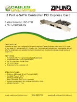
2.1.1. HDMI
®
Port
The integrated 19-pin HDMI
®
port uses an HDMI
®
Type A receptacle connector. The pinout of the HDMI
®
port is as
shown below.
Figure 6: HDMI
®
port pinout diagram
Pin
Signal Pin
Signal
1 TMDS Data2+ 2 TMDS Data2 Shield
3 TMDS Data2– 4 TMDS Data1+
5 TMDS Data1 Shield 6 TMDS Data1–
7 TMDS Data0+ 8 TMDS Data0 Shield
9 TMDS Data0– 10
TMDS Clock+
11
TMDS Clock Shield 12
TMDS Clock–
13
CEC 14
Reserved / HEC Data-
1
15
SCL
2
16
SDA
3
17
DDC/CEC/HEC Ground
18
+5 V Power
4
19
Hot Plug Detect and
HEC Data+
5
Table 1: HDMI
®
port pinout
Note:
1. Pin 15: SCL is for I²C Serial Clock for DDC.
2. Pin 16: SDA is for I²C Serial Data Line for DDC.
3. Pin 18: max 50 mA
/