Page is loading ...

0099002284E-00
Jump Starter
and DC Power Source
Arrancador
y Fuente de Poder de CC
Bloc d’alimentation
et aide démarrage
OWNERS MANUAL / MANUAL DEL USUARIO /
MANUEL D’UTILISATION
PLEASE SAVE THIS OWNERS MANUAL AND READ BEFORE EACH USE. This
manual will explain how to use the portable power safely and effectively. Please read and
follow these instructions and precautions carefully.
POR FAVOR CONSERVE ESTE MANUAL DEL USUARIO Y LEALO ANTES DE
CADA USO. En este manual le explica cómo utilizar la fuente de poder de manera
segura y conable. Por favor, lea y siga las siguientes instrucciones y precauciones.
ESSAYER DE GARDER LE MANUEL D’INSTRUCTIONS ET LE LIRE AVANT CHAQUE
UTILISATION. Ce manuel explique comment utiliser l’unité d’une façon sûre et efcace.
S’il vous plaît lisez et suivez ces instructions et précautions.
FOR MODELS / PARA MODELOS / POUR LES MODÈLES
DSR157
DSR158
DSR159
DSR160

CONTENTS
IMPORTANT SAFETY INSTRUCTIONS – SAVE THESE INSTRUCTIONS ..............................................5
PERSONAL PRECAUTIONS ......................................................................................................................6
CONNECTING THE JUMP STARTER ........................................................................................................6
FEATURES .................................................................................................................................................7
CHARGING THE INTERNAL BATTERY OF THE JUMP STARTER...........................................................8
OPERATING INSTRUCTIONS ...................................................................................................................9
MAINTENANCE INSTRUCTIONS ............................................................................................................10
MOVING AND STORAGE INSTRUCTIONS .............................................................................................10
TROUBLESHOOTING ..............................................................................................................................11
REPLACEMENT PARTS ...........................................................................................................................12
BEFORE RETURNING FOR REPAIRS ....................................................................................................13
LIMITED WARRANTY ...............................................................................................................................13

CONTENIDOS
INSTRUCCIONES IMPORTANTES DE SEGURIDAD – GUARDE ESTAS INSTRUCCIONES ............... 14
PRECAUCIONES PERSONALES ............................................................................................................15
CONECTAR EL ARRANCADOR ...............................................................................................................15
CARACTERÍSTICAS ................................................................................................................................16
PARA CARGAR LA BATERIA INTERNA DEL ARRANCADOR.................................................................17
INSTRUCCIONES DE OPERACIÓN ........................................................................................................18
INSTRUCCIONES DE MANTENIMIENTO ...............................................................................................19
INSTRUCCIONES PARA EL MANEJO Y ALMACENAMIENTO ...............................................................19
LOCALIZACIÓN Y SOLUCIÓN DE PROBLEMAS ...................................................................................20
REPUESTOS ............................................................................................................................................22
ANTES DE DEVOLVER A REPARACIONES ............................................................................................22
GARANTÍA LIMITADA ...............................................................................................................................23

TABLE DES MATIÈRES
CONSIGNES DE SÉCURITÉ IMPORTANTES – CONSERVER CES INSTRUCTIONS ..........................24
PRÉCAUTIONS PERSONNELLES ..........................................................................................................25
CONNECTE LE AIDE AU DÉMARRAGE .................................................................................................25
CARACTÉRISTIQUES ..............................................................................................................................26
CHARGEMENT DE LA BATTERIE INTERNE DE L’AIDE AU DÉMARRAGE ..........................................27
CONSIGNES D’UTILISATION ..................................................................................................................28
INSTRUCTIONS D’ENTRETIEN ..............................................................................................................29
INSTRUCTIONS DE STOCKAGE ET EMPLACEMENT ..........................................................................29
DÉPANNAGE ............................................................................................................................................30
PIÈCES DE RECHANGE ..........................................................................................................................32
AVANT DE RETOURNER POUR LES RÉPARATIONS ............................................................................ 32
GARANTIE LIMITÉE .................................................................................................................................33

• 5 •
CONTAINS SEALED, NON-SPILLABLE LEAD-ACID BATTERY. MUST BE DISPOSED OF PROPERLY.
WARNING: Possible explosion hazard. Contact with battery acid may cause severe burns and
blindness. Keep out of reach of children.
1. IMPORTANT SAFETY INSTRUCTIONS – SAVE THESE INSTRUCTIONS
WARNING: RISK OF EXPLOSIVE GASES.
WORKING IN THE VICINITY OF A LEAD-ACID BATTERY IS DANGEROUS. BATTERIES GENERATE
EXPLOSIVE GASES DURING NORMAL OPERATION. IT IS IMPORTANT THAT YOU FOLLOW
THESE INSTRUCTIONS EACH TIME YOU USE THE UNIT.
To reduce the risk of battery explosion, follow these instructions and those published by the battery
manufacturer and the manufacturer of any equipment you intend to use in the vicinity of a battery.
Review cautionary markings on these products and on the engine.
WARNING! RISK OF ELECTRIC SHOCK OR FIRE.
1.1 Read the entire manual before using this product. Failure to do so could result in serious injury or death.
1.2 Keep out of reach of children.
1.3 Do not put ngers or hands into any of the jump starter’s outlets.
1.4 Do not expose the jump starter to rain or snow.
1.5 Use only recommended attachments. Use of an attachment not recommended or sold by the jump
starter manufacturer may result in a risk of re, electric shock or injury to persons or damage to property.
1.6 To reduce the risk of damage to the electric plug or cord, pull by the plug rather than the cord when
disconnecting the jump starter.
1.7 To reduce the risk of electric shock, unplug the jump starter charger from the outlet before attempting
any maintenance or cleaning. Simply turning off the controls will not reduce this risk.
1.8 Do not operate the jump starter with damaged cables or clips; replace the damaged cable or clip
immediately.
1.9 Do not operate the jump starter if it has received a sharp blow, been dropped or otherwise damaged in
any way; take it to a qualied service person.
1.10 Do not disassemble the jump starter; take it to a qualied service person when service or repair is
required. Incorrect reassembly may result in a risk of re or electric shock.
WARNING! RISK OF EXPLOSIVE GASES.
1.11 To reduce the risk of a battery explosion, follow these instructions and those published by the battery
manufacturer and the manufacturer of any equipment you intend to use in the vicinity of the battery.
Review the cautionary markings on these products and on the engine.
1.12 This jump starter employs parts, such as switches and circuit breakers, that tend to produce arcs and
sparks. If used in a garage, locate this jump starter 18 inches (46 cm) or more above oor level.
Jump Starter and DC Power Source
OWNERS MANUAL
PLEASE SAVE THIS OWNERS MANUAL AND READ BEFORE EACH USE.
This manual will explain how to use the jump starter safely and effectively. Please
read and follow these instructions and precautions carefully.
FOR MODELS
DSR157
DSR158
DSR159
DSR160

• 6 •
2. PERSONAL PRECAUTIONS
WARNING! RISK OF EXPLOSIVE GASES. A SPARK NEAR THE BATTERY MAY CAUSE A BATTERY
EXPLOSION. TO REDUCE THE RISK OF A SPARK NEAR THE BATTERY:
2.1 NEVER smoke or allow a spark or ame in the vicinity of a battery or engine.
2.2 Do not permit the internal battery of the jump starter to freeze. Never charge a frozen battery.
2.3 To prevent sparking, NEVER allow clips to touch together or contact the same piece of metal.
2.4 When charging the internal battery, work in a well ventilated area and do not restrict the ventilation in any way.
2.5 Be sure the area around the battery is well ventilated while the jump starter is being used.
2.6 Remove personal metal items such as rings, bracelets, necklaces and watches when working with a
lead-acid battery. A lead-acid battery can produce a short-circuit current high enough to weld a ring or
the like to metal, causing a severe burn.
2.7 Be extra cautious, to reduce the risk of dropping a metal tool onto the battery. It might spark or short-
circuit the battery or other electrical part that may cause an explosion.
2.8 Consider having someone nearby to come to your aid when you work near a
lead-acid battery.
2.9 Have plenty of fresh water and soap nearby in case battery acid contacts your skin, clothing or eyes.
2.10 Wear complete eye and body protection, including safety goggles, face shield and protective clothing.
Avoid touching your eyes while working near the battery.
2.11 If battery acid contacts your skin or clothing, immediately wash the area with soap and water. If acid
enters your eye, immediately ood the eye with cold running water for at least 10 minutes and get
medical attention right away.
2.12 If battery acid is accidentally swallowed, drink milk, the whites of eggs or water.
DO NOT induce vomiting. Seek medical attention immediately.
WARNING! RISK OF CONTACT WITH BATTERY ACID. BATTERY ACID IS A HIGHLY CORROSIVE
SULFURIC ACID.
2.13 Clean the battery terminals before using the jump starter. During cleaning, keep airborne corrosion
from coming into contact with your eyes, nose and mouth. Use baking soda and water to neutralize the
battery acid and help eliminate airborne corrosion. Do not touch your eyes, nose or mouth.
2.14 Add distilled water to each cell until the battery acid reaches the level specied by the battery
manufacturer. Do not overll. For a battery without removable cell caps, such as valve regulated lead
acid batteries (VRLA), carefully follow the manufacturer’s instructions.
2.15 Read, understand and follow all instructions for the jump starter, battery, vehicle and any equipment
used near the battery and jump starter.
2.16 Determine the voltage of the battery by referring to the vehicle owner’s manual and make sure that the
output voltage of the jump starter is correct.
2.17 Make sure that the jump starter cable clips make tight connections.
3. CONNECTING THE JUMP STARTER
WARNING! A SPARK NEAR THE BATTERY MAY CAUSE A BATTERY EXPLOSION. TO REDUCE
THE RISK OF A SPARK NEAR THE BATTERY:
3.1 Attach the output cables to the battery and chassis as indicated below. Never allow the output clips to
touch each other.
3.2 Position the DC cables to reduce the risk of damage by the hood, door and moving or hot engine parts.
NOTE: If it is necessary to close the hood during the jump starting process, ensure that the hood does
not touch the metal part of the battery clips or cut the insulation of the cables.
3.3 Stay clear of fan blades, belts, pulleys and other parts that can cause injury.
3.4 Check the polarity of the battery posts. The POSITIVE (POS, P, +) battery post usually has a larger
diameter than the NEGATIVE (NEG, N, -) post.
3.5 Determine which post of the battery is grounded (connected) to the chassis. If the negative post is
grounded to the chassis (as in most vehicles), see step 3.6. If the positive post is grounded to the
chassis, see step 3.7.

• 7 •
3.6 For a negative-grounded vehicle, connect the POSITIVE (RED) clip from the jump starter to the
POSITIVE (POS, P, +) ungrounded post of the battery. Connect the NEGATIVE (BLACK) clip to the
vehicle chassis or engine block away from the battery. Do not connect the clip to the carburetor, fuel
lines or sheet-metal body parts. Connect to a heavy gauge metal part of the frame or engine block.
3.7 For a positive-grounded vehicle, connect the NEGATIVE (BLACK) clip from the jump starter to the
NEGATIVE (NEG, N, -) ungrounded post of the battery. Connect the POSITIVE (RED) clip to the vehicle
chassis or engine block away from the battery. Do not connect the clip to the carburetor, fuel lines or
sheet-metal body parts. Connect to a heavy gauge metal part of the frame or engine block.
3.8 When disconnecting the jump starter, turn all switches to off (if applicable), remove the clip from the
vehicle chassis, then remove the clip from the battery terminal.
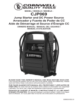
4. FEATURES
1
4 5
3
2
6
7
8
9
10
11
12
1. Heavy-duty battery clips
2. Display button
3. Digital display
4. USB button
5. USB Port
6. Jump starter ON/OFF switch
7. 12V DC socket
8. 12V DC charge port
9. Charger
10. Charging status LED
11. Bad Battery LED
12. Power LED
4.13 DIGITAL DISPLAY
When connected to a battery, the digital display can be used to indicate the battery’s voltage. When not
connected to a battery, the digital display can be used to indicate the percent of charge or the voltage of
the jump starter’s internal battery.
To check the internal battery’s charge status, make sure the rotary switch is in the OFF position, then
press the display button on the front of the jump starter. The digital display will show the battery’s percent
of charge. A fully charged battery will read 100%. Charge the internal battery if the display shows it is
under 100%.
NOTE: The internal battery’s percent of charge is most accurate when the jump starter has been
disconnected from all devices and charging sources for a few hours.
To check the voltage level of the jump starter’s internal battery, make sure the clips are attached to their
plastic storage holders and not touching each other, and then turn the rotary switch to the 12V position
(12V or 24V position on DSR160). The display will indicate the battery’s voltage.
To check the voltage level of the vehicle’s battery, make sure the switch in the OFF position, then
connect the clips to the vehicle’s battery. The display will indicate the battery’s voltage.

• 8 •
4.14 CLAMP LEDs (Models DSR158, DSR159 and DSR160)
Use the Display button to activate the clamp LEDs:
• Press the Display button once to show percent of charge.
• Press the button a second time, to turn on the clamp LEDs.
• Press the button a third time, to turn off the clamp LEDs.
4.15 CHARGER LED INDICATORS
POWER (green) LED lit: The charger is connected to AC power.
CHARGING STATUS INDICATOR (yellow/orange) LED ashing: The charger is in abort mode.
BAD BATTERY (red) LED lit: The charger has detected a problem with the battery.
See Troubleshooting for more information.
5. CHARGING THE INTERNAL BATTERY OF THE JUMP STARTER
IMPORTANT!
CHARGE IMMEDIATELY AFTER PURCHASE, AFTER EACH USE AND EVERY 30 DAYS, TO KEEP
THE UNIT’S INTERNAL BATTERY FULLY CHARGED AND PROLONG BATTERY LIFE.
To check the internal battery’s charge status, make sure the rotary switch is in the OFF position, then
press the display button on the front of the jump starter. The digital display will show the battery’s percent
of charge. A fully charged battery will read 100%. Charge the internal battery if the display shows it is
under 100%. Complete charging may take up to 48 hours.
5.1 GROUNDING AND AC POWER CORD CONNECTIONS
IMPORTANT: Only use the charger that was included with the jump starter to charge the internal battery
of the jump starter. Using a different charger could result in personal injury or property damage.
WARNING!
RISK OF ELECTRIC SHOCK OR FIRE.
This battery charger is for use on a nominal 120V circuit. The plug must be plugged into an outlet
that is properly installed in accordance with all local codes and ordinances. The plug pins must t the
receptacle (outlet). Do not use with an ungrounded system.
DANGER. Never alter the AC cord or plug provided – if it does not t the outlet, have a proper outlet
installed by a qualied electrician. An improper connection can result in a risk of an electric shock or
electrocution.
An extension cord should not be used unless absolutely necessary. Use of an improper extension cord
could result in a risk of re and electric shock. If an extension cord must be used, make sure:
• That the pins on the plug of the extension cord are the same number, size and shape as those of the plug
on the charger.
• That the extension cord is properly wired and in good electrical condition.
• That the wire size is large enough for the AC ampere rating of the charger,
as specied:
Length of cord (feet) 25 50 100 150
AWG* size of cord 18 18 18 16
*AWG-American Wire Gauge
5.2 CHARGING THE JUMP STARTER
1. Insert the charger output cord into the charge port on the front of the jump starter.
2. Plug the charger’s power cord into a grounded 120V AC electrical wall outlet.
3. The charger’s green
Power LED will light.
4. While the jump starter is charging, the marching dashes
will show on the digital display. When the
internal battery is fully charged, the display will show ioo. Complete charging may take up to 72 hours.
5. When the internal battery is fully charged, the charger will automatically go into maintain mode and
maintain the battery at full charge without damaging it.
6. When charging is complete, disconnect the charger from the AC power. Then remove the charger
output cord from the jump starter.

• 9 •
5.3 CHARGER MODES
Automatic charging mode
When an automatic charge is performed, the charger switches to maintain mode automatically after the
battery is charged.
Aborted Charge
If charging cannot be completed normally, charging will abort. When charging aborts, the charger’s
output is shut off. The Bad Battery
(red) LED will light and the yellow/orange
Charging Status
LED will ash. Do not continue attempting to charge the battery. Check the battery and replace, if
necessary.
Desulfation Mode
Desulfation could take 8 to 10 hours. If desulfation fails, charging will abort. The Bad Battery
(red)
LED will light and the yellow/orange
Charging Status LED will ash.
Completion of Charge
When the internal battery is fully charged, the display on the jump starter will showioo.
Maintain Mode (Float-Mode Monitoring)
When the internal battery is fully charged and the jump starter display showsioo, the charger has started
maintain mode. In this mode, the charger keeps the battery fully charged by delivering a small current when
necessary. If the charger has to provide its maximum maintain current for a continuous 12 hour period, it
will go into abort mode (see Aborted Charge). This is usually an indication of a bad battery; have the jump
starter checked.
6. OPERATING INSTRUCTIONS
6.1 JUMP STARTING A VEHICLE ENGINE
IMPORTANT: Using the jump starter without a battery installed in the vehicle will damage the vehicle’s
electrical system.
IMPORTANT: Do not use the jump starter while charging its internal battery.
1. Turn the vehicle’s ignition OFF before making cable connections.
2. Make sure the rotary switch on the front of the jump starter is in the OFF position. Connect the jump
starter to the battery following the precautions listed in section 3.
WARNING! RISK OF EXPLOSION.
If you have connected the clips backward, an audio alarm will sound. DO NOT turn the rotary switch to
the 12V (12V or 24V for model DSR160) position. This could cause serious damage to the jump starter
or the vehicle. Reverse the connections and the audio alarm will stop.
3. If no audio alarm sounds, turn the rotary switch to the 12V position (12V or 24V position for model
DSR160). The clips are now powered.
4. Crank the engine. If the engine does not start within 5-8 seconds, stop cranking and wait at least 1
minute before attempting to start the vehicle again. (This permits the jump starter to cool down.)
5. After the engine starts, disconnect the black clip (-), then the red clip (+) in that order, and clip them
back onto the jump starter storage holders.
6. Recharge the jump starter as soon as possible after use.
NOTE: If the cables are connected to a 24 volt system when the switch is in the
12 volt position, the audio alarm will sound continuously. TURN OFF the jump starter immediately or
internal battery damage could occur.
NOTE: If the switch is in the 12V or 24V position or the jump starter is connected to a battery for more than
ve minutes, four beeps will sound. This is a reminder to turn the jump starter off and/or disconnect it from
the vehicle’s battery when not in use.
WARNING! RISK OF EXPLOSION.
To prevent sparking, NEVER allow the clips to touch together or to contact the same piece of metal.
Never attempt to jump start a frozen battery.

• 10 •
6.2 POWERING A 12V DC DEVICE:
The jump starter is a power source for all 12V DC accessories that are equipped with a 12V accessory plug.
Use it for power outages and shing or camping trips. Estimated usage time is listed in the following chart.
1. Make sure the device to be powered is OFF before inserting a 12V DC accessory plug into the 12V
DC socket.
2. Ensure the battery clips are securely clipped on the storage holders.
3. Open the protective cover of the 12V DC power outlet on the front of the jump starter.
4. Plug the 12V DC device into the 12V DC power outlet, and turn the 12V DC device on (if required).
5. If the 12V DC device draws more than 15A or has a short circuit, the internal circuit breaker of the jump
starter will trip and disconnect the power to the device. Disconnect the 12V DC device. The breaker will
automatically reset a short time after an overload is disconnected.
6. Recharge immediately after unplugging the 12V DC device.
NOTE: The DC power outlet is wired directly to the internal battery. Extended operation of a 12V DC
device may result in excessive battery drain.
6.3 USING THE USB PORT
The USB port provides up to 2.1A at 5V DC.
1. Ensure the battery clips are securely clipped on the storage holders.
2. Press the USB button on the front of the unit.
3. Plug the device into the USB port on the front of the unit.
4. Turn the USB device on.
5. Reverse these steps when nished using the USB port.
6. Charge the jump starter as soon as possible after using the USB port.
7. MAINTENANCE INSTRUCTIONS
7.1 After use and before performing maintenance, unplug and disconnect the jump starter.
7.2 Use a dry cloth to wipe all battery corrosion and other dirt or oil from the battery clips, cords and the
jump starter case.
7.3 Ensure that all of the jump starter components are in place and in good working condition.
7.4 All servicing should be performed by qualied service personnel.
8. MOVING AND STORAGE INSTRUCTIONS
8.1 Store inside, in a cool, dry place.
8.2 Do not store the clips on the handle, clipped together, on or around metal, or clipped to cables. The clips
on the jump starter are live when the switch is in the ON position and will produce arcing or sparking if
they come in contact with each other. To prevent accidental arcing, always place the switch in the OFF
position and keep the clips on the storage holders when not using it to jump start a vehicle.
8.3 If the jump starter is moved around the shop or transported to another location, take care to avoid/prevent
damage to the cords, clips and jump starter. Failure to do so could result in personal injury or property damage.
IMPORTANT: Do not use and/or store the jump starter in or on any area or surface where damage
could occur if the internal battery should unexpectedly leak acid.
8.4 IMPORTANT:
• CHARGE IMMEDIATELY AFTER PURCHASE
• KEEP FULLY CHARGED
Charge the jump starter’s internal battery immediately after purchase, after every use and every 30 days.
All batteries are affected by temperature. The ideal storage temperature is at 70°F. The internal battery will
gradually self-discharge (lose power) over time, especially in warm environments. Leaving the battery in a
discharged state may result in permanent battery damage. To ensure satisfactory performance and avoid
permanent damage, charge the internal battery every month.

• 11 •
9. TROUBLESHOOTING
Jump Starter
PROBLEM POSSIBLE CAUSE SOLUTION
The jump starter won’t jump
start my car.
Clips are not making a good
connection to the battery.
The jump starter battery is not
charged.
Larger engines require more
current to turn engine over, and
may require a larger jump starter.
The vehicle’s battery is defective.
Check for poor connection to battery
and frame. Make sure connection
points are clean. Rock clips back and
forth for a better connection.
Check the battery charge status by
pressing the button on the front of the
jump starter. See the Digital Display
section of this manual.
Use larger jump starter.
Have the battery checked.
The jump starter won’t
power my 12V device.
The 12V device is not turned on.
The jump starter’s battery is not
charged.
The 12V device draws more than
15A or has a short circuit.
Turn on the 12V device.
Check the battery charge status by
pressing the button on the front of the
jump starter. See the Digital Display
section of this manual.
Disconnect the 12V device. The internal
breaker will automatically reset after
a minute or two. Try the 12V device
again. If it happens again, replace the
12V device.
The battery in the jump
starter won’t hold a charge.
The battery is bad (will not accept
a charge).
Have the battery checked.
The jump starter alarm is
on.
The connections to the battery are
reversed.
(Models DSR157, DSR158,
DSR159) The electrical system is
24 volts.
The internal battery voltage of the
jump starter is getting low.
Disconnect the jump starter from the
battery and reverse the clips.
Disconnect the jump starter
immediately.
Recharge the jump starter as soon as
possible.
The display shows “F11”. Charger is not plugged in correctly.
The charger plug is not making a
good connection.
Damaged charger plug or cable.
Make sure charger plug is inserted
completely into jump starter charging
port.
Make sure plug is clean and free of any
obstructions.
Contact customer service.

• 12 •
Charger
PROBLEM REASON SOLUTION
All three LEDs come on for 2
seconds, then turn off.
The charger is plugged into an AC
outlet.
No problem; this is normal.
The green
Power LED
does not light when charger
is properly connected.
AC outlet is dead.
Poor electrical connection.
Check for open fuse or circuit breaker
supplying AC outlet.
Check power cord and extension cord
for a loose tting plug.
The red
Bad Battery
LED is lit and yellow/orange
LED is ashing.
The battery voltage is still below
10V after 2 hours of charging.
(or)
In maintain mode, the output current
is more than 1.5A for 12 hours.
Desulfation was unsuccessful.
The battery may be defective. Make
sure there are no loads on the battery.
If there are, remove them. If there are
none, have the battery checked or
replaced.
The battery may be defective. Have
battery checked or replaced.
The red
Bad Battery
LED is lit.
The battery is sulfated.
Lack of progress is detected and
battery voltage is below 14.2V.
The battery’s initial voltage is below
12.2V and the total input is less
than 1.5 Ah.
The battery voltage drops below
12.2V during Maintain Mode.
The charger is in desulfation mode.
Continue charging for several hours.
If not successful, have the battery
checked.
The battery may be overheated. If
so, allow the battery to cool. The
battery may be too large or have a
short circuit. Have battery checked or
replaced.
The battery capacity is too low, or the
battery is too old. Have it checked or
replaced.
The battery won’t hold a charge. May
be caused by a drain on the battery or
the battery could be bad. Make sure
there are no loads on the battery. If
there are remove them. If there are
none, have the battery checked or
replaced.
10. REPLACEMENT PARTS
DSR2 charger .................................................................................................................... 2299003063Z
Replacement battery for DSR157 ...................................................................................... 5799000014Z
Replacement battery for DSR158 ...................................................................................... 5799000010Z
Replacement battery for DSR159 ...................................................................................... 5799000038Z
Replacement battery for DSR160 (uses 2) ........................................................................ 5799000051Z

• 13 •
11. BEFORE RETURNING FOR REPAIRS
For REPAIRS OR RETURNS, visit 365rma.com
Visit batterychargers.com for Replacement Parts.
12. LIMITED WARRANTY
Go to batterychargers.com to register your product online.
SCHUMACHER ELECTRIC CORPORATION, 801 BUSINESS CENTER DRIVE, MOUNT PROSPECT,
IL 60056-2179, MAKES THIS LIMITED WARRANTY TO THE ORIGINAL RETAIL PURCHASER OF
THIS PRODUCT. THIS LIMITED WARRANTY IS NOT TRANSFERABLE OR ASSIGNABLE.
Schumacher Electric Corporation (the “Manufacturer”) warrants this jump starter for one (1) year and
the internal battery for ninety (90) days from the date of purchase at retail against defective material
or workmanship that may occur under normal use and care. If your unit is not free from defective
material or workmanship, Manufacturer’s obligation under this warranty is solely to repair or replace
your product with a new or reconditioned unit at the option of the Manufacturer. It is the obligation of
the purchaser to forward the unit, along with proof of purchase and mailing charges prepaid to the
Manufacturer or its authorized representatives in order for repair or replacement to occur.
Manufacturer does not provide any warranty for any accessories used with this product that are
not manufactured by Schumacher Electric Corporation and approved for use with this product.
This Limited Warranty is void if the product is misused, subjected to careless handling, repaired, or
modied by anyone other than Manufacturer or if this unit is resold through an unauthorized retailer.
Manufacturer makes no other warranties, including, but not limited to, express, implied or statutory
warranties, including without limitation, any implied warranty of merchantability or implied warranty of
tness for a particular purpose. Further, Manufacturer shall not be liable for any incidental, special or
consequential damage claims incurred by purchasers, users or others associated with this product,
including, but not limited to, lost prots, revenues, anticipated sales, business opportunities, goodwill,
business interruption and any other injury or damage. Any and all such warranties, other than the
limited warranty included herein, are hereby expressly disclaimed and excluded. Some states do not
allow the exclusion or limitation of incidental or consequential damages or length of implied warranty,
so the above limitations or exclusions may not apply to you. This warranty gives you specic legal
rights and it is possible you may have other rights which vary from this warranty.
THIS LIMITED WARRANTY IS THE ONLY EXPRESS LIMITED WARRANTY AND THE
MANUFACTURER NEITHER ASSUMES OR AUTHORIZES ANYONE TO ASSUME OR MAKE
ANY OTHER OBLIGATION TOWARDS THE PRODUCT OTHER THAN THIS WARRANTY.
Schumacher
®
is a registered trademark of Schumacher Electric Corporation.

• 14 •
Arrancador y Fuente de Poder de CC
MANUAL DEL USUARIO
POR FAVOR CONSERVE ESTE MANUAL DEL USUARIO Y LEALO ANTES DE
CADA USO. En este manual le explica cómo utilizar la fuente de poder de manera
segura y conable. Por favor, lea y siga las siguientes instrucciones y precauciones.
PARA MODELOS
DSR157
DSR158
DSR159
DSR160
CONTIENE UNA BATERÍA SELLADA DE ÁCIDO-PLOMO NO DERRAMABLE QUE DEBE
DESECHARSE APROPIADAMENTE.
ADVERTENCIA: Posible riesgo de una explosión. El contacto con una batería de ácido puede causar
quemaduras y ceguera. Manténgase alejado de los niños.
1. INSTRUCCIONES IMPORTANTES DE SEGURIDAD – GUARDE ESTAS INSTRUCCIONES
ADVERTENCIA: RIESGO DE GASES EXPLOSIVOS.
TRABAJAR CERCA DE UNA BATERÍA DE PLOMO-ÁCIDO ES PELIGROSO. LAS BATERÍAS GENERAN
GASES EXPLOSIVOS DURANTE SU FUNCIONAMIENTO NORMAL. ES IMPORTANTE QUE SIGA LAS
INSTRUCCIONES CADA VEZ QUE UTILICE LA UNIDAD.
Para disminuir el riesgo de explosión de la batería, siga estas instrucciones, al igual que las
recomendaciones publicadas por el fabricante de la batería y de cualquier equipo que se utilizará cerca
de la batería. Verique las señales de advertencia que se hayan colocado en estos productos y en el motor.
ADVERTENCIA: EL RIESGO DE DESCARGA ELÉCTRICA O INCENDIO.
1.1 Lea el manual completo antes de utilizar este producto. Cualquier falla podría resultar en serias lesiones
o podría ser mortal.
1.2 Manténgase alejado de los niños.
1.3 No coloque los dedos o las manos en cualquiera de los enchufes de la unidad.
1.4 No exponga la unidad a la lluvia o la nieve.
1.5 Utilice solamente accesorios recomendados. El uso de un accesorio no recomendado o suministrado
por el fabricante de la unidad puede provocar riesgo de incendio, descarga eléctrica o lesiones a
personas o daño a la propiedad.
1.6 Para reducir el riesgo de daños al enchufe o cable eléctrico, jale del enchufe en lugar de jalar del cable
al desconectar la unidad.
1.7 Para reducir el riesgo de descarga eléctrica, desenchufe el cargador de la unidad del tomacorriente
antes de intentar llevar a cabo cualquier actividad de mantenimiento o limpieza. El simple apagado de
los controles no reducirá este riesgo.
1.8 No opere la unidad si los cables o las pinzas están dañados; reemplace los cables y las pinzas
inmediatamente.
1.9 No utilice la unidad si el mismo recibió un golpe fuerte, si se cayó o si sufrió daños de cualquier otra
forma; hágalo revisar por una persona capacitada que efectúe reparaciones.
1.10 No desarme la unidad; hágalo revisar por una persona capacitada que efectúe reparaciones cuando
necesite servicio de mantenimiento o una reparación. Volver a ensamblar la fuente de poder en forma
incorrecta puede provocar riesgo de incendio o descarga eléctrica.
ADVERTENCIA: RIESGO DE GASES EXPLOSIVOS.
1.11 Para reducir el riesgo de explosión de una batería, siga estas instrucciones y aquellas publicadas por el
fabricante de la batería y por el fabricante de cualquier equipo que intente utilizar en la proximidad de la
batería. Revise las pautas de precaución en estos productos y en el motor.
1.12 Este unidad está equipado con partes, tales como, interruptores y cortacircuitos, que tienden a originar
chispas y cortos. Si se utiliza en la cochera, utilice la unidad 18 pulgadas (46 cm) o más del nivel del suelo.

• 15 •
2. PRECAUCIONES PERSONALES
ADVERTENCIA: RIESGO DE GASES EXPLOSIVOS. UNA CHISPA CERCA DE LA BATERÍA HACER
QUE LA BATERÍA EXPLOTE. PARA REDUCIR EL RIESGO DE CHISPAS CERCA DE LA BATERÍA:
2.1 NUNCA fume o permita la presencia de chispas o llamas en la proximidad de una batería o motor.
2.2 No deje que la batería interna se congele. Nunca cargue una batería congelada.
2.3 Para prevenir cortos, NUNCA permita que las pinzas se junten o hagan contacto por medio de un mismo metal.
2.4 La carga de la batería interna, debe realizarse en áreas bien ventiladas, sin restricción alguna.
2.5 Asegúrese que el área alrededor de la batería esté bien ventilado, mientras que el motor de arranque
salto se está utilizando.
2.6 No utilice elementos personales de metal tales como anillos, pulseras, collares y relojes al trabajar con
una batería de plomo-ácido. Una batería de plomo-ácido puede producir una corriente de cortocircuito
lo sucientemente elevada como para soldar un anillo o provocar efectos similares sobre el metal,
causando una quemadura de gravedad.
2.7 Tenga especial cuidado para reducir el riesgo de dejar caer una herramienta de metal sobre la batería.
Esto podría provocar chispas o un cortocircuito en la batería o en cualquier otra pieza eléctrica que
podría provocar una explosión.
2.8 Considere la idea de que alguna persona se encuentre cerca suyo para poder ayudarlo cuando trabaje
en forma cercana a una batería de plomo-ácido.
2.9 Cuente con una gran cantidad de agua potable y jabón a mano en caso de que el ácido de la batería
tenga contacto con su piel, ropa u ojos.
2.10 Use adecuada protección visual y de vestir, esto incluye gafas de seguridad, mascarilla y ropa
adecuada. Evite tocarse los ojos mientras labora cerca de la batería.
2.11 Si el ácido de la batería tiene contacto con su piel o su ropa, lave de inmediato el área afectada con
agua y jabón. En caso de que ingrese ácido en un ojo, sumerja el mismo de inmediato bajo agua
potable corriente por al menos 10 minutos y obtenga atención médica en forma inmediata.
2.12 Si el ácido de la batería es accidentalmente ingerido, se recomienda beber leche, clara de huevo o
agua. NO provoque vómito. Busque ayuda médica de inmediato.
ADVERTENCIA: RIESGO DE CONTACTO CON EL ÁCIDO DE LA BATERÍA. EL ÁCIDO DE LA
BATERÍA ES UN ÁCIDO SULFÚRICO ALTAMENTE CORROSIVO.
2.13 Limpie los terminales de la batería antes de usar la unidad. Durante la limpieza, evite que la corrosión producida
por aire tenga contacto con sus ojos, nariz y boca. Utilice bicarbonato de sodio y agua para neutralizar el ácido
de la batería y ayudar a eliminar la corrosión producida por aire. No toque ojos, nariz o boca.
2.14 Agregue agua destilada a cada pila hasta que el ácido de la batería alcance el nivel especicado por
el fabricante de la batería. No provoque derrames. En lo que concierne a baterías que no cuentan con
tapas extraíbles para pilas, tales como baterías de plomo-ácido reguladas por válvulas (VRLA, por sus
siglas en inglés), siga cuidadosamente las instrucciones del fabricante.
2.15 Lea, comprenda y siga todas las instrucciones para la fuente de poder, la batería, el vehículo y cualquier
equipo que se utilice cerca de la batería y la unidad.
2.16 Determine el voltaje de la batería consultando el manual del usuario del vehículo y asegúrese de que la
tensión de salida del voltaje el aparato sea la correcta.
2.17 Asegúrese de que las pinzas de la unidad se encuentren rmemente conectadas.
3. CONECTAR EL ARRANCADOR
ADVERTENCIA: UNA CHISPA PROVOCADA CERCA DE LA BATERÍA PUEDE CAUSAR LA EXPLOSIÓN
DE LA BATERÍA. PARA REDUCIR EL RIESGO DE PROVOCAR CHISPAS CERCA DE LA BATERÍA:
3.1 Conecte los cables de salida a la batería y al chasis según lo indicado abajo. Nunca permita que las
pinzas hagan contacto una con el otra.
3.2 Ubique los cables de C.C. para reducir el riesgo de daños a la cubierta, a la puerta y a las piezas
móviles o calientes del motor. NOTA: Si es necesario cerrar el cofre durante el proceso de arranca,
asegúrese que el cofre no toque parte metálica de la batería o pele los cables.
3.3 Manténgase alejado de las paletas del ventilador, correas, poleas y otras piezas que podrían provocar
lesiones.
3.4 Verique la polaridad de los bornes de la batería. El borne POSITIVO (POS, P, +) de la batería
generalmente posee un diámetro mayor al borne NEGATIVO (NEG, N, -).

• 16 •
3.5 Determine qué borne de la batería hace descarga a tierra (se encuentra conectado) con el chasis. Si el
borne negativo hace descarga a tierra con el chasis (como en la mayor parte de los vehículos), ver el
paso 3.6. Si el borne positivo hace descarga a tierra con el chasis, ver el paso 3.7.
3.6 En un vehículo con descarga a tierra por borne negativo, conecte el gancho POSITIVO (ROJO) de la
fuente de poder de batería al borne POSITIVO (POS, P, +) sin descarga a tierra de la batería. Conecte
el gancho NEGATIVO (NEGRO) al chasis del vehículo o al bloque motor alejado de la batería. No
conecte el gancho al carburador, líneas de combustible o cuerpos metálicos. Conecte a una pieza
metálica de calibre grueso del marco o del bloque motor.
3.7 En un vehículo con descarga a tierra por borne positivo, conecte el gancho NEGATIVO (NEGRO) de la
fuente de poder de batería al borne NEGATIVO (NEG, N, -) sin descarga a tierra de la batería. Conecte
el gancho POSITIVO (ROJO) al chasis del vehículo o al bloque motor alejado de la batería. No conecte
al carburador, líneas de combustible o cuerpos metálicos. Conecte a una pieza metálica de calibre
grueso del marco o del bloque motor.
3.8 Al desconectar la unidad apague todos los interruptores (si es aplicable), retire el gancho del chasis del
vehículo y luego retire el gancho del terminal perteneciente a la batería.
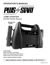
4. CARACTERÍSTICAS
1. Abrazaderas de durabilidad
2. Botón de pantalla
3. Pantalla digital
4. Botón de USB
5. Puerto USB
6. Interruptor de arrancador ON / OFF
7. Toma de corriente de 12 V de CD
8. Puerto de carga de 12V de CD
9. Cargador
10. Indicador LED de estado de carga
11. Indicador LED de batería defectuosa
12. LED de alimentación
1
4 5
3
2
6
7
8
9
10
11
12
4.13 PANTALLA DIGITAL
Cuando se conecta a una batería, la pantalla digital puede usarse para indicar el voltaje de la batería.
Cuando no se conecta la pantalla digital a una batería, puede usarse para indicar el porcentaje de carga
de la batería interna del arrancador auxiliar.
Para vericar el estado de carga de la batería interna, asegúrese de que el selector rotatorio se
encuntre en la posición OFF después oprima el botó de tablero localizado en el frente de la unidad. El
indicador digital demostrará el porcentaje de carga. Una batería totalmente cargada leerá 100%. Cargue
la batería interna si la carátula muestra carga por debajo del 100%.
NOTA: El porcentaje de carga de la batería interna es más connable si la fuente de poder ha sido
desconectada de todos los accesorios y conexiones por unas horas.
Para comprobar el nivel de voltaje de la batería interna del arrancador de la batería, asegúrese de que
las pinzas estén acopladas a sus sujetadores de almacenamiento de plástico y no se toquen entre sí, y
luego gire el selector giratorio a la posición 12 V (posición 12 V o 24 V en el modelo DSR160). La pantalla
indicará el voltaje de la batería.
Para vericar el nivel de voltaje de la batería
del vehículo, asegúrese de que el interruptor
se encuentre en la posición OFF (Apagado),
después conecte las pinzas a la batería
del vehículo. La carátula indicará el voltaje
de la batería.

• 17 •
4.14 LED DE ABRAZADERAS (Modelos DSR158, DSR159 y DSR160)
Use el botón Pantalla para activar los LEDs de las abrazaderas:
• Presione el botón Pantalla una vez para mostrar el porcentaje de carga.
• Presione el botón por segunda vez para encender los LEDs de las abrazaderas.
• Presione el botón por tercera vez para apagar los LEDs de las abrazaderas.
4.15 INDICADORES LED DE CARGADOR
LED ALIMENTACIÓN (verde) encendido: El cargador está conectado a la red eléctrica.
INDICADOR DE ESTADO DE CARGA: LED amarillo / naranja parpadea:
El cargador está en modo anulada.
LED BATERÍA DEFECTUOSA (rojo) encendido: El cargador ha detectado un problema
con la batería. Consulte Localización y Solución de Problemas para obtener más información.
5. PARA CARGAR LA BATERIA INTERNA DEL ARRANCADOR
IMPORTANTE: CARGUE LA BATERIA INTERNA INMEDIATAMENTE DESPUES DE COMPRARLA,
DESPUES DE CADA USO Y CADA 30 DIAS PARA ASI MANTENER LAUNIDAD CARGADA
COMPLETAMENTE.
Para comprobar el estado de carga de la batería interna, asegúrese de que el interruptor giratorio esté en
la posición APAGADO y luego presione el botón Pantalla en la parte delantera del arrancador de la batería.
La pantalla digital mostrará el porcentaje de la carga de la batería. Una batería completamente cargada
mostrará 100 %. Cargue la batería interna si la pantalla muestra una cifra inferior a 100 %. La carga
completa puede tardar hasta 48 horas.
5.1 CONEXIONES A TIERRA Y ENERGÍA DE CA
IMPORTANTE: Utilice únicamente el cargador que se incluye con el arrancador de la batería para cargar su
batería interna. El uso de un cargador diferente podría tener como consecuencia lesiones personales o daños
a la propiedad.
ADVERTENCIA: RIESGO DE DESCARGA ELÉCTRICA O INCENDIO.
Este cargador de batería está destinado a un uso en un circuito con tensión nominal de 120 V. El
enchufe se debe conectar a un tomacorriente adecuadamente instalado y que cuente con descarga a
tierra de acuerdo con todas las ordenanzas y códigos. Los pasadores del enchufe deben adaptarse al
receptáculo (tomacorriente). No utilizar con un sistema que no posea descarga a tierra.
PELIGRO: Nunca altere el cable o enchufe de C.A. suministrado, si no se ajusta al tomacorriente, haga
instalar un tomacorriente adecuado con descarga a tierra por medio de un electricista capacitado. Una
conexión inadecuada puede provocar un riesgo de descarga eléctrica o electrocución.
No debe utilizarse un cable de extensión a menos que sea absolutamente necesario. El uso de un cable de
extensión incorrecto podría tener como consecuencia un riesgo de incendio y descargas eléctricas. Si es
necesario utilizar un cable de extensión, asegúrese de lo siguiente:
• Las clavijas del enchufe del cable de extensión debe ser el mismo número, tamaño y forma que las del
enchufe del cargador.
• Asegúrese de que el cable de extensión esté conectado correctamente y en buenas condiciones
eléctricas.
• El tamaño del cable debe ser lo sucientemente extenso para el calibre de amperios del cargador de
CA, como se especica a continuación:
Longitud del cable (pies) 25 50 100 150
Calibre del cable AWG* 18 18 18 16
*AWG-American Wire Gauge

• 18 •
5.2 CARGAR EL ARRANCADOR DE LA BATERÍA
1. Inserte el cable de salida del cargador al puerto de carga en la parte delantera del arrancador
de la batería.
2. Enchufe el cable de alimentación del cargador en un tomacorriente eléctrico de pared de 120 V
de CA con conexión a tierra.
3. El LED de Encendido verde
del cargador se encenderá.
4. Mientras el arrancador de la batería esté cargando, las líneas en movimiento
aparecerán en la
pantalla digital. Cuando la batería interna esté completamente cargada, la pantalla mostrará ioo.
La carga puede tardar hasta 72 horas en completarse.
5. Cuando la batería interna esté completamente cargada, el cargador pasará automáticamente al
modo de mantenimiento y mantendrá la batería a plena carga sin dañarla.
6. Después de cargar, desconecte el cargador del suministro principal. Luego, retire todas las
conexiones del arrancador.
5.3 MODOS DEL CARGADOR
Modo de Carga Automática
Cuando se realiza una carga automática, el cargador cambia del maintain mode automáticamente
después que la batería se cargue.
Carga Anulada
Si no se puede completar la carga normalmente, la carga se anulará. Cuando la carga se interrumpe, la
salida del cargador se apaga. El LED Batería Defectuosa
(rojo) se iluminará y el amarillo / naranja
Estado de Carga LED parpadeará. No continúe tratando de cargar esta batería. Compruebe la batería y
reemplazar si es necesario.
Modo de Desulfatación
La desulfatación puede durar 8 a 10 horas. Si la desulfatación falla, la carga se abortará. El LED Batería
Defectuosa
(rojo) se iluminará y el amarillo / naranja
Estado de Carga LED parpadeará.
Finalización de la Carga
Cuando la batería interna esté completamente cargada, la pantalla en el arrancador de la batería mostrará ioo.
Modo de Mantenimiento (Monitoreo a Modo de Flote)
Cuando la batería interna esté completamente cargada y la pantalla del arrancador de la batería
muestreioo, el cargador habrá iniciado el modo de mantenimiento. En este modo el cargador mantiene
la batería totalmente cargada mediante una pequeña corriente cuando corresponda. Si el cargador
tiene que funcionar al máximo en corriente continua de mantenimiento a un periodo de 12 horas, se
transladará al modo de anulada (véase la sección Carga Anulada). Esto es ocacionalmente causado
por una pérdida de energía en la batería o la batería está dañada. Esto suele ser una indicación de una
batería mala; revise el arrancador de la batería.
6. INSTRUCCIONES DE OPERACIÓN
6.1 PARA ARRANCAR EL MOTOR DEL VEHÍCULO
IMPORTANTE: El uso del arrancador de la batería sin una batería instalada en el vehículo puede dañar el
sistema eléctrico del vehículo.
IMPORTANTE: No utilice la unidad mientras carga la batería interna.
1. Apague el vehículo antes de hacer conexiones de cables.
2. Asegúrese que el interruptor giratorio en el frente del arrancador auxiliar está en la posición OFF.
Conectar la unidad a la batería teniendo en cuenta las precauciones que guran en las seccion 3.
ADVERTENCIA: RIESGO DE EXPLOSIÓN.
Si ha conectado las pinzas al revés, escuchará un sonido de alarma. NO gire el botón-interruptor a la
posición de 12V (12V o 24V para el modelo DSR160). Esto podría causar serios daños a la fuente de
poder o al vehículo. Conecte los cables a la inversa y el zumbido dejará de sonar.
3. Si no suena una alarma auditiva gire el interruptor giratorio a la posición de 12V (12V o 24V para modelo
DSR160). Las abrazaderas tienen potencia ahora.
4. Arranque el motor. Si el motor no da marcha de entre los 5 y 8 segundos, detenga el arranque y espere
1 minuto antes de intentar arrancarlo de nuevo. (Esto permitirá a la fuente de poder que se recupere.)

• 19 •
5. Una vez que el motor haya arrancado, desconecte la pinza negra (-) y después la roja (+) en ese orden
y sujete las pinzas en los soportes de los lados.
6. Cargue la fuente de poder tan pronto sea posible, después de usarse.
NOTA: Si los cables están conectados a un sistema de 24 voltios cuando el interruptor está en la
posición de 12 voltios, la alarma auditiva sonará continuamente. APAGUE el arrancador auxiliar
inmediatamente o puede ocurrir daño en la batería interna.
NOTA: Si el interruptor está en la posición de 12V o 24V, o el arrancador auxiliar está conectado a
una batería por más de 5 minutos, se emitirán cuatro pitidos. Este es un recordatorio para apagar el
arrancador auxiliar y/o desconectarlo de la batería del vehículo cuando no está en uso.
ADVERTENCIA: RIESGO DE EXPLOSIÓN.
Para prevenir chispas, NUNCA, permita que las pinzas hagan contacto entre sí mismas o por medio de un
metal. Nunca intente arrancar un a batería congelada.
6.2 PARA HACER FUNCIONAR UN APARATO DE 12V DE CD
La unidad es una fuente de poder para cualquier accesorio de 12V de corriente directa que estén
equipados con enchufe de 12V. Utilícelo durante apagones, pesca o días de campo. El tiempo
aproximado de uso se describe en la siguiente gráca.
1. Asegúrese de que el dispositivo a alimentar esté APAGADO antes de insertar un enchufe accesorio
de CC de 12 V en la toma de CC de 12 V.
2. También asegúrese de que las pinzas queden sujetas en su lugar.
3. Abra la tapa protectora de entrada del aparato de CD en el frente de la unidad.
4. Conecte el aparato de 12V de CD en la salida de corriente de la unidad y enciéndalo (si requiere).
5. Si el aparato de 12V de CD absorbe más de 15A o tiene un corto circuito, el interruptor de circuitos
interno de la funidad se reactivará e interrumpirá el paso de corriente al aparato. Desconecte el
aparato de 12V de CD. El interruptor se restablecerá automáticamente un corto tiempo después de
desconectarse una sobrecarga.
6. Recargue inmediatamente después de desenchufar en aparato de 12V de CD.
El enchufe está conectado directamente a la batería interna. Una operación en exceso del aparato de
12V de CD podría descargar la batería excesivamente.
6.3 EL USO DE PUERTO USB
El puerto USB provee poco más de 2,1A a 5V de CD.
1. Asegúrese que las pinzas estén jas en el compartimiento.
2. Pulse el botón USB en la parte frontal de la unidad.
3. Enchufe el aparato en el puerto USB de la parte trasera de la consola.
4. Encienda el aparato USB.
5. Una vez terminado el uso del USB, desconecte en forma reversible.
6. Cargue la unidad tan pronto deje de usar el puerto USB.
7. INSTRUCCIONES DE MANTENIMIENTO
7.1 Después de usar y antes de realizar mantenimiento, desenchufe y desconecte la unidad (ver secciones 3 y 4).
7.2 Utilice un paño seco para limpiar la corrosión de toda la batería y otra suciedad o aceite de los
terminales, cables y carcasa de la unidad.
7.3 Asegúrese de que todas las piezas de la unidad estén bien instaladas y en buenas condiciones para su función.
7.4 Cualquier servicio debe realizarse por personal calicado en el ramo.
8. INSTRUCCIONES PARA EL MANEJO Y ALMACENAMIENTO
8.1 Almacene en el interior, en un lugar fresco y seco.
8.2 No guarde las pinzas en asas, enganchados entre sí, en o cerca de metales o enganchados en cables.
Las pinzas en la unidad están energizadas. Cuando el interruptor se encuentra en la posición ON y
producen arco o chispas si hacen contacto entre sí. Para evitar arco accidental, siempre mantenga las
pinzas en los soportes de almacenaje y el interruptor en la posición OFF cuando el arrancador no se
está usando para arranque inmediato de un vehículo.

• 20 •
8.3 Si la unidad se mueve alrededor del taller o se transporta a otra localidad, trate de evitar/prevenir daño a los
cables, pinzas y al arrancador. El ignorar estas recomendaciones, podría llegar a causarle daños personales
o de inmueble.
IMPORTANTE: No use o almacene la unidad, bajo ninguna circustancia, en áreas donde puede causar
daño alguno en caso de que la batería derrame ácido.
8.4 IMPORTANTE:
• CARGUE INMEDIATAMENTE DESPUÉS DE CADA USO.
• MANTENGA LA UNIDAD COMPLETAMENTE CARGADA.
Cargue la fuente de poder inmediatamente después de comprarla, después de cada uso y cada 30 días.
La temperatura afecta a todas las baterías. La temperatura ideal de almacenaje es a los 70 grados
Fahrenheit. La batería interna se va descargando (pierde potencia) con el pasar del tiempo, especialmente
en los ambientes cálidos. Si se deja la batería en estado de descarga, puede sufrir daños permanentes.
Para asegurar el rendimiento satisfactorio y evitar daños permanentes, cargue la batería interna mensualmente.
9. LOCALIZACIÓN Y SOLUCIÓN DE PROBLEMAS
Arrancador
PROBLEMA CAUSA POSIBLE SOLUCIÓN
La unidad no arranca
mi auto.
Las pinzas no hacen buena
conexión a la batería.
La batería interna no está cargada.
Los motores más grandes
requieren más corriente para girar
el motor y pueden requerir un
arrancador de batería más grande.
La batería del vehículo esta
defectuosa.
Asegúrese de que existe buena
conexión a la batería y la carrocería.
También que los puntos de las
conexiones estén limpios. Gire las
pinzas para una conexión efectiva.
Verique la condición de carga de la
batería girando el interruptor situado
enfrente de la unidad. Consulte la sección
de Indicador Digital en este manual.
Use un arrancador de batería más
grande.
Haga un chequeo de la batería.
La unidad no pone a
funcionar mi aparato de
12V.
El aparato de 12V no enciende.
La batería interna no está cargada.
El aparato de 12V absorbe más de
15A, o tiene un corto circuito.
Allumez le 12V la machine.
Encienda el aparato de 12V.
Verique la condición de carga de la
batería girando el interruptor situado
enfrente de la unidad. Consulte la sección
de Indicador Digital en este manual.
Desconecte el aparato de 12V. El
interruptor interno se autoprogramará
después de uno o dos minutes. Si sucede
lo mismo, reemplace el aparato de 12V.
La batería de la unidad no
retiene la carga.
La batería está en malas
condiciones (No recibirá carga).
Haga un chequeo de la batería.
/