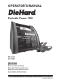
DieHard Portable Power 1150 28.71988 User manual
- Category
- Car battery chargers
- Type
- User manual
This manual is also suitable for
DieHard Portable Power 1150 28.71988 is a versatile and powerful jump starter that can provide a quick and easy solution to starting a dead battery. With its compact design and ability to charge various devices, it's a must-have for emergencies on the road or power outages at home. It features multiple safety precautions to prevent accidents and ensure safe operation, making it suitable for individuals with varying levels of technical expertise.
DieHard Portable Power 1150 28.71988 is a versatile and powerful jump starter that can provide a quick and easy solution to starting a dead battery. With its compact design and ability to charge various devices, it's a must-have for emergencies on the road or power outages at home. It features multiple safety precautions to prevent accidents and ensure safe operation, making it suitable for individuals with varying levels of technical expertise.


-
 1
1
-
 2
2
-
 3
3
-
 4
4
-
 5
5
-
 6
6
-
 7
7
-
 8
8
-
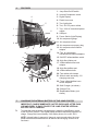 9
9
-
 10
10
-
 11
11
-
 12
12
-
 13
13
-
 14
14
-
 15
15
-
 16
16
-
 17
17


DieHard Portable Power 1150 28.71988 User manual
- Category
- Car battery chargers
- Type
- User manual
- This manual is also suitable for
DieHard Portable Power 1150 28.71988 is a versatile and powerful jump starter that can provide a quick and easy solution to starting a dead battery. With its compact design and ability to charge various devices, it's a must-have for emergencies on the road or power outages at home. It features multiple safety precautions to prevent accidents and ensure safe operation, making it suitable for individuals with varying levels of technical expertise.
Ask a question and I''ll find the answer in the document
Finding information in a document is now easier with AI
Related papers
-
Sears 28.71988 User manual
-
-
DieHard 28.71494 User manual
-
-
-
-
-
-
-
Other documents
-
Schumacher 71489 Jump Starter and DC Power Source Owner's manual
-
 Plus Start 71489 Owner's manual
-
AVAPOW A27 User manual
-
 Cornwell CJP069 Owner's manual
-
Stanley FatMax PPRH5KL Quick start guide
-
Schumacher Carlyle CJP400 Jump Starter and DC Power Source Carlyle CJP550 Jump Starter and DC Power Source Carlyle CJP700 Jump Starter and DC Power Source Carlyle CJP850 Jump Starter and DC Power Source Owner's manual
-
-
-
HQ W9-EPH-19-22BN Datasheet
-
Napa CJP400 Owner's manual

