Page is loading ...

Application Report
SNAA039A–July 2007–Revised May 2013
AN-1591 LM49370 PCM/I
2
S Bridge
.....................................................................................................................................................
ABSTRACT
This application report describes the LM49370 PCM/I
2
S Bridge.
Contents
1 PCM/I
2
S Bridge Overview .................................................................................................. 3
2 PCM/I
2
S Bridge Explained ................................................................................................. 3
3 PCM and I
2
S Running at the Same Sample Rate ...................................................................... 5
4 I
2
S and PCM Running at Different Sample Rates Within the Same Sample Rate Family ........................ 6
5 PCM and I
2
S Running at Sample Rates from Different Sample Rate Families ................................... 13
6 Setting the Correct Clocks ............................................................................................... 15
7 Two-Way Voice Communication or Music Playback via Bluetooth Headset Without Using the PCM/I
2
S
Bridge ....................................................................................................................... 17
8 Stereo Bluetooth Headsets ............................................................................................... 18
9 Revision History ........................................................................................................... 18
List of Figures
1 System Level Diagram ..................................................................................................... 3
2 System Level Diagram with LM49370 PCM-I
2
S Bridge................................................................ 3
3 Overall PCM/I
2
S Bridge Diagram ......................................................................................... 4
4 PCM and I
2
S Running at the Same Sample Rate (Voice Communication, Voice Record, or MP3/MP4
Playback)..................................................................................................................... 5
5 PCM and I
2
S Running at Different Sample Rates Within the Same Sample Rate Family (Voice Record) ..... 6
6 PCM and I
2
S Running at Different Sample Rates Within the Same Sample Rate Family (MP3/MP4
Playback)..................................................................................................................... 7
7 PCM and I
2
S Running at Different Sample Rates from Different Sample Rate Families (Voice Record) ..... 14
8 PCM and I
2
S Running at Different Sample Rates from Different Sample Rate Families (MP3/MP4
Playback) ................................................................................................................... 14
9 LM49370 Clock Network ................................................................................................. 15
10 Audio Port CLOCK/SYNC Options...................................................................................... 16
11 PCM Audio Port CLOCK/SYNC Options............................................................................... 16
12 Using the LM49370 with a Dedicated RF Module for Two-way Voice Communication via Bluetooth
Headset .................................................................................................................... 17
13 Alternative Method for Two-way Voice Communication via Bluetooth ............................................ 17
14 Using the LM49370 to Route FM Radio or TV Audio to a Bluetooth Headset ................................... 18
15 FM Radio or TV Tuner Playback via Bluetooth Headset............................................................. 18
List of Tables
1 PCM/I
2
S Bridge Settings (I
2
S and PCM Operating at the Same Sample Rate) .................................... 5
2 Converting 8kHz to Other Sample Rates Within the Same Family (OSR = 128) .................................. 8
3 Converting 16kHz to Other Sample Rates Within the Same Family (OSR = 128)................................. 9
4 Converting 24kHz to Other Sample Rates Within the Same Family (OSR = 128) ............................... 10
5 Converting 32kHz to Other Sample Rates Within the Same Family (OSR = 128) ............................... 11
All trademarks are the property of their respective owners.
1
SNAA039A–July 2007–Revised May 2013
AN-1591 LM49370 PCM/I
2
S Bridge
Submit Documentation Feedback
Copyright © 2007–2013, Texas Instruments Incorporated

www.ti.com
6 Converting 48kHz to Other Sample Rates Within the Same Family (OSR = 128) ............................... 12
7 Converting any 48kHz Related Sample Rate to Other Sample Rates Within the Same Family (OSR =
125).......................................................................................................................... 12
8 Converting a Sample Rate to Another Sample Rate from a Different Sample Rate Family .................... 13
2
SNAA039A–July 2007–Revised May 2013
AN-1591 LM49370 PCM/I
2
S Bridge
Submit Documentation Feedback
Copyright © 2007–2013, Texas Instruments Incorporated

Bluetooth Headset
Bluetooth
Transceiver
Baseband Processor
Audio Port 1
PCM
(mono)
I
2
S
(Stereo)
PCM-I
2
S
Bridge
LM49370
802.15.1
Bluetooth Headset
Bluetooth
Transceiver
Stereo DAC with
Loudspeaker and
Headphone
Amplifiers
Baseband Processor
Audio Port 1 Audio Port 2
PCM
(mono)
I
2
S
(Stereo)
802.15.1
www.ti.com
PCM/I
2
S Bridge Overview
1 PCM/I
2
S Bridge Overview
With an ever increasing feature set found in today’s mobile phones, reducing software overhead and
baseband processor loading is high priority for any mobile phone design. The most straightforward way to
accomplish this without sacrificing any features is to delegate some of the baseband processor’s duties
over to an external IC.
One such duty is the management of multiple digital audio formats such as mono PCM (for voice) and
stereo I
2
S (for music). Bluetooth headset support and MP3/MP4 playback capability are standard features
that facilitate the need to manage different digital audio interfaces within the same system. As shown in
Figure 1, a Bluetooth transceiver typically uses a mono PCM audio format during a voice communication
whereas an external audio DAC uses a stereo I
2
S audio format for MP3/MP4 playback.
Figure 1. System Level Diagram
The onboard PCM/I
2
S bridge of the LM49370 allows the baseband processor to manage just a single
digital audio interface thereby reducing processor load and associating software overhead. The LM49370
links directly to the Bluetooth transceiver, freeing up a valuable audio port on the baseband
microprocessor. The PCM/I
2
S bridge can convert a mono PCM interface into a stereo I
2
S interface or
conversely.
Figure 2. System Level Diagram with LM49370 PCM-I
2
S Bridge
2 PCM/I
2
S Bridge Explained
The PCM/I
2
S bridge is specifically targeted for mobile phone applications that require the use of a mono
Bluetooth headset. A mono Bluetooth headset is used for voice record, music playback, and two-way
voice communication.
In the voice record scenario, the PCM/I
2
S bridge accepts voice data in mono PCM format at a particular
sample rate from a Bluetooth transceiver. The incoming PCM audio data is then converted to a stereo I
2
S
format at a programmable sample rate that is sent out through the LM49370’s I
2
S output port over to the
baseband processor for recording.
In the music playback scenario, the PCM/I
2
S bridge accepts music data in stereo I
2
S format at a particular
sample rate from the baseband processor. The left and right I
2
S data can then be summed together and
converted to a mono PCM format. The converted mono PCM music data is then routed to the Bluetooth
transceiver at a programmable sample rate via the LM49370’s PCM output port.
3
SNAA039A–July 2007–Revised May 2013
AN-1591 LM49370 PCM/I
2
S Bridge
Submit Documentation Feedback
Copyright © 2007–2013, Texas Instruments Incorporated

I
2
S
I
2
S_TX_SEL
I
2
S_SDO
I
2
S_SDI
Automatic Handshaking
Sample & Hold
PCM
PCM_TX_SEL
PCM_SDO
PCM_SDI
STEREO/
MONO
MONO_SUM_MODE
MONO_SUM_SEL
DAC_INPUT_SEL
at f
S(IN)
FIR
Interp
DSDM
DAC_SRC_MODE
Stereo DAC
IIR
Dec
Mono ADC
CIC
ADC_SRC_MODE
PCM/I
2
S Bridge Explained
www.ti.com
For two-way voice communication, it is assumed that the I
2
S port on the baseband processor handles the
voice receive and transmit for this particular example. Also, the I
2
S and PCM interfaces must run at the
same sample rate. The PCM/I
2
S bridge accepts voice data in mono PCM format at a particular sample
rate from a Bluetooth transceiver. The incoming PCM audio data is then converted to a stereo I
2
S format
and is sent out through the LM49370’s I
2
S output port over to the baseband processor for transmit. The
PCM/I
2
S bridge accepts voice data in stereo I
2
S format from the baseband processor. The left and right
I
2
S data can then be summed together and converted to a mono PCM format. The converted mono PCM
music data is then routed to the Bluetooth transceiver via the LM49370’s PCM output port for voice
receive. For systems that use a dedicated RF IC for voice receive and transmit, the LM49370 features a
differential analog input (CP_IN) and output (CP_OUT) pair that directly connect to the analog interface of
the RF IC while the LM49370’s PCM port still directly interfaces with the Bluetooth transceiver. This an
alternative to using the PCM/I
2
S bridge for two way voice communication via a Bluetooth headset (see
Figure 12).
One limitation of the PCM/I
2
S Bridge is that both the PCM and I
2
S interfaces of the LM49370 should not
simultaneously operate as slaves. Both the PCM and I
2
S interfaces can run as masters, or one master
and the other slave. However, it is not recommended to run both interfaces as slaves if the PCM and I
2
S
clock sources cannot be synchronized exactly. When using the PCM/I
2
S Bridge, set the FORCERQ bit to
‘1’ to activate the LM49370’s R and Q dividers (see Figure 9) which allow PCM or I
2
S clock generation in
master mode.
The compression format of the PCM interface is transparent to the PCM/I
2
S bridge. The PCM interface
can operate in linear mode, A-law compressed, or μ-law compressed without any impact on PCM/I
2
S
bridge operation. The I
2
S bus format (standard or left justified) is also transparent to the PCM/I
2
S bridge.
The PCM/I
2
S bridge operates with minimal power consumption and also supports sample rate conversion
(SRC). However, there are three primary modes of PCM/I
2
S Bridge operation which are dependent on the
sample rates of the PCM and I
2
S buses. To better understand the different models of operation, two
sample rate “families” have been identified, 48kHz and 44.1kHz. The 48kHz sample rate family consists of
8kHz, 16kHz, 24kHz, 32kHz, and 48kHz. The 44.1kHz sample rate family consists of 11.025kHz,
22.05kHz, and 44.1kHz.
The three modes of operation of the PCM/I
2
S Bridge are:
1. The PCM and I
2
S interfaces run at the same sample rate without sample rate conversion.
2. The PCM and I
2
S interfaces run at different sample rates that are within the same sample rate family.
3. The PCM and I
2
S interfaces run at different sample rates that are not of the same family.
Figure 3. Overall PCM/I
2
S Bridge Diagram
4
SNAA039A–July 2007–Revised May 2013
AN-1591 LM49370 PCM/I
2
S Bridge
Submit Documentation Feedback
Copyright © 2007–2013, Texas Instruments Incorporated

I
2
S
I
2
S_TX_SEL
I
2
S_SDO
I
2
S_SDI
Automatic Handshaking
PCM
PCM_TX_SEL
PCM_SDO
PCM_SDI
STEREO/
MONO
MONO_SUM_MODE
MONO_SUM_SEL
www.ti.com
PCM and I
2
S Running at the Same Sample Rate
3 PCM and I
2
S Running at the Same Sample Rate
The recommended PCM/I
2
S Bridge mode of operation is to have both the PCM and I
2
S interfaces run at
the same sample rate. This mode of operation consumes the least amount of power because there is no
sample rate conversion. The LM49370’s stereo DAC and mono ADC can both be completely powered off
in this mode of operation. For voice recording through the Bluetooth headset, set I2S_TX_SELECT to ‘01’
(PCM Receiver) as this will route the mono PCM data received from PCM_SDI to I2S_SDO.
The mono signal is automatically copied onto both the left and right channels of the I
2
S bus. For MP3/MP4
playback (or voice receive via the baseband processor) through the Bluetooth headset, set
PCM_TX_SELECT to ‘1’ (Mono Sum Circuit) as this will route the stereo I
2
S data received from I2S_SDI
to PCM_SDO via the mono sum circuit. The mono sum circuit acts like a stereo to mono converter. It
takes the stereo I
2
S data and produces a mono output. The mono output can be either the I
2
S left channel,
the I
2
S right channel, or a mono signal created by adding the left and right I
2
S channels. This is controlled
by MONO_SUM_MODE.
This is also the only PCM/I
2
S Bridge mode of operation that allows two-way voice communication via
Bluetooth headset for systems that implement the baseband processor’s I
2
S port for voice receive and
transmit.
Table 1. PCM/I
2
S Bridge Settings (I
2
S and PCM Operating at the Same Sample Rate)
I
2
C Field
(1)
Setting Result
PCM_TX_SEL 1 Mono Sum Circuit
I2S_TX_SEL 01 PCM Receiver
DAC_INPUT_SEL 11 Disabled
MONO_SUM_SEL 1 I
2
S Receiver
MONO_SUM_MODE 00 Mono Out = (Left I
2
S + Right I
2
S) / 2
ADC_SRC_MODE 0 Disabled
DAC_SRC_MODE 0 Disabled
(1)
Refer to the LM49370 datasheet for detailed information regarding the I
2
C register settings.
Figure 4. PCM and I
2
S Running at the Same Sample Rate
(Voice Communication, Voice Record, or MP3/MP4 Playback)
5
SNAA039A–July 2007–Revised May 2013
AN-1591 LM49370 PCM/I
2
S Bridge
Submit Documentation Feedback
Copyright © 2007–2013, Texas Instruments Incorporated

I
2
S
I
2
S_TX_SEL
I
2
S_SDO
Automatic Handshaking
Sample & Hold
PCM
PCM_SDI
STEREO/
MONO
MONO_SUM_MODE
MONO_SUM_SEL
DAC_INPUT_SEL
at f
S(IN)
FIR
Interp
DAC_SRC_MODE
Stereo DAC
IIR
Dec
Mono ADC
ADC_SRC_MODE
I
2
S and PCM Running at Different Sample Rates Within the Same Sample Rate Family
www.ti.com
4 I
2
S and PCM Running at Different Sample Rates Within the Same Sample Rate
Family
In the case of system level restraints, the I
2
S and PCM interfaces may have to operate at different sample
rates while running simultaneously. The PCM/I
2
S Bridge can be used as a sample rate converter either to
upsample or downsample the incoming data stream. As long as the sample rates of the I
2
S and PCM
interfaces are within the same sample rate family, portions of the LM49370’s stereo DAC and mono ADC
can be powered down.
This mode of operation consumes more power due to the sample rate conversion process. Therefore, it is
recommended to avoid sample rate conversion if it is not required.
This mode requires access to the stereo DAC’s interpolated output. The interpolated DAC output can be
resampled directly through the I
2
S interface or it can be sent to the mono sum circuit and then fed to the
Sample and Hold block. The output of the Sample and Hold block is then decimated by the ADC’s IIR
filter. The resulting ADC output can then be routed to either the I
2
S or PCM interface.
Throughout this document, there will be many references to f
S(IN)
and f
S(OUT)
. The variable f
S(IN)
represents
the sample rate of the receiving interface (I
2
S or PCM) of the PCM/I
2
S Bridge, and f
S(OUT)
represents the
sample rate of the transmitting interface (I
2
S or PCM) of the PCM/I
2
S Bridge. For Bluetooth voice
recording, f
S(IN)
represents the PCM sample rate and f
S(OUT)
represents the I
2
S sample rate. For Bluetooth
MP3/MP4 playback, f
S(IN)
represents the I
2
S sample rate and f
S(OUT)
represents the PCM sample rate.
The I
2
S (or PCM) interface can directly resample the DAC’s interpolated output only if the following
conditions are met:
Condition 1: f
S(IN)
< f
S(OUT)
, which is equivalent to upsampling
Condition 2: ((f
S(IN)
/ f
S(OUT)
) * (OSR)) = an integer number, where OSR is the oversampling ratio of
the DAC and ADC.
If these conditions are not met, then the interpolated DAC output has to be resampled using the Sample
and Hold block. One such scenario that requires the use of the Sample and Hold block is converting an
f
S(IN)
of 8kHz to an f
S(OUT)
of 24kHz. Assuming an OSR of 128, Condition 2 is violated because ((8kHz) /
24kHz) × (128)) results in a non-integer value of 42.667. Another scenario that requires the use of the
Sample and Hold block is downsampling an f
S(IN)
of 48kHz to an f
S(OUT)
of 8kHz, which is violation of
Condition 1. It is important to note that the DAC and ADC can operate with an OSR of 125 or 128.
Figure 5. PCM and I
2
S Running at Different Sample Rates Within the Same Sample Rate Family
(Voice Record)
6
SNAA039A–July 2007–Revised May 2013
AN-1591 LM49370 PCM/I
2
S Bridge
Submit Documentation Feedback
Copyright © 2007–2013, Texas Instruments Incorporated

I
2
S
I
2
S_SDI
Automatic Handshaking
Sample & Hold
PCM
PCM_TX_SEL
PCM_SDO
STEREO/
MONO
MONO_SUM_MODE
MONO_SUM_SEL
DAC_INPUT_SEL
at f
S(IN)
FIR
Interp
DAC_SRC_MODE
Stereo DAC
IIR
Dec
Mono ADC
ADC_SRC_MODE
www.ti.com
I
2
S and PCM Running at Different Sample Rates Within the Same Sample Rate Family
Figure 6. PCM and I
2
S Running at Different Sample Rates Within the Same Sample Rate Family
(MP3/MP4 Playback)
The following tables can be used as a guide to correctly set the PCM/I
2
S Bridge where f
S(IN)
and f
S(OUT)
are
from the same sample rate family:
Although the tables only cover the 48kHz sample rate family, the same principles can be applied to
sample rate conversion within the 44.1kHz sample rate family.
7
SNAA039A–July 2007–Revised May 2013
AN-1591 LM49370 PCM/I
2
S Bridge
Submit Documentation Feedback
Copyright © 2007–2013, Texas Instruments Incorporated

I
2
S and PCM Running at Different Sample Rates Within the Same Sample Rate Family
www.ti.com
Table 2. Converting 8kHz to Other Sample Rates Within the Same Family (OSR = 128)
f
S(IN)
f
S(OUT)
Voice Record Settings MP3 Playback Settings
8kHz 8kHz Refer to Table 1 Refer to Table 1
16kHz PCM_TX_SELECT = X PCM_TX_SELECT = 1
I2S_TX_SELECT = 10 I2S_TX_SELECT = XX
DAC_INPUT_SEL = 01 DAC_INPUT_SEL = 00
MONO_SUM_SEL = 0 MONO_SUM_SEL = 0
MONO_SUM_MODE = 00 MONO_SUM_MODE = 00
ADC_SRC_MODE = 0 ADC_SRC_MODE = 0
DAC_SRC_MODE = 1 DAC_SRC_MODE = 1
24kHz PCM_TX_SELECT = X PCM_TX_SELECT = 0
I2S_TX_SELECT = 00 I2S_TX_SELECT = XX
DAC_INPUT_SEL = 01 DAC_INPUT_SEL = 00
MONO_SUM_SEL = 0 MONO_SUM_SEL = 0
MONO_SUM_MODE = 00 MONO_SUM_MODE = 00
ADC_SRC_MODE = 1 ADC_SRC_MODE = 1
DAC_SRC_MODE = 1 DAC_SRC_MODE = 1
32kHz PCM_TX_SELECT = X PCM_TX_SELECT = 1
I2S_TX_SELECT = 10 I2S_TX_SELECT = XX
DAC_INPUT_SEL = 01 DAC_INPUT_SEL = 00
MONO_SUM_SEL = 0 MONO_SUM_SEL = 0
MONO_SUM_MODE = 00 MONO_SUM_MODE = 00
ADC_SRC_MODE = 0 ADC_SRC_MODE = 0
DAC_SRC_MODE = 1 DAC_SRC_MODE = 1
48kHz PCM_TX_SELECT = X PCM_TX_SELECT = 0
I2S_TX_SELECT = 00 I2S_TX_SELECT = XX
DAC_INPUT_SEL = 01 DAC_INPUT_SEL = 00
MONO_SUM_SEL = 0 MONO_SUM_SEL = 0
MONO_SUM_MODE = 00 MONO_SUM_MODE = 00
ADC_SRC_MODE = 1 ADC_SRC_MODE = 1
DAC_SRC_MODE = 1 DAC_SRC_MODE = 1
8
SNAA039A–July 2007–Revised May 2013
AN-1591 LM49370 PCM/I
2
S Bridge
Submit Documentation Feedback
Copyright © 2007–2013, Texas Instruments Incorporated

www.ti.com
I
2
S and PCM Running at Different Sample Rates Within the Same Sample Rate Family
Table 3. Converting 16kHz to Other Sample Rates Within the Same Family (OSR = 128)
f
S(IN)
f
S(OUT)
Voice Record Settings MP3 Playback Settings
16kHz 8kHz PCM_TX_SELECT = X PCM_TX_SELECT = 0
I2S_TX_SELECT = 00 I2S_TX_SELECT = XX
DAC_INPUT_SEL = 01 DAC_INPUT_SEL = 00
MONO_SUM_SEL = 0 MONO_SUM_SEL = 0
MONO_SUM_MODE = 00 MONO_SUM_MODE = 00
ADC_SRC_MODE = 1 ADC_SRC_MODE = 1
DAC_SRC_MODE = 1 DAC_SRC_MODE = 1
16kHz Refer to Table 1 Refer to Table 1
24kHz PCM_TX_SELECT = X PCM_TX_SELECT = 0
I2S_TX_SELECT = 00 I2S_TX_SELECT = XX
DAC_INPUT_SEL = 01 DAC_INPUT_SEL = 00
MONO_SUM_SEL = 0 MONO_SUM_SEL = 0
MONO_SUM_MODE = 00 MONO_SUM_MODE = 00
ADC_SRC_MODE = 1 ADC_SRC_MODE = 1
DAC_SRC_MODE = 1 DAC_SRC_MODE = 1
32kHz PCM_TX_SELECT = X PCM_TX_SELECT = 1
I2S_TX_SELECT = 10 I2S_TX_SELECT = XX
DAC_INPUT_SEL = 01 DAC_INPUT_SEL = 00
MONO_SUM_SEL = 0 MONO_SUM_SEL = 0
MONO_SUM_MODE = 00 MONO_SUM_MODE = 00
ADC_SRC_MODE = 0 ADC_SRC_MODE = 0
DAC_SRC_MODE = 1 DAC_SRC_MODE = 1
48kHz PCM_TX_SELECT = X PCM_TX_SELECT = 0
I2S_TX_SELECT = 00 I2S_TX_SELECT = XX
DAC_INPUT_SEL = 01 DAC_INPUT_SEL = 00
MONO_SUM_SEL = 0 MONO_SUM_SEL = 0
MONO_SUM_MODE = 00 MONO_SUM_MODE = 00
ADC_SRC_MODE = 1 ADC_SRC_MODE = 1
DAC_SRC_MODE = 1 DAC_SRC_MODE = 1
9
SNAA039A–July 2007–Revised May 2013
AN-1591 LM49370 PCM/I
2
S Bridge
Submit Documentation Feedback
Copyright © 2007–2013, Texas Instruments Incorporated

I
2
S and PCM Running at Different Sample Rates Within the Same Sample Rate Family
www.ti.com
Table 4. Converting 24kHz to Other Sample Rates Within the Same Family (OSR = 128)
f
S(IN)
f
S(OUT)
Voice Record Settings MP3 Playback Settings
24kHz 8kHz PCM_TX_SELECT = X PCM_TX_SELECT = 0
I2S_TX_SELECT = 00 I2S_TX_SELECT = XX
DAC_INPUT_SEL = 01 DAC_INPUT_SEL = 00
MONO_SUM_SEL = 0 MONO_SUM_SEL = 0
MONO_SUM_MODE = 00 MONO_SUM_MODE = 00
ADC_SRC_MODE = 1 ADC_SRC_MODE = 1
DAC_SRC_MODE = 1 DAC_SRC_MODE = 1
16kHz PCM_TX_SELECT = X PCM_TX_SELECT = 0
I2S_TX_SELECT = 00 I2S_TX_SELECT = XX
DAC_INPUT_SEL = 01 DAC_INPUT_SEL = 00
MONO_SUM_SEL = 0 MONO_SUM_SEL = 0
MONO_SUM_MODE = 00 MONO_SUM_MODE = 00
ADC_SRC_MODE = 1 ADC_SRC_MODE = 1
DAC_SRC_MODE = 1 DAC_SRC_MODE = 1
24kHz Refer to Table 1 Refer to Table 1
32kHz PCM_TX_SELECT = X PCM_TX_SELECT = 1
I2S_TX_SELECT = 10 I2S_TX_SELECT = XX
DAC_INPUT_SEL = 01 DAC_INPUT_SEL = 00
MONO_SUM_SEL = 0 MONO_SUM_SEL = 0
MONO_SUM_MODE = 00 MONO_SUM_MODE = 00
ADC_SRC_MODE = 0 ADC_SRC_MODE = 0
DAC_SRC_MODE = 1 DAC_SRC_MODE = 1
48kHz PCM_TX_SELECT = X PCM_TX_SELECT = 1
I2S_TX_SELECT = 10 I2S_TX_SELECT = XX
DAC_INPUT_SEL = 01 DAC_INPUT_SEL = 00
MONO_SUM_SEL = 0 MONO_SUM_SEL = 0
MONO_SUM_MODE = 00 MONO_SUM_MODE = 00
ADC_SRC_MODE = 0 ADC_SRC_MODE = 0
DAC_SRC_MODE = 1 DAC_SRC_MODE = 1
10
SNAA039A–July 2007–Revised May 2013
AN-1591 LM49370 PCM/I
2
S Bridge
Submit Documentation Feedback
Copyright © 2007–2013, Texas Instruments Incorporated

www.ti.com
I
2
S and PCM Running at Different Sample Rates Within the Same Sample Rate Family
Table 5. Converting 32kHz to Other Sample Rates Within the Same Family (OSR = 128)
f
S(IN)
f
S(OUT)
Voice Record Settings MP3 Playback Settings
32kHz 8kHz PCM_TX_SELECT = X PCM_TX_SELECT = 0
I2S_TX_SELECT = 00 I2S_TX_SELECT = XX
DAC_INPUT_SEL = 01 DAC_INPUT_SEL = 00
MONO_SUM_SEL = 0 MONO_SUM_SEL = 0
MONO_SUM_MODE = 00 MONO_SUM_MODE = 00
ADC_SRC_MODE = 1 ADC_SRC_MODE = 1
DAC_SRC_MODE = 1 DAC_SRC_MODE = 1
16kHz PCM_TX_SELECT = X PCM_TX_SELECT = 0
I2S_TX_SELECT = 00 I2S_TX_SELECT = XX
DAC_INPUT_SEL = 01 DAC_INPUT_SEL = 00
MONO_SUM_SEL = 0 MONO_SUM_SEL = 0
MONO_SUM_MODE = 00 MONO_SUM_MODE = 00
ADC_SRC_MODE = 1 ADC_SRC_MODE = 1
DAC_SRC_MODE = 1 DAC_SRC_MODE = 1
24kHz PCM_TX_SELECT = X PCM_TX_SELECT = 0
I2S_TX_SELECT = 00 I2S_TX_SELECT = XX
DAC_INPUT_SEL = 01 DAC_INPUT_SEL = 00
MONO_SUM_SEL = 0 MONO_SUM_SEL = 0
MONO_SUM_MODE = 00 MONO_SUM_MODE = 00
ADC_SRC_MODE = 1 ADC_SRC_MODE = 1
DAC_SRC_MODE = 1 DAC_SRC_MODE = 1
32kHz Refer to Table 1 Refer to Table 1
48kHz PCM_TX_SELECT = X PCM_TX_SELECT = 0
I2S_TX_SELECT = 00 I2S_TX_SELECT = XX
DAC_INPUT_SEL = 01 DAC_INPUT_SEL = 00
MONO_SUM_SEL = 0 MONO_SUM_SEL = 0
MONO_SUM_MODE = 00 MONO_SUM_MODE = 00
ADC_SRC_MODE = 1 ADC_SRC_MODE = 1
DAC_SRC_MODE = 1 DAC_SRC_MODE = 1
11
SNAA039A–July 2007–Revised May 2013
AN-1591 LM49370 PCM/I
2
S Bridge
Submit Documentation Feedback
Copyright © 2007–2013, Texas Instruments Incorporated

I
2
S and PCM Running at Different Sample Rates Within the Same Sample Rate Family
www.ti.com
Table 6. Converting 48kHz to Other Sample Rates Within the Same Family (OSR = 128)
f
S(IN)
f
S(OUT)
Voice Record Settings MP3 Playback Settings
48kHz 8kHz PCM_TX_SELECT = X PCM_TX_SELECT = 0
I2S_TX_SELECT = 00 I2S_TX_SELECT = XX
DAC_INPUT_SEL = 01 DAC_INPUT_SEL = 00
MONO_SUM_SEL = 0 MONO_SUM_SEL = 0
MONO_SUM_MODE = 00 MONO_SUM_MODE = 00
ADC_SRC_MODE = 1 ADC_SRC_MODE = 1
DAC_SRC_MODE = 1 DAC_SRC_MODE = 1
16kHz PCM_TX_SELECT = X PCM_TX_SELECT = 0
I2S_TX_SELECT = 00 I2S_TX_SELECT = XX
DAC_INPUT_SEL = 01 DAC_INPUT_SEL = 00
MONO_SUM_SEL = 0 MONO_SUM_SEL = 0
MONO_SUM_MODE = 00 MONO_SUM_MODE = 00
ADC_SRC_MODE = 1 ADC_SRC_MODE = 1
DAC_SRC_MODE = 1 DAC_SRC_MODE = 1
24kHz PCM_TX_SELECT = X PCM_TX_SELECT = 0
I2S_TX_SELECT = 00 I2S_TX_SELECT = XX
DAC_INPUT_SEL = 01 DAC_INPUT_SEL = 00
MONO_SUM_SEL = 0 MONO_SUM_SEL = 0
MONO_SUM_MODE = 00 MONO_SUM_MODE = 00
ADC_SRC_MODE = 1 ADC_SRC_MODE = 1
DAC_SRC_MODE = 1 DAC_SRC_MODE = 1
32kHz PCM_TX_SELECT = X PCM_TX_SELECT = 0
I2S_TX_SELECT = 00 I2S_TX_SELECT = XX
DAC_INPUT_SEL = 01 DAC_INPUT_SEL = 00
MONO_SUM_SEL = 0 MONO_SUM_SEL = 0
MONO_SUM_MODE = 00 MONO_SUM_MODE = 00
ADC_SRC_MODE = 1 ADC_SRC_MODE = 1
DAC_SRC_MODE = 1 DAC_SRC_MODE = 1
48kHz Refer to Table 1 Refer to Table 1
Table 7. Converting any 48kHz Related Sample Rate to Other Sample Rates Within the Same
Family (OSR = 125)
f
S(IN)
f
S(OUT)
Voice Record Settings MP3 Playback Settings
PCM_TX_SELECT = X PCM_TX_SELECT = 0
I2S_TX_SELECT = 00 I2S_TX_SELECT = XX
Any 48kHz
DAC_INPUT_SEL = 01 DAC_INPUT_SEL = 00
Any 48kHz
Related
Related MONO_SUM_SEL = 0 MONO_SUM_SEL = 0
Sample Rate
Sample Rate
MONO_SUM_MODE = 00 MONO_SUM_MODE = 00
that is not f
S(IN)
ADC_SRC_MODE = 1 ADC_SRC_MODE = 1
DAC_SRC_MODE = 1 DAC_SRC_MODE = 1
12
SNAA039A–July 2007–Revised May 2013
AN-1591 LM49370 PCM/I
2
S Bridge
Submit Documentation Feedback
Copyright © 2007–2013, Texas Instruments Incorporated

www.ti.com
PCM and I
2
S Running at Sample Rates from Different Sample Rate Families
5 PCM and I
2
S Running at Sample Rates from Different Sample Rate Families
Whenever the sample rates of the I
2
S and PCM interfaces are running at sample rates from different
sample rate families (for example f
S(IN)
= 44.1kHz and f
S(OUT)
= 8kHz), the PCM/I
2
S bridge requires that the
stereo DAC and mono ADC be fully turned on. The incoming digital audio path (either I
2
S or PCM) has to
be routed to the stereo DAC in order to do the complete digital to analog conversion. The left and right
analog DAC outputs are then summed together and routed back through the ADC in order to perform the
analog to digital conversion.
Because the entire portion of both the stereo DAC and mono ADC have to be turned on, this particular
PCM/I
2
S bridge mode of operation consumes the most amount of power. This mode of operation is not
preferred, but because of system level restrictions this mode of operation may be the only alternative.
There are also limitations on the master clock frequency (MCLK) for this particular mode of operation. The
LM49370 has one available PLL. This PLL can be used to generate the required frequencies from one
sample rate family. The required clock frequencies from the other sample rate family must be directly
divided down from MCLK. If the LM49370’s internal clock dividers cannot directly divide down MCLK to
the required clock frequencies, the PCM/I
2
S Bridge cannot be used. Typically, the PLL should handle the
44.1kHz related frequencies while the 48kHz related frequencies should be divided directly from MCLK.
When running the DAC and ADC in 128 OSR mode, an MCLK of 12.288MHz or 11.2896MHz or an
integer factor of either clock will select PCM/I
2
S Bridge operation for handling sampling rates of different
families. For 125 OSR mode, and MCLK of 12MHz or 11.025MHz or an integer factor of either clock will
select PCM/I
2
S Bridge operation for handling sample rates of different families. If a 13MHz MCLK or an
integer factor of that clock is available, the internal dividers can generate an 8kHz sample rate in 125 OSR
mode, while the PLL can handle the 44.1kHz related frequencies.
Table 8. Converting a Sample Rate to Another Sample Rate from a Different Sample Rate Family
f
S(IN)
f
S(OUT)
Voice Record Settings MP3 Playback Settings
PCM_TX_SELECT = X PCM_TX_SELECT = 0
I2S_TX_SELECT = 00 I2S_TX_SELECT = XX
DAC_INPUT_SEL = 01 DAC_INPUT_SEL = 00
Any 44.1kHz Any 48kHz
Related Related MONO_SUM_SEL = X MONO_SUM_SEL = X
Sample Rate Sample Rate
MONO_SUM_MODE = XX MONO_SUM_MODE = XX
ADC_SRC_MODE = 0 ADC_SRC_MODE = 0
DAC_SRC_MODE = 0 DAC_SRC_MODE = 0
PCM_TX_SELECT = X PCM_TX_SELECT = 0
I2S_TX_SELECT = 00 I2S_TX_SELECT = XX
DAC_INPUT_SEL = 01 DAC_INPUT_SEL = 00
Any 48kHz Any 44.1kHz
Related Related MONO_SUM_SEL = X MONO_SUM_SEL = X
Sample Rate Sample Rate
MONO_SUM_MODE = XX MONO_SUM_MODE = XX
ADC_SRC_MODE = 0 ADC_SRC_MODE = 0
DAC_SRC_MODE = 0 DAC_SRC_MODE = 0
13
SNAA039A–July 2007–Revised May 2013
AN-1591 LM49370 PCM/I
2
S Bridge
Submit Documentation Feedback
Copyright © 2007–2013, Texas Instruments Incorporated

I
2
S
I
2
S_SDI
Automatic Handshaking
PCM
PCM_TX_SEL
PCM_SDO
DAC_INPUT_SEL
at f
S(IN)
DAC_SRC_MODE
Stereo DAC
IIR
Dec
Mono ADC
ADC_SRC_MODE
CIC
ADSM
FIR
Interp
DSDM
Analog
LPF
I
2
S
I
2
S_TX_SEL
I
2
S_SDO
Automatic Handshaking
PCM
PCM_SDI
DAC_INPUT_SEL
at f
S(IN)
FIR
Interp
DSDM
DAC_SRC_MODE
Stereo DAC
IIR
Dec
Mono ADC
CIC
ADC_SRC_MODE
Analog
LPF
ADSM
PCM and I
2
S Running at Sample Rates from Different Sample Rate Families
www.ti.com
Figure 7. PCM and I
2
S Running at Different Sample Rates from Different Sample Rate Families
(Voice Record)
Figure 8. PCM and I
2
S Running at Different Sample Rates from Different Sample Rate Families
(MP3/MP4 Playback)
14
SNAA039A–July 2007–Revised May 2013
AN-1591 LM49370 PCM/I
2
S Bridge
Submit Documentation Feedback
Copyright © 2007–2013, Texas Instruments Incorporated

MCLK
I2S_CLK
PCM_CLK
PCM Interface
I2S Interface
Stereo DAC
Mono ADC
PLL
% Q
% R
C
B
A
From on chip 12 MHz oscillator
USE_ONCHIP_OSC
(to DET, PMC)
www.ti.com
Setting the Correct Clocks
6 Setting the Correct Clocks
For proper PCM/I
2
S bridge operation, it is essential to have the correct clocks running on both the PCM
and I
2
S interfaces. The stereo DAC should operate at a clock frequency that is based on the incoming
sample rate of the bridge:
DAC_CLOCK = (f
S(IN)
* OSR) (1)
The LM49370’s R divider directly divides the incoming MCLK or the PLL output clock to generate
DAC_CLOCK. The mono ADC, if used, should operate at a clock frequency that is based on the outgoing
sample rate of the bridge:
ADC_CLOCK = (f
S(OUT)
* OSR) (2)
The LM49370’s Q divider generates the required ADC_CLOCK.
NOTE: Refer to the LM49370 datasheet on how to set the I2C registers for the PLL, R divider, Q
divider, I2S port, and PCM port.
Figure 9. LM49370 Clock Network
The clock outputs of the R divider (DAC_CLOCK) and the Q divider (ADC_CLOCK) are also used to
provide the required clocks for the PCM and I
2
S interfaces. If the I
2
S is running in master mode, the
I2S_CLOCK_GEN block divides DAC_CLOCK (or ADC_CLOCK) to generate the required I
2
S clock
frequency (I2S_CLOCK). The I2S_WS_GEN block divides I2S_CLOCK to generate the proper I
2
S sync
signal (I2S_WS). The correct frequencies of I2S_WS and I2S_CLOCK are calculated by:
I2S_WS = f
S(I
2
S)
(3)
I2S_CLOCK = (# of bits per I
2
S word) × (2) × f
S(I
2
S)
(4)
If the desired I
2
S sampling rate is 48kHz, then I2S_WS = 48kHz. Assuming an I
2
S word length of 16 bits,
then I2S_CLOCK = 1.536MHz.
15
SNAA039A–July 2007–Revised May 2013
AN-1591 LM49370 PCM/I
2
S Bridge
Submit Documentation Feedback
Copyright © 2007–2013, Texas Instruments Incorporated

PCM
CLKGEN
ADC_CLOCK
DAC_CLOCK
PCM_CLK_IN
PCM
SYNCGEN
PCM_SYNC_IN
PCM_SYNC
PCM_SYNC_OUT
PCM_CLOCK
PCM_CLK_OUT
I2S
CLKGEN
ADC_CLOCK
DAC_CLOCK
I2S_CLK_IN
I2S
WSGEN
I2S_WS_IN
I2S_WS
I2S_WS_OUT
I2S_CLK
I2S_CLK_OUT
Setting the Correct Clocks
www.ti.com
Figure 10. Audio Port CLOCK/SYNC Options
If the PCM interface is running in master mode, the PCM_CLOCK_GEN block divides DAC_CLOCK (or
ADC_CLOCK) to generate the required PCM clock frequency (PCM_CLOCK). The PCM_SYNC_GEN
block divides PCM_CLOCK to generate the proper PCM sync signal (PCM_SYNC). The correct
frequencies of PCM_SYNC and PCM_CLOCK are calculated by:
PCM_SYNC = f
S(PCM)
(5)
PCM_CLOCK = (# of bits per PCM word) × f
S(PCM)
(6)
If the desired PCM sampling rate is 8kHz and the PCM word length is 16 bits, then PCM_SYNC = 8kHz
and PCM_CLOCK = 128kHz.
Figure 11. PCM Audio Port CLOCK/SYNC Options
16
SNAA039A–July 2007–Revised May 2013
AN-1591 LM49370 PCM/I
2
S Bridge
Submit Documentation Feedback
Copyright © 2007–2013, Texas Instruments Incorporated

Automatic Handshaking
PCM
PCM_TX_SEL
PCM_SDO
PCM_SDI
DAC_INPUT_SEL
at f
S(IN)
DAC_SRC_MODE
Stereo DAC
IIR
Dec
Mono ADC
ADC_SRC_MODE
From CP_IN
To CP_OUT
FIR
Interp
DSDM
Analog
LPF
CIC
ADSM
Bluetooth Headset
Bluetooth
Transceiver
Baseband Processor
Audio Port 1
PCM (mono)
I
2
S
(Stereo Music)
LM49370
802.15.1
RF Voice Module
CP_OUT CP_IN
www.ti.com
Two-Way Voice Communication or Music Playback via Bluetooth Headset Without Using the PCM/I
2
S Bridge
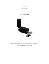
7 Two-Way Voice Communication or Music Playback via Bluetooth Headset Without
Using the PCM/I
2
S Bridge
For mobile phone designs that implement a dedicated RF IC (voice modem) for voice communication, the
PCM/I
2
S Bridge can be bypassed as long as the RF IC has an analog interface that can connect directly
to the differential inputs (CP_IN) and outputs (CP_OUT) of the LM49370.
Figure 12. Using the LM49370 with a Dedicated RF Module for Two-way Voice Communication via
Bluetooth Headset
With this type of configuration (Figure 12), the LM49370’s I
2
S port is not needed for two-way voice
communication. Incoming analog voice data from the RF voice module is sent from CP_IN to the
LM49370's ADC. After the analog to digital conversion, the incoming voice data is routed to the Bluetooth
receiver through the PCM output port. Outgoing voice data from the Bluetooth headset is sent to the
LM49370's DAC through the PCM input port. After the digital to analog conversion, the outgoing voice
data is sent to the RF voice module through the CP_OUT differential output for voice transmit.
Figure 13. Alternative Method for Two-way Voice Communication via Bluetooth
17
SNAA039A–July 2007–Revised May 2013
AN-1591 LM49370 PCM/I
2
S Bridge
Submit Documentation Feedback
Copyright © 2007–2013, Texas Instruments Incorporated

Automatic Handshaking
PCM
PCM_TX_SEL
PCM_SDO
IIR
Dec
Mono ADC
ADC_SRC_MODE
From
(AUX_L + AUX_R)
CIC
ADSM
Bluetooth Headset
Bluetooth
Transceiver
Baseband Processor
Audio Port 1
PCM (mono)
I
2
S
(MP3 content)
LM49370
802.15.1
FM or TV Tuner
Module
AUX_L AUX_R
Stereo Bluetooth Headsets
www.ti.com
The LM49370 features a set of stereo analog inputs (AUX_L and AUX_R) that can route stereo content
from a FM radio module or TV tuner module to the Bluetooth transceiver.
Figure 14. Using the LM49370 to Route FM Radio or TV Audio to a Bluetooth Headset
The analog audio content received from AUX_L and AUX_R inputs can be summed together to form a
mono signal that is then routed to the ADC. After the analog to digital conversion, the mono signal is sent
to the Bluetooth transceiver through the PCM output port.
Figure 15. FM Radio or TV Tuner Playback via Bluetooth Headset
8 Stereo Bluetooth Headsets
The LM49370 is primarily targeted for mobile phone scenarios that require the use of a mono Bluetooth
headset. For scenarios that require the use of a stereo Bluetooth headset, the Bluetooth transceiver and
baseband processor must be A2DP (Advanced Audio Distribution Profile) capable. A dedicated A2DP
data link is required between the baseband processor and Bluetooth transceiver for streaming music to a
stereo Bluetooth headset. The LM49370 can be bypassed during A2DP operation.
However, the LM49370 has built-in amplifiers to drive a wired pair of stereo headphones for non-Bluetooth
applications.
9 Revision History
Rev Date Description
1.0 07/17/07 Initial release.
18
SNAA039A–July 2007–Revised May 2013
AN-1591 LM49370 PCM/I
2
S Bridge
Submit Documentation Feedback
Copyright © 2007–2013, Texas Instruments Incorporated

IMPORTANT NOTICE
Texas Instruments Incorporated and its subsidiaries (TI) reserve the right to make corrections, enhancements, improvements and other
changes to its semiconductor products and services per JESD46, latest issue, and to discontinue any product or service per JESD48, latest
issue. Buyers should obtain the latest relevant information before placing orders and should verify that such information is current and
complete. All semiconductor products (also referred to herein as “components”) are sold subject to TI’s terms and conditions of sale
supplied at the time of order acknowledgment.
TI warrants performance of its components to the specifications applicable at the time of sale, in accordance with the warranty in TI’s terms
and conditions of sale of semiconductor products. Testing and other quality control techniques are used to the extent TI deems necessary
to support this warranty. Except where mandated by applicable law, testing of all parameters of each component is not necessarily
performed.
TI assumes no liability for applications assistance or the design of Buyers’ products. Buyers are responsible for their products and
applications using TI components. To minimize the risks associated with Buyers’ products and applications, Buyers should provide
adequate design and operating safeguards.
TI does not warrant or represent that any license, either express or implied, is granted under any patent right, copyright, mask work right, or
other intellectual property right relating to any combination, machine, or process in which TI components or services are used. Information
published by TI regarding third-party products or services does not constitute a license to use such products or services or a warranty or
endorsement thereof. Use of such information may require a license from a third party under the patents or other intellectual property of the
third party, or a license from TI under the patents or other intellectual property of TI.
Reproduction of significant portions of TI information in TI data books or data sheets is permissible only if reproduction is without alteration
and is accompanied by all associated warranties, conditions, limitations, and notices. TI is not responsible or liable for such altered
documentation. Information of third parties may be subject to additional restrictions.
Resale of TI components or services with statements different from or beyond the parameters stated by TI for that component or service
voids all express and any implied warranties for the associated TI component or service and is an unfair and deceptive business practice.
TI is not responsible or liable for any such statements.
Buyer acknowledges and agrees that it is solely responsible for compliance with all legal, regulatory and safety-related requirements
concerning its products, and any use of TI components in its applications, notwithstanding any applications-related information or support
that may be provided by TI. Buyer represents and agrees that it has all the necessary expertise to create and implement safeguards which
anticipate dangerous consequences of failures, monitor failures and their consequences, lessen the likelihood of failures that might cause
harm and take appropriate remedial actions. Buyer will fully indemnify TI and its representatives against any damages arising out of the use
of any TI components in safety-critical applications.
In some cases, TI components may be promoted specifically to facilitate safety-related applications. With such components, TI’s goal is to
help enable customers to design and create their own end-product solutions that meet applicable functional safety standards and
requirements. Nonetheless, such components are subject to these terms.
No TI components are authorized for use in FDA Class III (or similar life-critical medical equipment) unless authorized officers of the parties
have executed a special agreement specifically governing such use.
Only those TI components which TI has specifically designated as military grade or “enhanced plastic” are designed and intended for use in
military/aerospace applications or environments. Buyer acknowledges and agrees that any military or aerospace use of TI components
which have not been so designated is solely at the Buyer's risk, and that Buyer is solely responsible for compliance with all legal and
regulatory requirements in connection with such use.
TI has specifically designated certain components as meeting ISO/TS16949 requirements, mainly for automotive use. In any case of use of
non-designated products, TI will not be responsible for any failure to meet ISO/TS16949.
Products Applications
Audio www.ti.com/audio Automotive and Transportation www.ti.com/automotive
Amplifiers amplifier.ti.com Communications and Telecom www.ti.com/communications
Data Converters dataconverter.ti.com Computers and Peripherals www.ti.com/computers
DLP® Products www.dlp.com Consumer Electronics www.ti.com/consumer-apps
DSP dsp.ti.com Energy and Lighting www.ti.com/energy
Clocks and Timers www.ti.com/clocks Industrial www.ti.com/industrial
Interface interface.ti.com Medical www.ti.com/medical
Logic logic.ti.com Security www.ti.com/security
Power Mgmt power.ti.com Space, Avionics and Defense www.ti.com/space-avionics-defense
Microcontrollers microcontroller.ti.com Video and Imaging www.ti.com/video
RFID www.ti-rfid.com
OMAP Applications Processors www.ti.com/omap TI E2E Community e2e.ti.com
Wireless Connectivity www.ti.com/wirelessconnectivity
Mailing Address: Texas Instruments, Post Office Box 655303, Dallas, Texas 75265
Copyright © 2013, Texas Instruments Incorporated
/