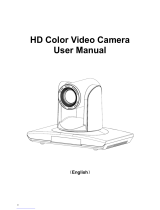
VADDIO RoboSHOT 30 Installation and User Manual

Category
Security cameras
Type
Installation and User Manual

This manual is also suitable for

© 2015 Vaddio - All Rights Reserved. RoboSHOT Cameras for AV Bridge MATRIX PRO - Document Number 342-1027 Rev A
VADDIO ROBOSHOT™ SERIES CAMERAS
RoboSHOT 12 and RoboSHOT 30, High Definition Robotic PTZ
Camera Systems for use with
The AV Bridge MATRIX PRO
A
V Bridge MATRIX PRO
(Sold Separately)
System Model and Part Numbers
RoboSHOT 12 System, 999-9900-500 (Worldwide)
RoboSHOT 30 System (black camera), 999-9910-500 (Worldwide)
RoboSHOT 30 System (white camera), 999-9910-500W (Worldwide)
RoboSHOT 30
High-definition Robotic PTZ Camera for Medium to Large Venue
s
Featuring 30X Optical Zoom Lens and Tri-Synchronous Motion
.
A
vailable in Black or White finishes.
RoboSHOT 12
High-definition Robotic PTZ Conferencing Camera
Featuring a 12X, 73º Wide Angle Optical Zoom Lens
and Tri-Synchronous™ Motion
Installation and User Guide
RoboSHOT HD Cameras for MATRIX PRO
RoboSHOT HD Cameras for MATRIX PRO - Document Number 342-1027 Rev A Page 2 of 41
Inside Front Cover Page - Almost Blank
RoboSHOT HD Cameras for MATRIX PRO
RoboSHOT HD Cameras for MATRIX PRO - Document Number 342-1027 Rev A Page 3 of 41
TABLE OF CONTENTS
Overview ...................................................................................................................................................................................... 4
Unpacking the Camera Systems .................................................................................................................................................. 6
Purpose of this Manual ............................................................................................................................................................. 6
Image: RoboSHOT 12 HD PTZ Camera ............................................................................................................................. 7
Image: RoboSHOT 30 HD PTZ Camera ............................................................................................................................. 8
Image: RoboSHOT 12 and 30 Rear Panel Connections ..................................................................................................... 9
Getting Started ........................................................................................................................................................................... 10
Setting the RoboSHOT Camera HD Resolution ..................................................................................................................... 10
Drawing: DIP Switch and Resolution Label on the Bottom of the RoboSHOT ................................................................... 10
Setting the RoboSHOT Switch Gear: ..................................................................................................................................... 10
DIP Switch Settings Further Explained (DSSFE): .................................................................................................................. 10
Diagram: Basic Wiring Configuration with MATRIX PRO .................................................................................................. 11
Pre-Installation ........................................................................................................................................................................... 11
Installation Basics: .................................................................................................................................................................. 12
System Wiring ........................................................................................................................................................................ 12
Controlling the Camera .............................................................................................................................................................. 13
IR Remote Commander ..................................................................................................................................................... 13
Telnet Control ..................................................................................................................................................................... 13
The Screen Shot Tour ................................................................................................................................................................ 14
Compatible Web Browsers ..................................................................................................................................................... 14
DHCP IP Set-up (Dynamic Host Configuration Protocol) ....................................................................................................... 14
Static IP Set-up: ..................................................................................................................................................................... 14
Screen Shot: Login ............................................................................................................................................................ 14
Screen Shot:
Camera Control Page .................................................................................................................................. 15
Screen Shot: Storing Presets ............................................................................................................................................ 16
Screen Shot: Admin login from the Camera Control Page ................................................................................................ 17
Screen Shot: Admin Menu - Camera Settings ................................................................................................................... 18
Screen Shot: Admin Menu - Room Labels ........................................................................................................................ 19
Screen Shot: Admin Menu - DHCP Network Configuration ............................................................................................... 20
Screen SHOT: Admin Menu - Static IP Configuration ....................................................................................................... 20
Screen SHOT: Admin Menu - Security .............................................................................................................................. 21
Screen Shot: Admin Menu - Diagnostics ........................................................................................................................... 21
Screen Shot: Admin Menu - System ................................................................................................................................. 22
Screen Shot: Admin Menu - Update Confirmation ............................................................................................................. 23
Screen Shot: Admin Menu - Update in Progress ............................................................................................................... 23
Screen Shot - Admin Menu - Help ...................................................................................................................................... 24
General Specifications ............................................................................................................................................................... 25
Communication Specification ..................................................................................................................................................... 26
Command Setting Values ........................................................................................................................................................... 31
Exposure Control.................................................................................................................................................................... 31
Telnet Serial Command API ....................................................................................................................................................... 32
Telnet Command List ............................................................................................................................................................. 32
Compliance and CE Declaration of Conformity - RoboSHOT HD PTZ Cameras ....................................................................... 38
Warranty Information .................................................................................................................................................................. 39
RoboSHOT HD Cameras for MATRIX PRO
RoboSHOT HD Cameras for MATRIX PRO - Document Number 342-1027 Rev A Page 4 of 41
O
VERVIEW
The impressive RoboSHOT HD PTZ are professional cameras with
very high quality imaging, fine detail and exceptional color
reproduction. This camera offers integrators, dealers and end users
an incredible improvement over other conferencing and large venue
cameras available today. The RoboSHOT Platform consists of two
models; the RoboSHOT 12 and the RoboSHOT 30. These
RoboSHOT systems are specifically packaged for use with the AV
Bridge MATRIX PRO and takes advantage of the three (3) built-in
Quick-Connect systems with in the MATRIX PRO.
The RoboSHOT 12 is perfect for small to medium sized conference
rooms. This model features a 12X optical zoom and a 73° wide angle
horizontal field of view, which provides incomparable support for
applications including UCC Applications, videoconferencing, distance
learning, lecture capture, telepresence and more!
The RoboSHOT 30 camera performs brilliantly in medium to large
rooms. It features a 30X optical zoom with an impressive 2.3° tele end
to 65° wide end horizontal field of view and provides exceptional
support for applications including House of Worship productions, large
auditorium A/V systems, large distance learning classrooms, live event
theatres with IMAG systems, large lecture theatres with lecture capture
and more!
The key features of both RoboSHOT cameras are Tri-Synchronous
Multi-Axis Motion and the Advanced Image Sensor, lens and ISP
(image signal processor) combination. The Tri-Synchronous Motion
algorithm in the RoboSHOT cameras is capable of moving all three
(pan, tilt and zoom) axes simultaneously. The algorithm calculates the
position and velocity of the smooth, direct-drive motor movements
between the presets so pan, tilt and zoom arrive at the preset subject
simultaneously, which finally allows for smooth and manageable on-air
camera movements. Yep, there’s no more pan/tilt, then zoom like other
PTZ cameras available today.
The lens, image sensor and ISP are the real magic behind
the RoboSHOT’s remarkable video performance
characteristics. Both cameras use the latest generation
Exmor® 1/2.8”, 2.38 Megapixel, Full HD (1080p/60) high-
speed, low noise CMOS image sensor combined with a
new ISP, produces vivid, realistic and accurate color with
extremely fast, razor sharp automatic focus and auto iris
routines.
The RoboSHOT platform, paired with the MATRIX PRO, uses the Vaddio EZCamera™ Cat-5 Cable System to
transport HSDS™ (differential video), power and control to and from the camera over Cat-5/5e/6 cables. Three
Quick-Connect interfaces are built-into the MATRIX PRO and with the RoboSHOT cameras, distances of 100’
(30.48m) are achievable in FULL HD at 1080p/60.
All RoboSHOT’s are equipped with an Ethernet port and a built-in web server, which allows the user to control the
camera functions on an internal web page with a browser from anywhere in the world, or in the same room, over
the IP network. Telnet, IR Remote and RS-232 control for the camera are available to satisfy almost any system
control requirements.
The RoboSHOT cameras and the AV Bridge MATRIX PRO were designed for the times and represent a new era
in specifying and integrating professional quality cameras into A/V and conferencing system configurations. In
short, it has never been easier to integrate cameras into any environment than with these products.
RoboSHOT 30
HD PTZ Camera on Mount
RoboSHOT 12
HD PTZ Camera on Mount
A
V Brid
g
e MATRIX PRO
RoboSHOT HD Cameras for MATRIX PRO
RoboSHOT HD Cameras for MATRIX PRO - Document Number 342-1027 Rev A Page 5 of 41
Intended Use:
Before operating the device, please read the entire manual thoroughly. The system was designed, built and tested
for use indoors with the power supply provided. The use of a power supply other than the one provided or outdoor
operation hasn’t been tested and may damage the device and/or create an unsafe operating condition.
Save These Instructions:
The information contained in this manual will help you install and operate your product. If these instructions are
misplaced, Vaddio keeps copies of Specifications, Installation and User Guides and most pertinent product
drawings (DWG and PDF) for the Vaddio product line on the Vaddio website. These documents can be downloaded
from www.vaddio.com free of charge.
Important Safeguards:
Read and understand all instructions before using. Do not operate any device if it has been dropped or damaged.
In this case, a Vaddio technician must examine the product before operating. To reduce the risk of electric shock,
do not immerse in water or other liquids and avoid extremely humid conditions.
The RoboSHOT HD PTZ camera connectivity for all signals (video, power and control) is over Cat-5/5e/6 cable
(ubiquitously referred to as Cat-5 or Cat-5e). For best results, please use quality Cat-5e cable and real RJ-45
crimpers. Unlike phone and data lines that use the four center conductors (pairs 3 & 6 and pairs 4 & 5), the Vaddio
EZCamera systems use all of the pins in most configurations. When terminated correctly The Vaddio Cat-5e
solution provides for the utmost in flexibility for HD video system design, integration and ease of installation.
Use only the power supply provided with the system. Use of any unauthorized or
extended DC power supplies will void any and all warranties.
Please do not use “pass-thru” type RJ-45 connectors. These pass-thru type
connectors do not work well for professional installations and can be the cause of
intermittent connections which can result in the RS-232 control line failing and
locking up, and/or compromising the HSDS (high speed differential signals). For
best results please use standard RJ-45 connectors and test all cables for proper
pin-outs prior to use and connection to Vaddio Cat-5e products.
RoboSHOT HD Cameras for MATRIX PRO
RoboSHOT HD Cameras for MATRIX PRO - Document Number 342-1027 Rev A Page 6 of 41
U
NPACKING THE
C
AMERA
S
YSTEMS
Carefully remove the product and all of the included parts from the packaging.
Identify the following parts for each camera:
RoboSHOT 12 System for AV Bridge MATRIX PRO
Part Number 999-9900-500 (Worldwide)
One (1) RoboSHOT 12 HD PTZ Camera (998-9900-000)
One (1) Thin Profile Wall Mount (535-2000-240) with Mounting Hardware
One (1) IR Remote Commander (998-2100-000)
One (1) Quick Setup Guide
Notes:
No other peripherals are included.
MATRIX PRO is Sold Separately.
Full manuals are downloaded from support.vaddio.com
RoboSHOT 30 System for AV Bridge MATRIX PRO
Part Number 999-9910-500 (Worldwide)
One (1) RoboSHOT 30 HD PTZ Camera (998-9910-000 in black)
One (1) Thin Profile Wall Mount (535-2000-240) with Mounting Hardware
One (1) IR Remote Commander (998-2100-000)
One (1) Quick Setup Guide
Notes:
No other peripherals are included.
MATRIX PRO is Sold Separately.
Full manuals are downloaded from support.vaddio.com
RoboSHOT 30 System for AV Bridge MATRIX PRO
Part Number 999-9910-500W (Worldwide)
One (1) RoboSHOT 30 HD PTZ Camera (998-9910-000 in white)
One (1) Thin Profile Wall Mount (535-2000-240W - white, not shown) with Hardware
One (1) IR Remote Commander (998-2100-000)
One (1) Quick Setup Guide
Notes:
No other peripherals are included.
MATRIX PRO is Sold Separately.
Full manuals are downloaded from support.vaddio.com
Purpose of this Manual
This manual will concentrate on the RoboSHOT cameras, how they’re connected to the MATRIX PRO, the key
features, the specifications, etc…, so it may seem a little brief at first, but brief can be good thing? Please use this
manual in conjunction with the MATRIX PRO manual for the rest of the story. Now, for the easy part.
RoboSHOT HD Cameras for MATRIX PRO
RoboSHOT HD Cameras for MATRIX PRO - Document Number 342-1027 Rev A Page 7 of 41
Image: RoboSHOT 12 HD PTZ Camera
Camera Front View with Feature Call-outs
1) Camera and Zoom Lens: This RoboSHOT model features a 12X optical zoom lens (12X in Super-Wide mode
and 10X in normal mode) that is built around an Exmor 1/2.8-Type, high-speed, low noise image sensor with a total
of 2.38 megapixels (2.14 effective megapixels) for exceptionally precise HD video image acquisition in a small to
medium sized conference room.
2) Camera Support Arm: The RoboSHOT cameras use a single control arm for pan and tilt movements. Both
ends of the cast control arm are anchored with silent and smooth BLDC (brushless DC) direct drive motors. These
motors provide ultra-accurate and fast camera positioning and are capable of the slowest of crawls, which are
suitable for on-air use.
3) IR Sensors: IR sensors are built into the front of the RoboSHOT to receive IR signals from the IR Remote
Commander supplied with the camera. The IR sensors sit behind the Makrolon IR Window on the front of the base.
4) Multi-Color LED:
The multi-colored LED indicates the use states of the camera:
Purple LED is for Boot-up and Standby modes.
Blue LED is for normal operation and is a power on, ready condition.
The blue LED will blink when the camera receives a valid IR command.
Solid red LED is to indicate a tally function illuminating when the camera is on-air.
Blinking red LED indicates a fault condition.
Yellow LED illuminates during a firmware update.
5) Logo: Really Cool Logo Badge (RCLB) is located on the IR Window.
6) Camera Base: Cast zinc alloy base for strength and stability, powder coated for toughness with fine texture.
Color: Silver and Black
RoboSHOT HD Cameras for MATRIX PRO
RoboSHOT HD Cameras for MATRIX PRO - Document Number 342-1027 Rev A Page 8 of 41
Image: RoboSHOT 30 HD PTZ Camera
The differences between the 12X model and the 30X models center around the power of the optical zoom lens and
overall color of the camera models. The 30X is available in both black and white.
1) Camera and Zoom Lens: This RoboSHOT model has a powerful 30X optical zoom lens that is built around
an Exmor 1/2.8-Typ, high-speed, low noise image sensor with a total of 2.38 megapixels (2.14 effective megapixels)
for vibrant, detailed HD video image acquisition in a large to medium sized room.
2) Camera Support Arm: The RoboSHOT cameras use a single control arm for pan and tilt movements. Both
ends of the cast control arm are anchored with silent and smooth BLDC (brushless DC) direct drive motors. These
motors provide ultra-accurate and fast camera positioning and are capable of the slowest of crawls, which are
suitable for on-air use.
3) IR Sensors: IR sensors are built into the front of the RoboSHOT to receive IR signals from the IR Remote
Commander supplied with the camera. The IR sensors sit behind the Makrolon IR Window on the front of the base.
4) Multi-Color LED:
The multi-colored LED indicates the use states of the camera:
Purple LED is for Boot-up and Standby modes.
Blue LED is for normal operation and is a power on, ready condition.
The blue LED will blink when the camera receives a valid IR command.
Solid red LED is to indicate a tally function illuminating when the camera is on-air.
Blinking red LED indicates a fault condition.
Yellow LED illuminates during a firmware update.
5) Logo: Really Cool Logo Badge (RCLB) is located on the IR Window.
6) Camera Base: Cast zinc alloy base for strength and stability, powder coated for toughness with fine texture.
Available in Black or White Versions
RoboSHOT HD Cameras for MATRIX PRO
RoboSHOT HD Cameras for MATRIX PRO - Document Number 342-1027 Rev A Page 9 of 41
Image: RoboSHOT 12 and 30 Rear Panel Connections
Rear panel connections are identical for both models (RoboSHOT 12 shown).
1) CAMERA SETTINGS: DIP switch settings for IR remote frequency, baud rate and image flip can be configured
on these switches. See the Switch Settings page for additional information.
2) HD VIDEO SELECT: A rotary switch allows the user to choose the HD video output resolution. See the Switch
Settings page for additional information.
3) NETWORK CONTROL Port: The Ethernet 10/100 port allows the camera to be controlled from embedded
web server with a web browser or through Telnet session.
4) RS-232 Port (Color Coded Blue): The RS-232 port accepts modified VISCA protocol for camera control over
a Cat-5e cable.
5) EZ-POWER VIDEO Port (Color Coded Orange and Yellow): The EZ-Power Video port supplies 24 VDC
power to the camera and delivers HD video back to the Quick-Connect interface using high speed differential
signaling over Cat-5e cable. Color coded orange for use with Quick-Connect SR, DVI/HDMI-SR, USB and USB
Mini. Color code yellow is for use with the Quick-Connect Universal CCU.
6) 36 VDC FOR CCU ONLY (Color Coded Red): Not Used with MATRIX PRO - The CCU power port is only
used with Quick-Connect Universal CCU and is shipped with a label over the connectors to remind the installer to
“Please test and mark the Cat-5/5e/6 UTP cable and confirm the connectivity prior to termination”.
RoboSHOT HD Cameras for MATRIX PRO
RoboSHOT HD Cameras for MATRIX PRO - Document Number 342-1027 Rev A Page 10 of 41
IR 1
1 & 2 UP
ON
DIP SWITCH SETTINGS
8
12
3
4
567
HD VIDEO RESOLUTION SELECT
720p/59.94
1080i/59.94
0
1
2
3
4
5
6
7
8
9
A
B
C
D
E
F
1080p/59.94
1080i/60
1080p/60
720p/50
21
5
4
3768
IR 2
ON
IR 3
ON
IR
OUT
OFF
BAUD
9600
bps
38,400
bps
1080i/50
1080p/50
7
OFF
8
OFF
IMAGE
FLIP
OF
F
ON
SUPER
WIDE
OFF
ON
720p/60
720p/30
1080p/30
720p/25
1080p/25
GETTING STARTED
Setting the RoboSHOT Camera HD Resolution
The RoboSHOT cameras control the resolution of the video signal sent back to the Quick-Connect interface. There
is, as explained earlier, a rotary switch to set the HD video resolution and a set of eight (8) DIP switches that
determine certain camera functions.
Drawing: DIP Switch and Resolution Label on the Bottom of the RoboSHOT
Setting the RoboSHOT Switch Gear:
- Set the desired and available HD output resolution for the camera with the Rotary Switch.
- Set the IR control frequency of the camera if it is to respond to the IR remote control.
- IR OUT is not used with MATRIX PRO.
- If inverting the camera, turn the IMAGE FLIP ON (SW4).
- For the RoboSHOT 12X model only, set the Super-wide mode to ON for a 12X, 73º horizontal super-wide
angle of view. Normal mode will produce 67.2º horizontal field of view (HFOV). The RoboSHOT 30 does not have
a Super Wide mode.
- Set the Baud Rate DIP switch (SW6) to 9600bps for most applications. Default is 9600 bps systems.
- Setting all DIP switches DOWN with a power cycle loads the default camera settings. Return DIPs to
desired operating position after power cycle
.
Note: Switches 7 & 8 are reserved for future use.
DIP Switch Settings Further Explained (DSSFE):
IR 1, 2 and 3 (SW 1 &2): A single IR remote has the capability of operating up to three different PTZ cameras
in a room. Use these selector DIP switches and the selector buttons at the top of the IR remote to select the
frequency.
IR OUT on/off (SW3): The IR output is not used with the MATRIX PRO. However, if certain lighting or other
pesky IR sources are within a room effect the performance of the camera and RS-232 is the only control being
used, then turn SW3 to IR OUT ON, which turns of the IR reception of the camera’s internal processor.
Image Flip (SW4): To invert the camera, turn the IMAGE FLIP ON (switch down).
Super-Wide Mode: Super-wide works only with the RoboSHOT 12 model and allows the camera to switch
from 67.3º wide end HFOV to a Super Wide 73º wide end HFOV.
Baud Rate (SW6): The options for baud rate are either 9600 or 38,400 bps. The 9600 bps works best with
Cat-5e over distance. Use 38,400 bps for short control lines only.
DIP Switches (SW7 & 8): Not used for operation, please leave these DIP switches up or in the OFF position.
All Down
with Power
Cycle for
Defaults
RoboSHOT HD Cameras for MATRIX PRO
RoboSHOT HD Cameras for MATRIX PRO - Document Number 342-1027 Rev A Page 11 of 41
Diagram: Basic Wiring Configuration with MATRIX PRO
RoboSHOT 12 cameras with AV Bridge Matrix PRO showing basic connectivity with color coded RJ-45 jacks.
Obviously, there’s a whole bunch more stuff going on here with the MATRIX PRO, that’s why we suggested earlier
that using the MATRIX PRO manual in conjunction with this manual for the RoboSHOT’s is your best bet.
P
RE
-I
NSTALLATION
Choose camera mounting location, paying close attention to camera viewing angles, lighting conditions, possible
line of site obstructions, and checking for in-wall obstructions where the camera is to be mounted. Always pick
a mounting location that will optimize the performance of the camera. Please locate the camera to enable easy
positioning of the camera body with the ability to point down and away from the ceiling and a pile of fluorescent
lighting cells. Cameras generally don’t like to be swamped with fluorescent light and nobody sits or stands on
the ceiling anyway...as a general rule.
For Power/Video and RS-232 signals, use standard Cat-5/5e/6 cable (568B termination and real RJ-45
connectors) from the EZ-POWER VIDEO and RS-232 ports on the back of the RoboSHOT to the MATRIX PRO.
These jacks are color coded for ease of connection.
HDMI Out to Monitor
Simulated
Video Feed
Key:
RS-232 Cat-5
Blue Line
Bidirectional RS-232 Control
Signals
Orange Line
EZ-POWER VIDEO Cat-5
Power to Camera and differential
HD Video from the Camera
Cat-5 Cable
Distance for RoboSHOT video,
power and control is up to 100’
RS-232
Cat-5
RS-232 Cat-5
EZ-POWER
VIDEO Cat-5
EZ-POWER
VIDEO Cat-5
RoboSHOT 12
HD PTZ Cameras
AV Bridge MATRIX PRO
Rear Panel Connections
HD Video Monitor
RoboSHOT HD Cameras for MATRIX PRO
RoboSHOT HD Cameras for MATRIX PRO - Document Number 342-1027 Rev A Page 12 of 41
More Notes: Use of pass-thru type RJ-45 connectors is highly discouraged. The Vaddio Cat-5 wiring
standard uses pins 1, 2, 7 and 8 on both the power/video and the control Cat-5e cables. The pass-through
connectors have proven to provide insufficient connectivity for these important signals. They are OK for
voice and data that use the center pins only, but not for cabling systems that use all the pins.
Installation Basics:
The RoboSHOT cameras include a Thin Profile Wall Mount for…wall mounting the camera. There
are options for IN-Wall™ mounts and IN-Ceiling™ Half-Recessed as well. The Cat-5 cabling
ideology is especially convenient for camera mounting when the camera location is not anywhere
near an AC outlet. Installation is simplified in that no custom 8-Pin mini-din cables or expensive
plenum coax cables or multi-pin cables or power outlets are required near the camera location. All
Cat-5 cabling is routed to the head-end using with standard straight through RJ-45 connectors
(568B termination). “Pass-thru” type RJ-45 connectors should be avoided, like a bad cliché.
Determine Camera Mount Location and Mount
After determining the optimum location of the camera system, route the required Cat-5e cables from the camera to
the head-end Quick-Connect. Test and mark the Cat-5e cables: EZ-POWER VIDEO and RS-232.
The Cat-5e cables should feed-through the cable management slots provided by
all Vaddio mounting options. If the wall mount is to be mounted on a 2-gang wall
box, use the screws supplied with the wall box cover plate to attach the Thin
Profile Wall Mount Bracket. If mounting to drywall with wall anchors, use the four
(4) quality wall anchors and screws provided.
The mounting holes are slotted and are 90° opposing to provide easy leveling.
Level the mount and place the camera on the mount. Connect the marked and
tested Cat-5e cables to the appropriate RJ-45 jacks. Check the level again to
avoid any of those weird Batman camera angles. Use the provided ¼”-20 x .375
mounting screw to attach the Camera to the mount.
System Wiring
Follow the sample wiring diagram (page 11) for connecting the Cat-5e cables to the camera and Quick-Connect
Interface. Additional diagrams are available on the Vaddio website.
Connect the RoboSHOT camera side as follows:
Connect the EZ-POWER VIDEO Cat-5 to the EZ-POWER VIDEO RJ-45 connector on the RoboSHOT.
Connect the RS-232 control Cat-5 to the RS-232 RJ-45 on the RoboSHOT.
Connect the MATRIX PRO side as follows:
Connect the RS-232 Cat-5 cable to the RS-232 connector on the MATRIX PRO.
Connect the EZ-POWER VIDEO Cat-5e to the EZ-POWER VIDEO RJ-45 connector on the MATRIX PRO.
Note: Please check all Cat-5 cables for continuity in advance of final connection (568B). Plugging the
EZ-POWER/VIDEO Cat-5 cable into the wrong RJ-45 or using the wrong pin-out may cause damage
to the camera system and void the warranty!
Power Up
Connect the power supply provided with the MATRIX PRO and Plug the AC side into an AC outlet (thanks Captain
Obvious). Power will travel down the EZ-POWER VIDEO Cat. 5 cable to the camera. The camera will boot up and
in a few seconds and initialize the pan/tilt motors. The MATRIX PRO will auto-identify the camera and load the
specific control protocols for the camera, HSDS (differential) video will travel back down the Cat-5 cable and be
ready to accept control information from MATRIX PRO.
Use a level to
level the mount…
RoboSHOT HD Cameras for MATRIX PRO
RoboSHOT HD Cameras for MATRIX PRO - Document Number 342-1027 Rev A Page 13 of 41
C
ONTROLLING THE
C
AMERA
IR Remote Commander
The following functions are accessible with the Vaddio IR remote:
Camera Power On/Off (Toggle on/off same button)
Back Light Compensation (Toggle on/off same button)
Data Screen: Toggle on/off the OSD for the RoboSHOT’s IP/MAC Address
Camera Select (the remote can operate 3 cameras (with 3-IR Freq.)
Pan/Tilt and Home controls with Reverse and Std. Pan direction
Pan/Tilt Reset
Auto Focus (Toggle on/off same button)
Zoom In/Out controls Wide & Telephoto
Fast speed controls (W & T)
Slow speed controls (W & T)
Manual Focus On/Off control (Toggle on/off same button)
Near (-) adjustment
Far (+) adjustment
Six (6) pan/tilt/zoom positioning presets (1 through 6)
Preset Set (store)
Preset Reset (clear)
Red LED that indicates IR Transmission and battery level
The IR Remote operational characteristics are as follows:
Preset Activation: IR Remote is limited to executing Presets 1 through 6
Tri-Sync Speed on Preset: If a global Tri-Sync speed is stored in the preset by the user/admin, then that
speed is used. If no Tri-Sync speed is assigned, then a default (medium) speed will be used.
Preset Store: IR Remote is limited to positional (PTZ) type presets. To set a preset, position the camera,
hold down the Preset Button and touch the one of the preset numbered buttons 1 through 6.
Telnet Control Examples
The RoboSHOT cameras have *Telnet capability on board, however please use the Telnet
command list within the MATRIX PRO to control the camera. Nevertheless, the following
*Telnet commands are available through the Camera’s Ethernet Port.
Camera Home
Camera Pan (left, right and speed - real-time operation)
Camera Tilt (up, down and speed - real-time operation)
Camera Zoom (zoom in/out/stop and speed - real-time operation)
Camera Store Preset (Gets or Sets 12 presets with global relative PTZ [Tri-Sync] speed control to destination)
Camera Image (Gets or sets current image control values, sets in 1 of 3 CCU presets, AWB or manual
w/Red and Blue gain, BLC on/off, Auto Iris or manual with Iris value and Gain, Detail and Chroma)
Camera Standby (Gets or sets standby power mode - camera has to us less power in this mode)
Exit (ends Telnet session)
Help (displays CLISH syntax)
History (command history)
Network Ping (send ICMP ECHO_RE
QUEST to network hosts)
Network Settings (Gets MAC address, IP address, Subnet Mask, Gateway and NTP server address)
System Factory Reset
System Reboot
Version (system version information)
*Please see the full and actual Telnet command list at the end of this manual for details.
Vaddio
IR Remote
Commander
RoboSHOT HD Cameras for MATRIX PRO
RoboSHOT HD Cameras for MATRIX PRO - Document Number 342-1027 Rev A Page 14 of 41
T
HE
S
CREEN
S
HOT
T
OUR
The RoboSHOT camera platform uses a Linux OS and has a built-in web server for configuration and control from
a web browser via an Ethernet network connection. These web pages will allow the user or administrator to control
the camera, set PTZ presets, set security passwords, change the IP address, view diagnostics, access the firmware
upgrade page and more!
Compatible Web Browsers
You may ask, “What are the approved web browsers that work with the RoboSHOT’s embedded web server?”
Chrome
®
(latest version), Firefox
®
(latest version), Internet Explorer
®
(versions 8 through 11) and Safari
®
(versions
6 and 7) have been tested thoroughly with RoboSHOT and are compatible.
DHCP IP Set-up (Dynamic Host Configuration Protocol)
DHCP Set-up (skip this section if Static IP). If the LAN has a DHCP (dynamic host configuration protocol) server, then the IP address,
gateway and routing information will automatically be assigned. The software is defaulted to DHCP and will attempt to dynamically obtain an
IP address using DHCP, but it will fall back to the default address of (169.254.1.1) if no DHCP server can be found.
Static IP Set-up:
The static IP can be assigned either through the network or directly to a computer using a cross-over cable. Depending on the age of the
computer, you may not need a cross-over cable. Either way the steps are the same for network or direct connection to a computer. The default
address of the camera is 169.254.1.1 and the Subnet mask is 255.255.0.0. Different computer OS types all have their own way of doing things
(without question), but they are essentially doing the same stuff, changing the IP address so the web pages of the RoboSHOT are accessible
.
Screen Shot: Login
The RoboSHOT webserver is intended as a user’s camera control page at one level, and an administrator’s
management tool at another level, which requires password authentication for access.
The Login Page will appear if there is a user name assigned by the administrator. Assigning a user name can limit
access to the admin menus by a general user.
By default, the User name is: user, and the password for the User account is: password.
The Administrator can set the name and password for the User account.
By default, the Admin user name is: admin, and the password for the admin account is: password.
If a user or an admin logs in through this screen, then the next page shown will be the camera control page.
The user will only have access to the camera control page.
The Admin will have complete access to all web pages.
RoboSHOT HD Cameras for MATRIX PRO
RoboSHOT HD Cameras for MATRIX PRO - Document Number 342-1027 Rev A Page 15 of 41
Screen Shot: Camera Control Page
This web page provides access to the camera controls for the User and the Admin.
1) Pan, Tilt and Home Controls: These intuitive controls use the up/down and diagonal arrows for camera pan and tilt. The
center button will move the camera to the home position.
2) Zoom Control: The camera’s zoom lens can be controlled with the “+” to zoom-in and the “-“to zoom out.
3) Pan/Tilt and Zoom Speed Controls: The speed for both the Pan/Tilt and Zoom controls can be adjusted with the three
(3) sliders in this section. For tighter shots, it is recommended that the slower speed is used. These controls are for real-
time camera movements only.
4) Standby: The Standby control puts the camera in low power mode and effectively puts the RoboSHOT to sleep. The
camera will pan 90º from center and 30º downward (to not collect dust on the lens). When the camera is inverted (ceiling
mounted) the camera will pan 90º from center and 30º downward. If the system is on, then the button will be blue and
controls will be visible. If the button is red, no controls are accessible and the screen states: Device is in standby. Click
to power-up, then you’ll know what to do.
5) Camera Presets: Twelve (12) camera position presets can be recalled simply by clicking a preset number.
6) Store Preset Button: Clicking the Store button opens up a Store Preset pop-up dialog box. To set presets, set up the
camera shot, click on choice of preset number (1 through 12). The preset is stored and the dialog box closes. The Store
Preset dialog bow will prompt the operator to enter the Tri-Sync speed to the stored camera preset and if the current color
settings are to be stored with the preset too (see the next page).
7) CCU Scenes: The user has access to the CCU scenes set and stored on the Admin pages. There are three (3) user
definable presets and six (6) presets preconfigured by the technical folks at Vaddio (really Scott set them all) that are meant
to be used in certain lighting scenarios. These lighting presets included: Automatic, Incandescent Hi, Incandescent Lo,
Fluorescent Hi, Fluorescent Lo and Outdoor.
8) Administration Menu: By clicking on the Administration menu bar, the Admin Login screen will appear.
RoboSHOT HD Cameras for MATRIX PRO
RoboSHOT HD Cameras for MATRIX PRO - Document Number 342-1027 Rev A Page 16 of 41
Screen Shot: Storing Presets
1) Store Preset: When the Store Preset button is clicked (point 6 on previous page), the Store Preset dialog pops into
existence. To save the current camera shot, click one of the Preset buttons (1 through 12), the button will be
highlighted and the dialog box will present the Tri-Sync controls and if the CCU setting are to be kept with the preset.
2) Save with Tri-Sync and Setting the Tri-Sync Speed: The Tri-Synchronous Motion algorithm in the RoboSHOT
cameras is capable of moving all three (pan, tilt and zoom) axes simultaneously. The algorithm calculates the PTZ
position so pan, tilt and zoom start at the same time and arrive at the preset subject simultaneously. Tri-Sync speed
is speed at which all other presets will use to get to the preset being stored. All axes will launch at the same time
and if the next preset position is not too close or too far, axes should simultaneously arrive at the preset location.
Storing the preset with Tri-Sync is fairly straight forward. Here’s a quick method to set Tri-Sync:
a) Position the first preset, click on Store Preset and click on Preset 1. Check the Save with Tri-Sync box. Move
the tri-Sync speed slider to about the approximate position above (about 1/3 up the speed scale). This is the
speed that all the other presets will use to get to this Preset 1. The speed is stored with the destination preset.
Click on Save to store the camera location and Tri-Sync speed.
b) Set another camera position, and try a different pan, tilt and zoom position and click on Store Preset. Click on
Preset 2 through 12, click on the Save with Tri-Sync box and set the slider to about ½ way this time and click on
Save. These two presets are stored with different preset destination speeds.
c) Click between these two recently stored presets and note the different speeds applied to the 2 presets.
Tri-Sync Notes: If a preset is very close to the previous preset, like within10º with no change in zoom, it certainly
doesn’t need to be Tri-Sync’d. If a preset is super-fast and off-air, Tri-Sync won’t be of much use either. Tri-Sync
is a cool tool to set for on-air shots, but the process of setting the speeds will need some practice.
3) Store with Current Color Settings: To save the currently assigned CCU scenes settings, check this box.
4) Click Save or Cancel to exit this pop-up dialog box.
RoboSHOT HD Cameras for MATRIX PRO
RoboSHOT HD Cameras for MATRIX PRO - Document Number 342-1027 Rev A Page 17 of 41
Screen Shot: Admin login from the Camera Control Page
On the security page, which will be reviewed at a bit later in the tour, allows the Admin to set the system to allow
automatic guest access to the main camera control page. If guest access is turned on by the Admin, then system
will open to the camera control page and an additional Admin Login is provided.
The default Admin password is: password.
Admin
RoboSHOT HD Cameras for MATRIX PRO
RoboSHOT HD Cameras for MATRIX PRO - Document Number 342-1027 Rev A Page 18 of 41
Screen Shot: Admin Menu - Camera Settings
Once the Admin logs in, then all the admin menu buttons appear on the left side of the screen. The first menu
after Camera Controls is Camera Settings.
1) Load Preset at Startup: Check this box to move the camera to a predefined preset location when the camera
powers up. Use the pull down menu to select the Preset 1 through 12 to be loaded when this box is checked.
2) Load CCU Scene at Startup: Check this box to load a CCU Scene into the camera when the camera powers
up. The pull down menu will allow the selection of one of the 6-factory scenes, or one of the 3 custom scenes.
3) CCU Scenes: Click on any of these 9 buttons to load one of the CCU scenes into the camera. These Scenes
can be fine-tuned if changes are needed, and stored into any of the three User defined scenes.
4) Color Settings: When painting or shading camera scenes for specific lighting situations or environments,
these parameters can be adjusted for matching cameras in the same area. The parameters within the Color
Settings section are defined below (top to bottom):
Auto Iris Check Box: When checked, the camera will operate in Auto Iris mode, when unchecked, the
camera will be in Manual Iris mode and allow adjustment of Iris and Iris Gain levels.
3
RoboSHOT HD Cameras for MATRIX PRO
RoboSHOT HD Cameras for MATRIX PRO - Document Number 342-1027 Rev A Page 19 of 41
Iris: Move adjustment slider as required to adjust the iris opening. A numeric value will be displayed in the
box to the right of the slider.
Gain: Move adjustment slider as required for amount of iris gain desired. Numeric value will be displayed
in the box to the right of the slider.
Auto White Balance check box: When checked, camera will operate in Auto White Balance mode, when
unchecked camera will be in Manual White Balance Mode and allow for adjustment of Red and Blue Gain.
Red Gain: Move the adjustment slider as required for amount of Red Gain desired. A numeric value
will be displayed in the box to the right of the slider.
Blue Gain: Move the adjustment slider as required for amount of Blue Gain desired. Numeric value
will be displayed in the box to the right of the slider.
Back Light Compensation: When checked, Back Light Compensation will be applied to the camera if
camera is in Auto White Balance mode.
Detail: Move the adjustment slider as required for amount of detail (Aperture) desired. A numeric value
will be displayed in the box to the right of the slider. Note: If the detail is too high, the video can look grainy
and appear noisy too.
Chroma: Move the adjustment slider as required for the amount of Chroma (Color Vibrancy) desired. A
numeric value will be displayed in the box to the right of the slider.
5) Store CCU Scene button: Once the desired scene adjustments have been
made, this button will activate a pop-up menu that can be used to store this scene
into one of the three User Defined Scene locations. These User Defined Scenes
can be named as required for clarity. These User Defined CCU Scenes can be
adjusted and re-saved at any time.
6) Custom CCU Scene Labels: The labels for the (3) User Defined customizable Scenes can be changed as
needed. Mouse the cursor into the appropriate window and edit the text. Press Save to store these changes
or press Cancel to exit this window.
7) Global Preset Non-Tri-Sync Speeds: When Tri-Sync Presets are not being used, then this section governs
the pan, tilt and zoom speeds between the camera presets. These will be defaulted to a nominal level, but can
be tailored to most any application.
Screen Shot: Admin Menu - Room Labels
The Room Labels menu allows the Admin to label the company name, room name, room phone and help phone on
a per RoboSHOT basis. The labels appear on every page at the top/middle of the page. Simply enter the room
information and click Save.
RoboSHOT HD Cameras for MATRIX PRO
RoboSHOT HD Cameras for MATRIX PRO - Document Number 342-1027 Rev A Page 20 of 41
Screen Shot: Admin Menu - DHCP Network Configuration
Under the Networking menu, The Network Configuration and Network Interfaces are displayed. This is where the
Network administrator assigns either DHCP or a Static address and the associated parameters.
Notes: If the LAN has a DHCP (dynamic host configuration protocol) server, then the IP address, gateway and routing information will
automatically be assigned. The software is defaulted to DHCP and will attempt to dynamically obtain an IP address using DHCP, but it will fall
back to the default address of (169.254.1.1) if no DHCP server can be found.
Screen SHOT: Admin Menu - Static IP Configuration
If Static IP is used, the IP Address, Subnet Mask and Gateway are manually entered. Click on Save to keep the
Static IP information.
  • Page 1 1
  • Page 2 2
  • Page 3 3
  • Page 4 4
  • Page 5 5
  • Page 6 6
  • Page 7 7
  • Page 8 8
  • Page 9 9
  • Page 10 10
  • Page 11 11
  • Page 12 12
  • Page 13 13
  • Page 14 14
  • Page 15 15
  • Page 16 16
  • Page 17 17
  • Page 18 18
  • Page 19 19
  • Page 20 20
  • Page 21 21
  • Page 22 22
  • Page 23 23
  • Page 24 24
  • Page 25 25
  • Page 26 26
  • Page 27 27
  • Page 28 28
  • Page 29 29
  • Page 30 30
  • Page 31 31
  • Page 32 32
  • Page 33 33
  • Page 34 34
  • Page 35 35
  • Page 36 36
  • Page 37 37
  • Page 38 38
  • Page 39 39
  • Page 40 40
  • Page 41 41

VADDIO RoboSHOT 30 Installation and User Manual

Category
Security cameras
Type
Installation and User Manual
This manual is also suitable for

Ask a question and I''ll find the answer in the document

Finding information in a document is now easier with AI