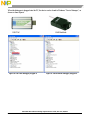
NXP MWCT1x0x is a wireless power transmitter reference design that allows you to evaluate the performance of the WCT1000 chip, which features a fully integrated digital demodulator and supports multiple types of Rx modulation signals. Some of the MWCT1x0x capabilities include:
- Integrated digital demodulation in the chip.
- Supports multiple types of Rx modulation signals.
- Supports FOD (Foreign Object Detection) and four types of Foreign Object protection.
- Supports Resonance Shift FOD (RS FOD).
- Supports the Qi 1.1 receiver with 5 V DC@1A output power capability.
- Super low standby power.


-
 1
1
-
 2
2
-
 3
3
-
 4
4
-
 5
5
-
 6
6
-
 7
7
-
 8
8
-
 9
9
-
 10
10
-
 11
11
-
 12
12
-
 13
13
-
 14
14
-
 15
15
-
 16
16
-
 17
17
-
 18
18
-
 19
19
-
 20
20
-
 21
21
-
 22
22
-
 23
23
-
 24
24
-
 25
25
-
 26
26
-
 27
27
-
 28
28
-
 29
29
-
 30
30
-
 31
31
-
 32
32
-
 33
33
-
 34
34
-
 35
35
-
 36
36


NXP MWCT1x0x is a wireless power transmitter reference design that allows you to evaluate the performance of the WCT1000 chip, which features a fully integrated digital demodulator and supports multiple types of Rx modulation signals. Some of the MWCT1x0x capabilities include:
- Integrated digital demodulation in the chip.
- Supports multiple types of Rx modulation signals.
- Supports FOD (Foreign Object Detection) and four types of Foreign Object protection.
- Supports Resonance Shift FOD (RS FOD).
- Supports the Qi 1.1 receiver with 5 V DC@1A output power capability.
- Super low standby power.
Ask a question and I''ll find the answer in the document
Finding information in a document is now easier with AI
Related papers
Other documents
-
Freescale Semiconductor HCS12 Quick Reference Manual
-
Aptiv FM29000 User manual
-
-
Acer Aspire S 24 Setup Manual
-
-
-
NXP Semiconductors KEA128LEDLIGHTRD Installation Instructions Manual
-
-
-
infobit iMeeting W330 User manual