Page is loading ...

16574022
Edition 2
June 2006
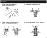
Air Grinder and Die Grinders
CD and CX Series, Horizontal
Parts Information
Save These Instructions

2 16574022_ed2
CD and CX Grinder and Die Grinder Exploded Diagram
(Dwg. TPA1267-7)
43
42
41
39
40
38
37
30
21
22
23
27
28
30
29
32
33
31
26
25
24
18
13
12
12
13
6A
6
8
9
11
10
5
7
4
4D
2
3
1
4A
4B
4C
45
46
47
14
15
16
17
19A
44
26A
19
20
36
35
34
BASIC CYCLONE POWER UNIT - ALL MODELS
ALL CD COLLET MODELS
ALL CX EXTENDED COLLET MODELS
ALL CD WHEEL MODELS
COLLET ASSEMBLY FOR
ALL
CD, CX MODELS
CD200
CD250
CX200
CX250
CD300
CD350
CX300

16574022_ed2 3
CD and CX Grinder and Die Grinder Parts List
Item Part Description Part
Number
Item Part Description Part Number
Common parts for ALL CD and CX
Grinders
18 Flow Ring
for CD200 and CX200
1 Inlet Assembly LG1-A465A (20000 rpm) (grey) LG1-103-0
2 Inlet Screen R1602-61 for CD250 and CX250
• 3 Inlet Seal 85H-167 (25000 rpm) (brown) LG1-103-1
Throttle Valve Kit LG1-K300 for CD300 and CX300
4 Throttle Valve Case LG1-300A (30000 rpm) (khaki) LG1-103-2
4A Throttle Valve Spring Seat LG1-592 for CD350 (32000 rpm) (red) LG1-103-3
4B Throttle Valve Spring 7L-51 19 High Profile Flange LG1-23
4C Throttle Valve AG210-302 # 19A Low Profile Concentric Flange
4D Throttle Valve Seat LG1-303 (for all models ending in C or MC) LG1R-23
5 Motor Housing LG1-40 20 Flange Clamp LG1-29
6 Throttle Lever LG1-273 Additional parts
6A Locking Throttle Lever Assembly for all CD collet models
(standard equipment on models 21 Clamp Spacer LG1-46
ending in C, L, MC or ML; optional for 22 Clamp Nut LG1-27
all others) LG1-A400 23 Collet Body LG1-290
* Lever Lock LG1-402 Additional parts for all collet models
* Lock Spring LG1-405 24 Collet
* Lock Pin 5UT-757 6 mm (-EU models) DG110-700-6mm
7 Throttle Lever Pin 61H-120 1/4” (standard domestic) DG110-700-G4
8 Throttle Valve Plunger LG1-191 1/8” (available at extra price) DG110-700-G2
9 Rear Rotor Bearing DG230-22 25 Nosepiece AG210-698A
• 10 Rear Rotor Bearing Spacer (2) DG20-278 26 Collet Nut AG210-699A
• 11 Rear Rotor Bearing Retainer LG1-118 26A Collet Wrench (11/16” x 7/16” )
12 Rotor (included with all models) (2) DG20-69A
for CD300, CX300 and Additional parts for all
CD350 (3 slots) LG1-53-3 extended CX collet models
for all others (5 slots) LG1-53-5 27 Arbor Coupling LE1-304
• 13 Vane Packet (set of 5 Vanes) LG1-42-5 28 Clamp Sleeve LE1-276
14 Front End Plate LG1-11 29 Rear Arbor Bearing AG210-24
15 Front End Plate Spacer DG10-65-5 30 Arbor Bearing Nut (2) LE1-85
• 16 Front Seal Cup LG1-32 31 Extension Arbor LE1-4A-3
17 Front Rotor Bearing LG1-24 32 Arbor Housing Assembly LE1-A20-3
33 Front Arbor Bearing AGS241-511
* Not illustrated.
• To keep downtime to a minimum, it is desirable to have on hand certain repair parts. We recommend that you stock one
(pair or set) of each part indicated by a bullet (•) for every four tools in service.
WARNING
# Always install a Locking Throttle Lever Assembly (6A) on a tool with a Low Profile Concentric Flange (19A). Do not
equip a tool with a standard non-locking Throttle Lever (6) and Low Profile Concentric Flange. This can allow the tool
to continue to run if dropped or set down.
† When ordering a Piped-Away Exhaust Kit, make certain the wrench hex on the Inlet Assembly of your tool is threaded. If it is
NOT threaded, order a new Inlet Assembly (Part No. LG1-A465A).
+ Standard equipment on models ending in M, MC or ML and ALL Front Exhaust models; optional equipment on all other
models.

4 16574022_ed2
Additional parts for all CD wheel * Nameplate
models for CD200 models ending in -EU LG120-EU-301
34 Clamp Spacer LG1-46H63 for all other CD200 models LG120-301
35 Clamp Nut LG1-28 for CD250 models ending in -EU LG125-EU-301
36 Guard Adapter Assembly LA1-A710 for all other CD250 models LG125-301
37 Guard Adapter Screw 804-634 for CD300 models ending in -EU LG130-EU-301
38 Wheel Guard AG20-106-3 for all other CD300 models LG130-301
39 Wheel Guard Mounting Screw (3) LA1-667 for CD350 models ending in -EU LG135-EU-301
40 Mounting Screw Washer (3) R2-320 for all other CD350 models LG135-301
41 Straight Wheel Adapter LG1-4-H63 for CX200 models ending in -EU LE120-EU-301
42 Wheel Flange DEG31-16 for all other CX200 models LE120-301
43 Flange Nut 23-697 for CX250 models ending in -EU LE125-EU-301
44 Clamp Nut Wrench (1-3/16” ) LA2-253 for all other CX250 models LE125-301
Accessories for all CD and CX for CX300 models ending in -EU LE130-EU-301
models for all other CX300 models LE130-301
† Piped-Away Exhaust Kit LG1-K284
+ 45 Exhaust Hose Adapter LG1-284
+ 46 Exhaust Hose Retainer LG1-67
+ 47 Exhaust Hose 3RL-284
* Variable Speed Control LG1-A1015
* Warning Label
for models ending in H63-EU EU-63-99
for all other models ending
in -EU EU-99
for all other models LG1-99
* Not illustrated.
† When ordering a Piped-Away Exhaust Kit, make certain the wrench hex on the Inlet Assembly of your tool is threaded. If it is
NOT threaded, order a new Inlet Assembly (Part No. LG1-A465A).
+ Standard equipment on models ending in M, MC or ML and ALL Front Exhaust models; optional equipment on all other
models.
Item Part Description Part
Number
Item Part Description Part Number

16574022_ed2 5
CD and CX Router Attachment Assembly Exploded Diagram
(Dwg.TPC612)
CD and CX Router Attachment Assembly Parts List
Parts and Maintenance
When the life of the tool has expired, it is recommended that the tool be disassembled, degreased and parts be separated by
material so that they can be recycled.
Tool repair and maintenance should only be carried out by an authorized Service Center.
Refer all communications to the nearest Ingersoll Rand Office or Distributor.
Related Documentation
For additional information refer to:
Product Safety Information Manual 04584959 and 04580288.
Product Information Manual 16576282 and 16576308.
Product Maintenance Information Manual 16575078.
Manuals can be downloaded from www.irtools.com.
67
63
65
61
64
66
68
62
26
25
24
23
60
Item Part Description Part Number
Router Attachment Assembly (for 1/4” diameter bits) CD-RK4
60 Motor Clamp Nut LG1R-27
61 Nosepiece Adapter LG1R-124
62 Adapter Lock Screw 0E9-561
63 Nosepiece Assembly LG2-A125-1
64 Nosepiece Bearing TD200-127
65 Bearing Retaining Ring RXA21-343
66 Locknut R120-126
67 Locknut Wrench LG2-237
68 Sprag Pin 244-302

6 16574022_ed2
Notes

16574022_ed2 7
Notes

www.irtools.com
© 2006 Ingersoll Rand Company
/