Page is loading ...

Refer All Communications to the Nearest
Ingersoll–Rand Office or Distributor.
Ingersoll–Rand Company 1999
Printed in U.S.A.
03537818
Form P6934
Edition 7
September, 1999
OPERATION AND MAINTENANCE
MANUAL FOR SERIES
TD, TX AND TXD GRINDERS
Series TD, TX and TXD Grinders are designed for close–quarter work in the metal fabricating
industry, shipyards, pipe fabrication, die manufacturing and limited space applications. They
are particularly good where conduits, pipes, ducts, etc. pass through bulkheads or frames.
These small Grinders are very efficient for grinding weld bead and leaving a fine finish.
Ingersoll–Rand is not responsible for customer modification of tools for applications on which
Ingersoll–Rand was not consulted.
IMPORTANT SAFETY INFORMATION ENCLOSED.
READ THIS MANUAL BEFORE OPERATING TOOL.
IT IS THE RESPONSIBILITY OF THE EMPLOYER TO PLACE THE INFORMATION
IN THIS MANUAL INTO THE HANDS OF THE OPERATOR.
FAILURE TO OBSERVE THE FOLLOWING WARNINGS COULD RESULT IN INJURY.
PLACING TOOL IN SERVICE
• Always operate, inspect and maintain this tool in
accordance with American National Standards
Institute Safety Code for Portable Air Tools
(ANSI B186.1).
• For safety, top performance, and maximum durability
of parts, operate this tool at 90 psig (6.2 bar/620 kPa)
maximum air pressure at the inlet with 3/8” (10 mm)
inside diameter air supply hose.
• Always turn off the air supply and disconnect the air
supply hose before installing, removing or adjusting
any accessory on this tool, or before performing any
maintenance on this tool.
• Do not use damaged, frayed or deteriorated air hoses
and fittings.
• Be sure all hoses and fittings are the correct size and
are tightly secured. See Dwg. TPD905–1 for a typical
piping arrangement.
• Always use clean, dry air at 90 psig maximum air
pressure. Dust, corrosive fumes and/or excessive
moisture can ruin the motor of an air tool.
• Do not lubricate tools with flammable or volatile
liquids such as kerosene, diesel or jet fuel.
• Do not remove any labels. Replace any damaged label.
USING THE TOOL
• Always wear eye protection when operating or
performing maintenance on this tool.
• Always wear hearing protection when operating this
tool.
• Keep hands, loose clothing and long hair away from
rotating end of tool.
• Anticipate and be alert for sudden changes in motion
during start up and operation of any power tool.
• Keep body stance balanced and firm. Do not
overreach when operating this tool. High reaction
torques can occur at or below the recommended air
pressure.
• Tool accessories may continue to rotate briefly after
throttle is released.
• Air powered tools can vibrate in use. Vibration,
repetitive motions or uncomfortable positions may be
harmful to your hands and arms. Stop using any tool
if discomfort, tingling feeling or pain occurs. Seek
medical advice before resuming use.
• Use accessories recommended by Ingersoll–Rand.
• This tool is not designed for working in explosive
atmospheres.
• This tool is not insulated against electric shock.
The use of other than genuine Ingersoll–Rand replacement parts may result in safety hazards, decreased tool performance, and
increased maintenance, and may invalidate all warranties.
Repairs should be made only by authorized trained personnel. Consult your nearest Ingersoll–Rand Authorized Servicenter.
F
E
P
TPD1430
REV.000

2
WARNING LABEL IDENTIFICATION
FAILURE TO OBSERVE THE FOLLOWING WARNINGS COULD RESULT IN INJURY.
Always wear eye protection
when operating or perform-
ing maintenance on this
tool.
WARNING
WARNING
Always wear hearing
protection when operating
this tool.
Always turn off the air sup-
ply and disconnect the air
supply hose before install-
ing, removing or adjusting
any accessory on this tool,
or before performing any
maintenance on this tool.
WARNING
Air powered tools can vibrate
in use. Vibration, repetitive
motions or uncomfortable po-
sitions may be harmful to your
hands and arms. Stop using
any tool if discomfort, tingling
feeling or pain occurs. Seek
medical advice before resum-
ing use.
WARNING
Do not carry the tool by
the hose.
WARNING
WARNING
Do not use damaged, frayed
or deteriorated air hoses
and fittings.
WARNING
Keep body stance balanced
and firm. Do not overreach
when operating this tool.
WARNING
Operate at 90 psig (6.2 bar/
620 kPa) Maximum air pressure.
90 psig
(6.2bar/620kPa)
GRINDER SPECIFIC WARNINGS
FAILURE TO OBSERVE THE FOLLOWING WARNINGS COULD RESULT IN INJURY.
• Do not use this tool if actual free speed exceeds the
nameplate rpm.
• Before mounting a wheel, after any tool repair or
whenever a Grinder is issued for use, check free
speed of Grinder with a tachometer to make certain
its actual speed at 90 psig (6.2 bar/620 kPa) does not
exceed rpm stamped or printed on the nameplate.
Grinders in use on the job must be similarly
checked at least once each shift.
• Always use the recommended Ingersoll–Rand
Wheel Guard furnished with the Grinder.
• Do not use any grinding wheel, bur or other
accessory having a maximum operating speed less
than the free speed of the Grinder in which it is
being used. Always conform to maximum rpm on
grinding wheel blotters.
• Inspect all grinding wheels for chips or cracks prior to
mounting. Do not use a wheel that is chipped or
cracked or otherwise damaged. Do not use a wheel
that has been soaked in water or any other liquid.
• Make certain grinding wheel properly fits the
arbor. Do not use reducing bushings to adapt a
wheel to any arbor unless such bushings are
supplied by and recommended by the wheel
manufacturer.
• After mounting a new wheel, hold the Grinder
under a steel workbench or inside a casting and run it
for at least 60 seconds. Make certain no one is
within the operating plane of the grinding wheel. If
a wheel is defective, improperly mounted or the
wrong size and speed, this is the time it will usually
fail.
• When starting with a cold wheel, apply it to the
work slowly until the wheel gradually warms up.
Make smooth contact with the work and avoid
any bumping action or excessive pressure.
• Always replace a damaged, bent or severely worn
wheel guard. Do not use a wheel guard that has
been subjected to a wheel failure.
• Make certain wheel flanges are at least 1/3 the
diameter of grinding wheel, free of nicks, burrs and
sharp edges. Always use wheel flanges furnished by
the manufacturer; never use a makeshift flange or a
plain washer. Tighten Flange Nut securely.
• Guard opening must face away from operator.
Bottom of wheel must not project beyond guard.
• Series TD120 Grinders have a free speed of 12,000
rpm; Series TD180, TX180 and TXD180 Grinders
have a free speed of 18,000 rpm; Series TD200 and
TX200 Grinders have a free speed of 25,000 rpm,
when operated at 90 psig (6.2 bar/620 kPa) air
pressure. Operation at higher air pressure will result
in excessive speed.
• Always match collet size with accessory shank size.
• Always insert tool shank no less than 10 mm in the
collet. Tighten Collet Nut securely to prevent
accessory from working out during operation of the
Grinder. Check tightness of Collet Nut before
operating the Grinder. Pay particular attention to
the fact that allowed speed of a mounted point is
lowered when the length of the shaft is increased
between end of collet and mounted point (overhang).
REV.000

3
GRINDER SPECIFIC WARNINGS
WARNING: Incorrect combinations of grinding wheel, wheel guard and tool speed could result in injury.
Correct combinations are specified below:
Guard Part Number Wheel Type Wheel Diameter
in. (mm)
Maximum Wheel
Thickness
in. (mm)
Maximum Speed
rpm
LE2–931 1 3 (76) 1/2 (12.7) 20 500
PLACING TOOL IN SERVICE
LUBRICATION
Ingersoll–Rand No. 10 Ingersoll–Rand No. 68
Ingersoll–Rand No. 50
Always use an air line lubricator with these tools.
We recommend the following Filter–Lubricator–Regulator
Unit:
For USA – No. C28–04–FKG0–28
After each two hours of operation, if an air line lubricator is
not used, inject 1/2 to 1 cc of Ingersoll–Rand No. 10 Oil into
the Air Inlet.
Do not mark any nonmetallic surface of this tool with
customer identification codes. Such action could affect tool
performance.
MAIN LINES 3 TIMES
AIR TOOL INLET SIZE
TO
AIR
SYSTEM
TO
AIR
TOOL
LUBRICATOR
REGULATOR
FILTER
BRANCH LINE 2 TIMES
AIR TOOL INLET SIZE
DRAIN REGULARLY
COMPRESSOR
(Dwg. TPD905–1)
MOUNTING THE ROUTER
ATTACHMENT
To mount a TD–RK4 or TD–RK6 Router Attachment to a
TD200 or TD250 Grinder having a collet, proceed as follows:
1. Use the Collet Body Wrench to hold the Collet Body
from turning and using the Collet Nut Wrench , unscrew
and remove the Collet Nut Assembly from the Grinder.
Remove the Collet .
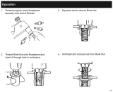
2. Grasp the tool in copper–covered or leather–covered vise
jaws with the spindle upward and using a 1–1/2” wrench,
unscrew and remove the Clamp Nut . This is a left–hand
thread, rotate the Nut clockwise to remove it.
3. Remove the Clamp Spacer and install the Router
Attachment Clamp Spacer .
4. Thread the Clamp Nut onto the Housing and tighten the
Nut between 20 and 25 ft–lb (27 and 34 Nm) torque. This
is a left–hand thread, rotate the Nut counterclockwise
to tighten it.
5. Insert the Collet into the Collet Body and loosely thread
the Collet Nut onto the Collet Body. Insert a router bit
into the Collet and tighten the Collet Nut.
6. Install the Nosepiece Adapter over the bit and collet
assembly and thread it onto the Clamp Spacer. Tighten
the Adapter between 2 and 3 ft–lb (2.7 and 4.0 Nm)
torque. This is a left–hand thread, rotate the Adapter
counterclockwise to tighten it.
7. Install the Adapter Lock Screw in the Adapter and
tighten it between 12 and 18 in–lb (1.3 and 2.0 Nm)
torque.
8. Thread the Lock Nut onto the Nosepiece Adapter.
9. Thread the Nosepiece Assembly onto the Adapter and
then back the Lock Nut against the Assembly. Tighten the
Lock Nut between 14 and 19 ft–lb (19.0 and 25.8 Nm)
torque.
10. If a Trimmer Guide is used, thread the Guide into the
Nosepiece Assembly and tighten the Guide between 3
and 4 ft–lb (4.1 and 5.4 Nm) torque.
REV.000

4
PLACING TOOL IN SERVICE
TRIMMER GUIDE
Trimmer Guide Dimensions
OFFSET
(Dwg. TPD1208)
PART NUMBER FOR ORDERING A B C D E
R120–128–2 (for 1/4” shank) 1–1/2 3/8 3/8 1/8 1/2–20NF
R120–128–7 (for 1/4” shank) 2–1/2 1/2 1/2 3/16 1/2–20NF
LG2–129–1 (for 3/8” shank) 2–1/2 1/2 5/8 1/8 5/8–18UNF
K Note: Offset = 1/2 (“B” dimension minus trimmer bit diameter.)
The following equipment is available at an extra price and must be ordered separately:
1. Router Attachment Assembly
for models using 1/4” diameter bits Part No. TD–RK4. . . . . . . . . . . . . . . . . . . . . . . . . . . . . . . . . . . . . . . . . . .
for models using 3/8” diameter bits Part No. TD–RK6. . . . . . . . . . . . . . . . . . . . . . . . . . . . . . . . . . . . . . . . . . .
2. Trimmer Guide (for Router Attachments)
for 1/4” shank Part No. R120–128–2. . . . . . . . . . . . . . . . . . . . . . . . . . . . . . . . . . . . . . . . . . . . . . . . . . . . . . . . . . . .
for 1/4” shank Part No. R120–128–7. . . . . . . . . . . . . . . . . . . . . . . . . . . . . . . . . . . . . . . . . . . . . . . . . . . . . . . . . . . .
for 3/8” shank Part No. LG2–129–1. . . . . . . . . . . . . . . . . . . . . . . . . . . . . . . . . . . . . . . . . . . . . . . . . . . . . . . . . . . .
All the models listed on Page 5 can be changed to front exhaust tools by reversing the Flow Ring and aligning the the indicator
marks with the letter “F” on the Housing. To order a front exhaust tool from the factory, substitute the letter “F” for the letter
“R” in the above models. Example: TD12RG4 Rear Exhaust Model becomes TD120FG4 Front Exhaust Model.
REV.000

5
PLACING TOOL IN SERVICE
NEW GRINDER TO ACCESSORY COLOR MATCHING GUIDE
Ingersoll–Rand has pioneered a new color code system
designed to:
1. Simplify the identification of rated tool speed via a
unique corresponding color match.
2. Easily communicate the appropriate backing pads and
accessories for each tool through a matching color
code system on the backing pads and/or other
corresponding Grinder accessories.
3. The chart below demonstrates the color code system
between the Grinder and the accessory.
(READ FROM LEFT TO RIGHT)
(Dwg. TPD1146–1)
SPÉCIFICATIONS
1/4” COLLET
Model Speed/rpm
TD250RG4 25,000
TD200RG4 20,000
TD180RG4 18,000
TD120RG4 12,000
1/4” COLLET
TX250RG4 25,000
TX180RG4 18,000
TX120RG4 12,000
3” WHEEL GUARD
TX180RH63 18,000
3” WHEEL GUARD
TXD180RH63 18,000
REV.000

MAINTENANCE SECTION
22
PART NUMBER FOR ORDERING PART NUMBER FOR ORDERING
Common parts for ALL TD, TX and TXD Grinders
15 Front End Plate Spacer . . . . . . . . . . . . . . . . . . . . . LG2–65
1 Inlet Assembly . . . . . . . . . . . . . . . . . . . . . . . . . . . . . . . . . LG2–A465 • 16 Front Seal Cup Assembly . . . . . . . . . . . . . . . . . . . 61H–A32
2 Inlet Screen . . . . . . . . . . . . . . . . . . . . . . . . . . . . . . . R1602–61 17 Front Rotor Bearing . . . . . . . . . . . . . . . . . . . . . . . . LG2–24
• 3 Inlet Seal . . . . . . . . . . . . . . . . . . . . . . . . . . . . . . . . . R18LF–21 18 Flow Ring
4 Throttle Valve Spring Seat . . . . . . . . . . . . . . . . . . . . . . . . LG3–592 for TD120 and TX120 (12 000 rpm)
4A Throttle Valve Spring . . . . . . . . . . . . . . . . . . . . . . . . . . . . 7L–51 (grey) . . . . . . . . . . . . . . . . . . . . . . . . . . . . . . LG2–103–0
4B Throttle Valve . . . . . . . . . . . . . . . . . . . . . . . . . . . . . . . . . LG2–302 for TD180, TX180 and TXD180
4C Throttle Valve Seat . . . . . . . . . . . . . . . . . . . . . . . . . . . . . LG2–303 (18 000 rpm) (brown) . . . . . . . . . . . . . . . . . LG2–103–1
4D Throttle Valve Case . . . . . . . . . . . . . . . . . . . . . . . . . . . . . LG2–300A for TD200 and TX200 (20 000 rpm)
5 Motor Housing . . . . . . . . . . . . . . . . . . . . . . . . . . . . . . . . . LG2–40 (khaki) . . . . . . . . . . . . . . LG2–103–2
6 Throttle Lever . . . . . . . . . . . . . . . . . . . . . . . . . . . . . . . . . LG2–273 for TD250 and TX250(25 000 rpm)
6A Locking Throttle Lever Assembly (red) . . . . . . . . . . . . . . . . . . . . . . . . . . . . . . . LG2–103–3
(for all models ending in L or C) . . . . . . . . . . . . . . . . . . . LG2–A400 19 High Profile Flange . . . . . . . . . . . . . . . . . . . . . . . . LG2–23
* Lever Lock . . . . . . . . . . . . . . . . . . . . . . . . . . . . . . . . LG1–402 # 19A Low Profile Concentric Flange (for all models
* Lock Spring . . . . . . . . . . . . . . . . . . . . . . . . . . . . . . . LG1–405 ending in C) . . . . . . . . . . . . . . . . . . . . . . . . . . . . . . LG3R–23
* Lock Pin . . . . . . . . . . . . . . . . . . . . . . . . . . . . . . . . . . 5UT–757 20 Flange Clamp . . . . . . . . . . . . . . . . . . . . . . . . . . . . . LG2–29
7 Throttle Lever Pin . . . . . . . . . . . . . . . . . . . . . . . . . . . . . . 61H–120 + 20A Exhaust Hose Adapter . . . . . . . . . . . . . . . . . . . . . . LG2–184
8 Throttle Valve Plunger . . . . . . . . . . . . . . . . . . . . . . . . . . . LG2–191 + 20B Exhaust Hose . . . . . . . . . . . . . . . . . . . . . . . . . . . . . 3RL–284
9 Rear Rotor Bearing . . . . . . . . . . . . . . . . . . . . . . . . . . . . . R120–127 + 20C Hose Retainer . . . . . . . . . . . . . . . . . . . . . . . . . . . . . 6WT–203
• 10 Rear Rotor Bearing Spacer (2) . . . . . . . . . . . . . . . . . . . . 400–25–191 * Warning Label
• 11 Rear Rotor Bearing Retainer . . . . . . . . . . . . . . . . . . . . . . LG1–118 for models ending in H63–EU . . . . . . . . . . . EU–63–99
12 Rotor . . . . . . . . . . . . . . . . . . . . . . . . . . . . . . . . . . . . . . . . LG2–53–4 for all other models ending in –EU . . . . . . . EU–99
• 13 Vane Packet (set of 4 Vanes) . . . . . . . . . . . . . . . . . . . . . . DG21–42–4 for all other models . . . . . . . . . . . . . . . . . . . LG2–99
14 Front End Plate . . . . . . . . . . . . . . . . . . . . . . . . . . . . . . . . LG2–11
* Not illustrated.
• To keep downtime to a minimum, it is desirable to have on hand certain repair parts. We recommend that you stock one (pair or set) of each part indicated by a
bullet (•) for every four tools in service.
+ Standard equipment with models ending in M, MC or ML and ALL Front Exhaust models; optional equipment on all other models.
# Always install a Locking Throttle Lever Assembly (6A) on a tool with a Low Profile Concentric Flange (19A). Do not equip a tool with a standard
non–locking Lever (6) and Low Profile Concentric Flange. This can allow the tool to continue to run if dropped or set down.
REV.000

MAINTENANCE SECTION
23
PART NUMBER FOR ORDERING PART NUMBER FOR ORDERING
* Nameplate 34 Arbor . . . . . . . . . . . . . . . . . . . . . . . . . . . . . . . . LE2–4–5
for TD120 models ending in –EU . . . . LG212–EU–301 35 Arbor Housing . . . . . . . . . . . . . . . . . . . . . . . . . LE2–20–5
for all other TD120 models . . . . . . . . . LG212–301 36 Arbor Housing Plug . . . . . . . . . . . . . . . . . . . . . EG220–92
for TD180 models ending in –EU . . . . LG218–EU–301 37 Front Arbor Bearing . . . . . . . . . . . . . . . . . . . . WFS182–22
for all other TD180 models . . . . . . . . . LG218–301 37A Arbor Bearing Shield (for models
for TD200 models ending in –EU . . . . LG220–EU–301 ending in G4) . . . . . . . . . . . . . . . . . . . . . . . . . . LE2–200
for all other TD200 models . . . . . . . . . LG220–301 38 Arbor Bearing Retaining Ring . . . . . . . . . . . . . W22–118
for TD250 models ending in –EU . . . . LG225–EU–301
Parts common to all
for all other TD250 models . . . . . . . . . LG225–301
models ending in G4
for TX120 models . . . . . . . . . . . . . . . . . LE212–301 39 Collet Body . . . . . . . . . . . . . . . . . . . . . . . . . . . LG2–290
for TX180 models ending in –EU . . . . LE218–EU–301 39A Front Seal Cup . . . . . . . . . . . . . . . . . . . . . . . . . 61H–32
for all other TX180 models . . . . . . . . . LE218–301 40 Collet
for TXD180 models ending in –EU . . . LED218–EU–301 for models ending in RT4 or –EU . . . . G160HD–700–6mm
for all other TXD180 models . . . . . . . . LED218–301 for all other models . . . . . . . . . . . . . . . . G160HD–700–1/4
for TX200 models . . . . . . . . . . . . . . . . . LE220–301 41 Collet Nut Assembly . . . . . . . . . . . . . . . . . . . . DG120–699A
for TX250 models ending in –EU . . . . LE225–EU–301 41A Collet Body Wrench . . . . . . . . . . . . . . . . . . . . DG10–69
for all other TX250 models . . . . . . . . . LE225–301 41B Collet Nut Wrench . . . . . . . . . . . . . . . . . . . . . . DG120–69
Additional parts for all TD models Parts common to all
21 Clamp Spacer . . . . . . . . . . . . . . . . . . . . . . . . . . LG2–46
models ending in H63
22 Clamp Nut . . . . . . . . . . . . . . . . . . . . . . . . . . . . LG2–27 42 Guard Adapter Assembly . . . . . . . . . . . . . . . . LE2–A710
Additional parts for all
43 Guard Adapter Screw . . . . . . . . . . . . . . . . . 231–638
extended TXD models
44 3” Wheel Guard . . . . . . . . . . . . . . . . . . . . . . . . LE2–931
23 Clamp Sleeve . . . . . . . . . . . . . . . . . . . . . . . . . . LE2–176 45 Wheel Guard Mounting Screw (3) . . . . . . . . . LE2–667
24 Arbor . . . . . . . . . . . . . . . . . . . . . . . . . . . . . . . . LE2–4 46 Mounting Screw Washer (3) . . . . . . . . . . . . . . L01–67
25 Arbor Housing . . . . . . . . . . . . . . . . . . . . . . . . . LE2–20 47 3” Straight Wheel Adapter . . . . . . . . . . . . . . . LE2–4–H63
26 Arbor Housing Plug . . . . . . . . . . . . . . . . . . . . . EG220–92 47A Front Seal Cup . . . . . . . . . . . . . . . . . . . . . . . . . 61H–32
27 Front Arbor Bearing . . . . . . . . . . . . . . . . . . . . WFS182–22 48 3” Wheel Flange . . . . . . . . . . . . . . . . . . . . . . . DEG31–16
28 Arbor Bearing Retaining Ring . . . . . . . . . . . . . W22–118 49 Flange Nut . . . . . . . . . . . . . . . . . . . . . . . . . . . . 23–697
Additional parts for all TX models Accessories
29 Arbor Coupling . . . . . . . . . . . . . . . . . . . . . . . . LE2–304 * Bearing Inserting Tool (for TX and TXD
30 Clamp Sleeve . . . . . . . . . . . . . . . . . . . . . . . . . . LE2–276 models) (2 pieces) . . . . . . . . . . . . . . . . . . . . . . LE2–950
31 Arbor Bearing Nut (2) . . . . . . . . . . . . . . . . . . . LE2–85 * Cone Wheel Adapter (for TX models) . . . . . . LE2–104–L6
32 Coupling Retaining Ring (2) . . . . . . . . . . . . . . RX3–729 * Exhaust Deflector Assembly . . . . . . . . . . . . . . 04353207
33 Rear Arbor Bearing . . . . . . . . . . . . . . . . . . . . . LE2–22
* Not illustrated.
REV.000

24
MAINTENANCE SECTION
ROUTER ATTACHMENT FOR MODELS TD200 AND TD250 WITH COLLETS
(Dwg. TPC542)
PART NUMBER FOR ORDERING
Router Attachment Assembly
for models using 1/4” diameter bits . . . . . . . . . . . . . . . . . . . . . . . . . . . . . . . TD–RK4
for models using 3/8” diameter bits . . . . . . . . . . . . . . . . . . . . . . . . . . . . . . . TD–RK6
75 Clamp Spacer . . . . . . . . . . . . . . . . . . . . . . . . . . . . . . . . . . . . . . . . . . . . . . . . . . . . . . . . . . LG2–19
76 Nosepiece Adapter . . . . . . . . . . . . . . . . . . . . . . . . . . . . . . . . . . . . . . . . . . . . . . . . . . . . . . LG2–124
77 Adapter Lock Screw . . . . . . . . . . . . . . . . . . . . . . . . . . . . . . . . . . . . . . . . . . . . . . . . . . . . 0E9–561
78 Nosepiece Assembly
for models using 1/4” collet . . . . . . . . . . . . . . . . . . . . . . . . . . . . . . . . . . . . . LG2–A125–1
for models using 3/8” collet . . . . . . . . . . . . . . . . . . . . . . . . . . . . . . . . . . . . . LG2–A125–3
79 Nosepiece Bearing
for LG2–A125–1 . . . . . . . . . . . . . . . . . . . . . . . . . . . . . . . . . . . . . . . . . . . . . . TD200–127
for LG2–A125–3 . . . . . . . . . . . . . . . . . . . . . . . . . . . . . . . . . . . . . . . . . . . . . . G160–22
80 Bearing Retaining Ring
for LG2–A125–1 . . . . . . . . . . . . . . . . . . . . . . . . . . . . . . . . . . . . . . . . . . . . . . RXA21–343
for LG2–A125–3 . . . . . . . . . . . . . . . . . . . . . . . . . . . . . . . . . . . . . . . . . . . . . . 3RL–28
81 Lock Nut . . . . . . . . . . . . . . . . . . . . . . . . . . . . . . . . . . . . . . . . . . . . . . . . . . . . . . . . . . . . . R120–126
82 Lock Nut Wrench . . . . . . . . . . . . . . . . . . . . . . . . . . . . . . . . . . . . . . . . . . . . . . . . . . . . . . . LG2–237
REV.000

25
MAINTENANCE SECTION
Always wear eye protection when operating or
performing maintenance on this tool.
Always turn off the air supply and disconnect the air
supply hose before installing, removing or adjusting
any accessory on this tool, or before performing any
maintenance on this tool.
LUBRICATION
Whenever one of these Grinders is disassembled for
overhaul or replacement of parts, lubricate as follows:
1. Always wipe the Vanes (13) with a light film of oil
before inserting them into the vane slots.
2. Lubricate the Front Seal Cup Assembly (16, 39A or
47A) with Ingersoll–Rand No. 50 Oil.
3. Inject 0.5 to 1.0 cc of Ingersoll–Rand No. 10 Oil into
the Air Inlet Assembly (1) after assembly.
DISASSEMBLY
General Instructions
1. Do not disassemble the tool any further than
necessary to replace or repair damaged parts.
2. When grasping a tool or part in a vise, always use
leather–covered or copper–covered vise jaws to
protect the surface of the part or tool and help prevent
distortion. This is particularly true of threaded
members and housings.
3. Do not remove any part which is a press fit in or on a
subassembly unless the removal of that part is
necessary for repairs or replacement.
4. Do not disassemble the tool unless you have a
complete set of new gaskets and O–rings for
replacement.
5. Do not press any needle bearing from a part unless
you have a new needle bearing on hand for
installation. Needle bearings are always damaged
during the removal process.
Steps common to ALL models ending in G4
1. Using the Collet Body Wrench (41A) to hold the
Collet Body (39) from turning and the Collet Nut
Wrench (41B) on the Collet Nut Assembly (41),
unscrew and remove the Nut.
2. Remove the Collet (40).
Steps common to ALL models ending in H63
1. Use an adjustable spanner wrench in one of the holes
in the Wheel Adapter (47) and a 9/16” wrench to
loosen and remove the Flange Nut (49). Remove the
Wheel Flange (48) and grinding wheel.
2. Using a 5/32” hex wrench, loosen the Guard
Adapter Screw (43) and pull the Guard Adapter
Assembly (42) and assembled Guard (44) from the
Arbor Housing (35).
Steps common to ALL TD models
1. Grasp the tool in copper–covered or leather–covered
vise jaws with the spindle upward and using a 1–1/2”
wrench, unscrew and remove the Clamp Nut (22).
This is a left–hand thread and must be rotated
clockwise.
2. Remove the Clamp Spacer (21) and Flange
Clamp (20).
3. Pull the Flange (19) and Flow Ring (18) off the front
of the Motor Housing (5).
4. Grasp the Collet Body and pull the assembled motor
out of the Motor Housing. Remove the Motor
Housing from the vise and remove the two Rear Rotor
Bearing Spacers (10) from the bottom of the Housing.
5. Remove the Vanes (13) from the Rotor (12).
6. Grasp the Rotor in copper–covered or leather–covered
vise jaws with the Collet Body (39) upward. Using the
Collet Body Wrench (41A), unscrew and remove the
Collet Body. Remove the Front Seal Cup Assembly
(39A) from the Collet Body.
Steps common to ALL TXD models
1. Use a screwdriver to remove the Arbor Housing Plug
(26) and rotate the Arbor (24) until the crosshole in
the Arbor is aligned with the opening in the Arbor
Housing (25).
2. Insert a 5/32” (4 mm) diameter hardened steel rod
approximately 6” (150 mm) long through the arbor
crosshole to sprag the Arbor. Using a spanner wrench
on the Wheel Adapter (47), unscrew and remove the
Adapter.
3. Grasp the tool in copper–covered or leather–covered
vise jaws with the spindle upward and using a 1–1/2”
wrench, unscrew and remove the Arbor Housing. This
is a left–hand thread and must be rotated clockwise.
4. Remove the Clamp Sleeve (23), Flange Clamp (20),
Flange (19) and Flow Ring (18) from the front of the
Motor Housing (5).
5. Using snap ring pliers, remove the Arbor Bearing
Retaining Ring (28).
6. Stand the Arbor Housing (25), threaded end upward,
on the table of an arbor press and using a rod or piece
of tubing that contacts the outer ring of the bearing,
press the Front Arbor Bearing (27) from the Arbor
Housing.
7. Grasp the Arbor and pull the assembled motor out of
the Motor Housing. Remove the Motor Housing from
the vise and remove the two Rear Rotor Bearing
Spacers (10) from the bottom of the Housing.
REV.000

26
MAINTENANCE SECTION
8. Remove the Vanes (13) from the Rotor (12).
9. Grasp the Rotor in copper–covered vise jaws with the
Arbor upward. Using a 5/32” diameter rod through
the crosshole, unscrew and remove the Arbor.
Steps common to ALL TX models
1. Use a screwdriver to remove the Arbor Housing Plug
(36) and rotate the Arbor (34) until the crosshole in
the Arbor is aligned with the opening in the Arbor
Housing (35).
2. Insert a 5/32” (4 mm) diameter hardened steel rod
approximately 6” (150 mm) long through the arbor
crosshole to sprag the Arbor.
For models ending in H63
Using a spanner wrench on the Wheel Adapter (47),
unscrew and remove the Adapter. Remove the Front
Seal Cup Assembly (47A) from the Adapter.
For models ending in G4
Using the Collet Body Wrench (41A) on the Collet
Body (39), unscrew and remove the Collet Body.
Remove the Front Seal Cup Assembly (39A) from the
Collet Body.
3. Grasp the tool in copper–covered or leather–covered
vise jaws with the spindle upward and using a 1–1/2”
wrench, unscrew and remove the Arbor Housing (35).
This is a left–hand thread and must be rotated
clockwise.
4. Remove the Clamp Sleeve (30), Arbor Coupling (29)
and the Flange Clamp (20).
5. Grasping the Arbor Bearing Nut (31), pull the Arbor
out of the Arbor Housing.
6. Using snap ring pliers, remove the Arbor Bearing
Retaining Ring (38) from the Arbor Housing.
7. For models ending in G4, remove the Arbor Bearing
Shield (37A).
8. Stand the Arbor Housing (35), threaded end upward,
on the table of an arbor press and using a rod or piece
of tubing that contacts the outer ring of the bearing,
press the Front Arbor Bearing (37) from the Arbor
Housing.
9. Insert a 5/32” (4 mm) diameter hardened steel rod
approximately 6” (150 mm) long through the
crosshole in the Arbor and using a 1/2” wrench on the
Arbor Bearing Nut, unscrew and remove the Nut.
10. Using an arbor press, press the Rear Arbor Bearing
(33) off the Arbor.
11. Pull the Flange (19) and Flow Ring (18) off the front
of the Motor Housing (5).
12. Grasp the Arbor Bearing Nut on the rotor shaft and
pull the assembled motor out of the Motor Housing.
Remove the Motor Housing from the vise and remove
the two Rear Rotor Bearing Spacers (10) from the
bottom of the Housing.
13. Remove the Vanes (13) from the Rotor (12).
14. Grasp the Rotor in copper–covered or leather–covered
vise jaws with the Arbor Bearing Nut upward. Using a
1/2” wrench, unscrew and remove the Arbor Bearing
Nut.
Steps common to ALL models
1. If the Front Rotor Bearing (17) must be replaced,
support the Front End Plate (14) between two blocks
on the table of an arbor press. Place the blocks as
close to the body of the Rotor (12) as possible and
press theRotor from the Bearing and End Plate.
Remove the Front End Plate Spacer (15) and Front
Seal Cup Assembly (16) from the hub of the Rotor.
2. If the Rear Rotor Bearing (9) must be replaced, use
snap ring pliers to remove the Rear Rotor Bearing
Retainer (11).
3. Using a bearing puller, pull the Rear Rotor Bearing
off the hub of the Rotor.
Disassembly of the Inlet and Throttle
1. Using a 6 point 15/16" socket, unscrew and remove
the Inlet Assembly (1).
2. Remove the Inlet Seal (3) and Inlet Screen (2) from
the Inlet.
3. Remove the Throttle Valve Spring Seat (4), Throttle
Valve Spring (4A) and Throttle Valve (4B)from the
Motor Housing (5).
4. If the Throttle Valve Seat (4C) must be replaced,
insert a hooked tool through the central opening of the
Seat and, catching the underside of the Seat, pull it
from the Housing.
5. If the Throttle Valve Cartridge Case (4D) must be
replaced, insert two hooked tools through the central
opening of the Case approximately 180 degrees apart
and, catching the underside of the Case, pull it from
the Housing.
6. Press the Throttle Lever Pin (7) from the Housing and
remove the Throttle Lever (6). Remove the Throttle
Valve Plunger (8).
ASSEMBLY
General Instructions
1. Always press on the inner ring of a ball–type bearing
when installing the bearing on a shaft.
2. Always press on the outer ring of a ball–type bearing
when pressing the bearing into a bearing recess.
3. Whenever grasping a tool or part in a vise, always use
leather–covered or copper–covered vise jaws. Take
extra care not to damage threads or distort housings.
4. Except for bearings, always clean every part and wipe
every part with a thin film of oil before installation.
5. Check every bearing for roughness. If an open bearing
must be cleaned, wash it thoroughly in clean solvent
and dry with a clean cloth. Sealed or shielded
bearings should not be cleaned. Work grease into
every open bearing before installation.
6. Apply a film of O–ring lubricant to every O–ring
before installation.
REV.000

27
MAINTENANCE SECTION
Assembly of the Inlet and Throttle
1. Insert the Throttle Valve Plunger (8) into the Motor
Housing (5).
2. Position the Throttle Lever (6) on the Motor Housing
and using an arbor press, press the Throttle Lever Pin
(7) into the Housing and Lever. The Lever will retain
the Plunger in the Housing.
3. If the Throttle Valve Cartridge Case (4D) was
removed, lubricate the outside and the throttle stem
end of the Case with O–ring lubricant. Using a
wooden dowel, push the Case, open end trailing, into
the Motor Housing.
4. If the Throttle Valve Seat (4C) was removed, use a
5/8” wooden dowel with a flat end to push the Seat
into the Motor Housing.
5. Push the small end of the Throttle Valve Spring (4A)
onto the end of the Throttle Valve (4B) with the short
stem until the Spring snaps into position around the
hub and remains there. Install the dish end of the
Throttle Valve Spring Seat (4) onto the large end of
the Throttle Valve Spring.
6. Holding the Housing with the Lever downward, make
sure the Plunger is out of the way and insert the
assembled Throttle Valve, long stem end leading, into
the housing recess.
7. Push the Inlet Screen (2), closed end leading, into the
Inlet Assembly (1). After moistening a new Inlet Seal
(3) with o–ring lubricant and being careful not to nick
the Seal on the threads of the Inlet, install the Seal on
the Inlet.
8. Thread the Inlet Assembly into the Housing and
tighten it between 13 to 15 ft–lb (18 to 20 Nm)
torque.
Assembly of the Motor
Steps common to ALL models
1. If the Rear Rotor Bearing (9) was removed, stand the
Rotor (12) upright on the table of an arbor press with
the threaded end downward. Make sure the threaded
end passes through a hole drilled in a block so that the
Rotor rests against the large rotor body. Press the Rear
Rotor Bearing onto the hub of the Rotor.
2. Install the Rear Rotor Bearing Retainer (11) in the
groove on the hub of the Rotor.
3. Install the Front End Plate (14), counterbored end
trailing, onto the threaded hub of the Rotor. Using
finger pressure, press the Front Seal Cup Assembly
(16), felt end trailing, onto the end of the Front End
Plate Spacer (15) that is opposite the large internal
bevel. Continue pressing until the felt end is flush
with the end of the Spacer. Lubricate the felt with
Ingersoll–Rand No. 50 Oil. Place the assembled
Spacer, Seal Assembly trailing, onto the threaded hub
of the Rotor. Make sure the Seal Assembly enters the
recess in the Front End Plate.
Before performing the next step, be aware that the
Front Rotor Bearing is a flush ground bearing and
must be installed in a specific manner. The end of
the Bearing with a black stain or hash marks must
be away from the Spacer.
4. Stand the Rotor on the table of an arbor press with the
threaded end upward and press the Front Rotor
Bearing (17) onto the hub of the Rotor.
5. Grasp the assembled Rotor in copper–covered or
leather–covered vise jaws with the threaded rotor hub
upward.
6. For TD models, using finger pressure, press the Front
Seal Cup Assembly (39A or 47A), felt end trailing,
onto the rotor end of the Collet Body (39)or Wheel
Adapter (47). Continue pressing until the felt end is
flush with the end of the Collet Body or Wheel
Adapter. Lubricate the felt with Ingersoll–Rand No.
50 Oil.
7. If the Front Arbor Bearing (27) must be replaced on a
Model TXD, proceed as follows before assembling
the motor:
a. Place the Clamp Sleeve (23) on the table of an
arbor press and install the large end of the Arbor
Housing (25) on the Clamp Sleeve.
b. Slide the Front Arbor Bearing onto the threaded
hub of the Arbor (24) and insert the Arbor, bearing
end trailing, into the Housing. Make certain the
end of the Arbor rests on the arbor press table and
the Bearing is aligned with the bore in the
Housing.
c. Install the small piece of the LE2–950 Bearing
Inserting Tool over the Arbor and press the
Bearing into the Housing until it stops against the
shoulder of the Arbor.
d. Remove the Arbor from the Housing and
Bearing but keep the parts together so that the
same parts are installed together. Do not mix and
match Arbors with Bearings and Housings.
8. Thread the Collet Body and Seal Assembly (for TD
models), Arbor (24) (for TXD models) or the Arbor
Bearing Nut (31), Retainer end leading, (for TX
models) onto the Rotor and using a torque wrench,
tighten the Collet Body, Arbor or Arbor Bearing Nut
between 14 and 19 ft–lb (19 and 26 Nm) torque.
9. Inject approximately 3/4 cc of Ingersoll–Rand No. 68
Grease into the small recess at the bottom of the
motor housing bore. Drop the two Rear Rotor
Bearing Spacers (10) into the bottom of the motor
housing bore.
10. Wipe each Vane (13) with a light film of oil and insert
a Vane into each vane slot in the Rotor.
REV.000

28
MAINTENANCE SECTION
11. Grasp the Collet Body, Arbor or Arbor Bearing
Nut and insert the assembled Rotor into the Motor
Housing (5).
12. Assemble the Flow Ring (18) with the Flange (19)
before installing the Flange on the Housing. Mate the
Flow Ring to the end of the Flange without
perforations. The positioning of the Flow Ring is
dictated by the desired exhaust. To set the tool
exhaust, proceed as follows:
a. For front exhaust tools, align the notched
projection on the edge of the Flow Ring with the
letter “F” on the Housing.
b. For rear exhaust tools, align the notched
projection on the edge of the Flow Ring with the
letter “R” on the Housing.
13. Install the assembled Flange, Flow Ring leading, onto
the front of the Motor Housing.
14. Grasp the Motor Housing in copper–covered or
leather–covered vise jaws with the Collet Body, Arbor
or Arbor Bearing Nut upward. Do not distort the
Housing.
15. Position the Flange Clamp (20) against the Flange.
Steps common to ALL TX models
1. Lubricate the Arbor Coupling (29) with
approximately 1 cc of Ingersoll–Rand No. 68 Grease
and position the Coupling over the Arbor Bearing Nut
(31). Position the Clamp Sleeve (30) over the Arbor
Coupling against the Front Rotor Bearing (17).
2. If the Rear Arbor Bearing (33) was removed, proceed
as follows:
a. Stand the larger piece of the LE2–950 Bearing
Inserting Tool on the table of an arbor press.
b. Place the Rear Arbor Bearing on the surface of the
Inserting Tool and align the central opening of the
Bearing with the central opening of the Inserting
Tool.
c. The large body of the Arbor (34) has an annular
groove between the crosshole and one threaded
end. Press that end of the Arbor into the Bearing
until the shoulder of the Arbor stops against the
Bearing.
3. If the Front Arbor Bearing (37) was removed from the
Arbor Housing (35), proceed as follows:
a. If the Rear Arbor Bearing was not removed from
the Arbor, insert a 5/32” (4 mm) hardened steel
rod approximately 6” (150 mm) long through the
crosshole and using a 1/2” wrench, unscrew and
remove the Arbor Bearing Nut (31) from the
Arbor. Do not remove the Bearing.
b. Stand the larger piece of the No. LE2–950 Bearing
Inserting Tool on the table of an arbor press and
insert the Arbor, Rear Arbor Bearing end leading,
into the central opening of the piece until the
Bearing stops against the top of the Inserting Tool.
c. Install the Arbor Housing, threaded end first, over
the Arbor until it stops against the Bearing and
pilots on the Bearing Inserting Tool.
d. Position the Front Arbor Bearing on the Arbor and
using the smaller piece of the No. LE2–950
Bearing Inserting Tool as a pressing tool and pilot,
press the Bearing onto the Arbor until it stops
against the arbor shoulder.
e. For models ending in G4, install the Arbor
Bearing Shield (37A) in the Housing against the
Bearing.
f. Using snap ring pliers, install the Arbor Bearing
Retaining Ring (38) in the Arbor Housing.
4. Insert a 5/32” (4 mm) hardened steel rod
approximately 6” (150 mm) long through the
crosshole and using a 1/2” wrench, thread the Arbor
Bearing Nut onto the Arbor against the Rear Arbor
Bearing. Tighten the Nut between 14 and 19 ft–lb (19
and 26 Nm) torque.
5. Align the rear Arbor Bearing Nut with the hex in the
Arbor Coupling. Thread the Arbor Housing onto the
Motor Housing and tighten the joint between 20 and
25 ft–lb (27 and 34 Nm) torque. This is a left–hand
thread. Turn counterclockwise to tighten.
6. For collet models, insert a 5/32” (4 mm) hardened
steel rod approximately 6” (150 mm) long through the
arbor crosshole. Thread the assembled Collet Body
onto the Arbor and using a torque wrench, tighten the
joint between 14 and 19 ft–lb (19 and 26 Nm) torque.
Steps common to ALL TXD models
1. Position the Clamp Sleeve (23) over the Arbor against
the Front Rotor Bearing (17).
2. Thread the Arbor Housing (25) onto the Motor
Housing and tighten the joint between 20 and 25 ft–lb
(27 and 34 Nm) torque. This is a left–hand thread.
Turn counterclockwise to tighten.
3. Using snap ring pliers, install the Arbor Bearing
Retaining Ring (28) in the Arbor Housing.
Steps common to ALL TD models
1. Position the Clamp Spacer (21) over the Arbor against
the Front Rotor Bearing (17).
2. Thread the Clamp Nut (22) onto the Housing and
tighten the Nut between 20 and 25 ft–lb (27 and
34 Nm) torque. This is a left–hand thread. Turn
counterclockwise to tighten.
REV.000

29
MAINTENANCE SECTION
Steps common to ALL models ending in H63
1. Insert a 5/32” (4 mm) diameter hardened steel rod
approximately 6” (150 mm) long through the opening
in the Arbor Housing and Arbor to keep the Arbor
from turning. Using an adjustable spanner wrench,
tighten the Wheel Adapter (47) between 14 and
19 ft–lb (19 and 26 Nm) torque.
2. Remove the rod and install the Arbor Housing Plug
(26or 36).
3. If the Wheel Guard (44) was removed from the Guard
Adapter (42), attach the Guard to the Adapter with the
three Wheel Guard Mounting Screws (45) and
Mounting Screw Lock Washers (46). Tighten each
Screw between 2–1/2 and 3 ft–lb (3.4 and 4.1 Nm)
torque.
4. Install the assembled Guard Adapter and Wheel
Guard on the front end of the Arbor Housing, flush
with the end of the Housing. Install the Guard
Adapter Screw (43) into the Adapter and tighten the
Screw between 3–1/2 and 4 ft–lb (4.7 and 5.4 Nm)
torque.
5. Install in order the wheel, Wheel Flange (48) and
Flange Nut (49).
6. Use an adjustable spanner wrench inserted into one of
the holes in the Wheel Adapter to hold the Adapter
from turning. Using a 9/16” wrench on the Flange
Nut, tighten the Nut securely.
Steps common to ALL models ending in G4
1. Insert the Collet (40) into the Collet Body (39).
2. Thread the Collet Nut Assembly (41) onto the Collet
Body and use the Collet Body Wrench (41A) and the
Collet Nut Wrench (41B) to tighten the Nut to the
Collet Body.
REV.000

30
MAINTENANCE SECTION
TROUBLESHOOTING GUIDE
Trouble Probable Cause Solution
Low power or low free speed Insufficient air pressure Check air line pressure at the Inlet of the Tool. It
must be 90 psig (6.2 bar/620 kPa).
Clogged muffler elements Disassemble the Tool and agitate bare Motor
Housing and Flange in clean, suitable, cleaning
solution. If elements cannot be cleaned, replace
the Motor Housing and/or the Flange.
Plugged Inlet Screen Clean the Inlet Screen in clean, suitable, cleaning
solution or replace the Screen.
Worn or broken Vanes Install a complete set of new Vanes.
Loose Clamp Nut or Arbor
Housing
Tighten the Nut or Housing to 20 to 25 ft–lb (27 to
34 Nm) torque.
Worn or broken Motor Housing Replace the Motor Housing.
Internal air leakage in the Motor
Housing indicated by high air
consumption/low speed or air
leaking out the front and rear
exhaust simultaneously.
Replace the Motor Housing.
Grit buildup under the Throttle
Lever restricting full Throttle
Valve Plunger movement.
Remove the Throttle Lever and clean the groove
in the Motor Housing.
Bent stem on Throttle Valve Replace the Throttle Valve.
Front Seal Cup Assembly
dragging against the shield of
the Front Rotor Bearing
Reposition the Front Seal Cup Assembly.
Excessive runout Bent rotor hub Replace the Rotor.
Loose Collet Nut Tighten the Collet Nut until snug.
Worn or damaged Collet or
Collet Nut
Replace the damaged component and retest.
Worn or damaged Front Rotor
Bearing
Replace the Front Rotor Bearing.
Bent, worn or broken Extension
Arbor on TX or TXD models
Replace the Extension Arbor if, when mounted
between centers, the runout on the arbor body
exceeds 0.002” T.I.R. or 0.0005” T.I.R. on the
bearing mounting diameters.
Worn or damaged Front Arbor
Bearing on TX or TXD models
Replace the Front Arbor Bearing.
Scoring of End Plate Worn Front End Plate Spacer or
Front End Plate
Install a new Front End Plate Spacer and Front
End Plate.
Worn Front Rotor Bearing Install a new Front Rotor Bearing.
REV.000

31
MAINTENANCE SECTION
TROUBLESHOOTING GUIDE
Trouble Probable Cause Solution
Leaky Throttle Valve Dirt accumulation on Throttle
Valve or Throttle Valve Seat
Disassemble, inspect and clean parts.
Worn Throttle Valve or Throttle
Valve Seat
Replace the Throttle Valve and/or Throttle Valve
Seat.
Excessive dirt build–up beneath
the Throttle Lever
Clean out the slot area.
Bent Throttle Valve Plunger Replace the Plunger.
Exhausts at wrong direction Incorrect orientation of the Flow
Ring
Reverse the face of the Flow Ring against the
Motor Housing.
Front Rotor Bearing runs hot Incorrect installation of the Front
Seal Cup Assembly
Reposition the Front Seal Cup Assembly flush
with the face of the Front End Plate Spacer.
Front End Plate Spacer rubbing
the bore of the Front End Plate
Replace the Front End Plate and Front End Plate
Spacer combination.
Incorrect Front Rotor Bearing
installation orientation
If a black stain or black hashmarks are not visible
on the face of the Bearing when it is assembled
with the End Plate and Rotor, the Bearing is
installed backwards. If possible, remove the Bear-
ing and install it correctly or replace the Bearing.
Slow tool idle Bent or leaky Throttle Valve Replace the Throttle Valve.
Air leakage around Flow Ring Damaged, mutilated or missing
Flange Clamp
Replace the Flange Clamp.
Damaged Flow Ring Replace the Flow Ring.
Rough operation/vibration Improper lubrication or dirt
buildup
Disassemble the Tool and clean in a suitable
cleaning solution. Assemble the Tool and inject
3 cc of the recommended oil into the Inlet and run
the Grinder long enough to coat the internal parts
with the oil.
Worn or broken Rear Rotor
Bearing or Front Rotor Bearing
Replace the worn or broken Bearings. Examine the
Front End Plate, Front End Plate Spacer Front Seal
Cup Assembly and Rear Rotor Bearing Spacers
and replace any damaged parts. If the rear end
plate is damaged, replace the Rotor.
Worn or broken Rear Arbor
Bearing in TX models or Front
Arbor Bearing in TX or TXD
models
Replace the worn or broken Bearing.
Dirt contaminated Front Arbor
Bearing in TX or TXD models
Replace the Bearing.
Bent, worn or broken Extension
Arbor on TX or TXD models
Replace the Extension Arbor if, when mounted
between centers, the runout on the arbor body ex-
ceeds 0.002” T.I.R. or 0.0005” T.I.R. on the bear-
ing mounting diameters.
SAVE THESE INSTRUCTIONS. DO NOT DESTROY.
REV.000
/