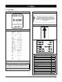
Airwell AQC 40-75 Installation and Maintenance Manual
- Category
- Heat pumps
- Type
- Installation and Maintenance Manual

English Deutsch EspañolItalianoFrançais
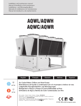
Air Cooled Water Chillers and Heat Pumps
Refroidisseurs de liquide à condensation par air et pompes à chaleur air-eau
Luftgekühlte Flüssigkeitskühler und Wärmepumpen
Refrigeratori d'Acqua e Pompe di Calore Raffreddati ad Aria
Enfriadores de Agua y Bomba de Calor Condensadas con Aire
Installation and maintenance manual
Manuel d'installation et de maintenance
Installations- und Wartungshandbuch
Manuale di installazione e di manutenzione
Manual de instalación y de mantenimiento
AQL/AQH 20-75
AQC 40-75
IOM AQ410-N.3GB
Part number / Code / Code / Codice / Código : 035B09040-000D
Supersedes / Annule et remplace / Annulliert und ersetzt / Annulla e sostituisce /
Anula y sustituye : 035B09040-000C
Notified Body / Organisme Notifié / Benannte Zertifizierungsstelle / Organismo
Notificato / Organismo Notificado N°. 1115
20
77 kW
20
86 kW
ISO 9001 certified management system

II

1
English
Table of Contents
1 - FOREWORD
1.1 Introduction ..........................................................................2
1.2 Warranty ..............................................................................2
1.3 Emergency stop / Normal stop .............................................2
1.4 An introduction to this manual ..............................................2
2 - SAFETY
2.1 Foreword ..............................................................................3
2.2 Definitions ............................................................................ 4
2.3 Access to the unit ...............................................................4
2.4 General precautions..............................................................4
2.5 Precautions against residual risks .........................................4
2.6 Precautions during maintenance operations ..........................5
2.7 Safety labels ................................................................. 6 & 7
2.8 Safety regulations ........................................................8 to 10
3 - TRANSPORT, HANDLING AND STORAGE
3.1 Inspection ..........................................................................11
3.2 Handling ............................................................................11
3.3 Anchoring ..........................................................................12
3.4 Storage ..............................................................................12
4 - INSTALLATION
4.1 Installation site ...................................................................13
4.2 External water circuit ................................................. 13 to 16
4.3 Water connections .............................................................17
4.4 Defrost water drainage (AQH only) .....................................17
4.5 Water buffer tank ...................................................... 17 & 18
4.6 Power supply .....................................................................18
4.7 Electrical connections................................................20 to 22
5 - START-UP
5.1 Preliminary checks ............................................................. 23
5.2 Start-up .............................................................................23
5.3 Checking the operation ....................................................... 23
5.4 Delivery to the customer .....................................................23
6 - AQL/AQH CONTROL
6.1 Electronic card control ........................................................24
6.2 Dip switches ......................................................................25
6.3 ALAr and LOg Menu ...........................................................28
6.4 SEnS Menu - Sensor reading .............................................. 29
6.5 SIF version configuration ....................................................29
7 - AQC CONTROL
7.1 Control of AQC with 2 compressors
The "CHILLER CONTROL" system .......................................30
7.2 Display ...............................................................................31
7.3 Keyboard ...........................................................................31
7.4 Alarms ............................................................................... 32
8 - PRODUCT DESCRIPTION
8.1 General information ............................................................ 33
8.2 Accessories AQL/AQH 20-35 ....................................34 to 36
8.3 Accessories AQL/AQH 40-75 .................................... 37 & 38
8.4 Refrigeration circuits .................................................39 to 43
9 - TECHNICAL DATA
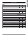
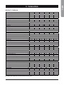
9.1 Hydraulic features .....................................................44 to 46
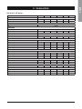
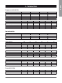
9.2 Physical data.............................................................47 to 57
9.3 Electrical data ............................................................ 58 & 59
9.4 Position of shock adsorbers
and weight distribution on supports .................................... 60
9.5 Dimensional Drawings ...............................................61 to 65
9.6 Space requirements ...........................................................66
10 - MAINTENANCE
10.1 General requirements .......................................................67
10.2 Planned maintenance ........................................................67
10.3 Refrigerant charge .............................................................68
10.4 Compressor ...................................................................... 68
10.5 Condenser .......................................................................68
10.6 Fans .................................................................................68
10.7 Dehydrating filter ............................................................... 68
10.8 Sight glass ........................................................................69
10.9 Thermostatic expansion valve............................................69
10.10 Evaporator ........................................................................69
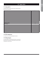
11 - TROUBLESHOOTING .......................................... 70
12 - SPARE PARTS
12.1 Spare part list.....................................................................71
12.2 Oil for compressors ............................................................71
12.3 Wiring diagrams ................................................................. 71
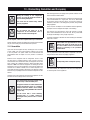
13 - DISMANTLING, DEMOLITION AND SCRAPPING
13.1 Generalities ........................................................................72

2
1 - Foreword
1.1 Introduction
Units, manufactured to state-of-the-art design and implementation
standards, ensure top performance, reliability and fitness to any type
of air-conditioning systems.
These units are designed for cooling water or glycoled water (and for
water heating in heat pump models) and are unfit for any purposes
other than those specified in this manual.
This manual includes all the information required for a proper
installation of the units, as well as the relevant operating and
maintenance instructions.
It is therefore recommended to read this manual carefully before
installation or any operation on the machine. The chiller installation
and maintenance must be carried out by skilled personnel only
(where possible, by one of Authorised Service Centers).
The manufacturer may not be held liable for any damage to people or
property caused by improper installation, start-up and/or improper
use of the unit and/or failure to implement the procedures and
instructions included in this manual.
1.2 Warranty
These units are delivered complete, tested and ready for being
operated. Any form of warranty will become null and void in the event
that the appliance is modified without manufacturer’s preliminary
written authorisation.
This warranty shall apply providing that the installation instructions
have been complied with (either issued by manufacturer, or deriving
from the current practice), and the Form 1 (“Start-up”) has been
filled-in and mailed to manufacturer (attn. After-Sales Service).
In order for this warranty to be valid, the following conditions shall
be met :
n The machine must be operated only by skilled personnel from
Authorised After-Sales Service.
n Maintenance must be performed only by skilled personnel - from
one of Authorised After-Sales Centers.
n Use only original spare parts.
n Carry out all the planned maintenance provided for by this manual
in a timely and proper way.
Failure to comply with any of these conditions will automatically void
the warranty.
1.3 Emergency stop / Normal stop
The emergency stop of the unit can be enabled using the master
switch on the control panel (move down the lever).
For a normal stop, press the relevant push-buttons.
To restart the appliance, follow the procedure detailed in this manual.
1.4 An introduction to the manual
For safety reasons, it is imperative to follow the instructions given
in this manual. In case of any damage caused by non-compliance
with these instructions, the warranty will immediately become null
and void.
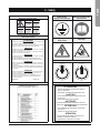
Conventions used throughout the manual :
DANGER
The DANGER sign recalls your attention to
a certain procedure or practice which, if not
followed, may result in serious damage to
people and property.
WARNING
The WARNING sign precedes those procedures
that, if not followed, may result in serious
damage to the appliance.
NOTE
The NOTE contain important observations.
USEFUL TIPS
The USEFUL TIPS provide valuable information
that optimises the efficiency of the appliance.
This manual and its contents, as well as the documentation which
accompanies the unit, are and remain the property of manufacturer,
which reserves any and all rights thereon. This manual may not
be copied, in whole or in part, without manufacturer’s written
authorization.

3
English
2 - Safety
2.1 Foreword
These units must be installed in conformity with the
provisions of Machinery Directive 2006/42/EC, Low Voltage
Directive 2006/95/EC, Pressure Vessels Directive 97/23/
EC, Electromagnetic Interference Directive 2004/108/EC,
as well as with other regulations applicable in the country
of installation. If these provisions are not complied with, the
unit must not be operated.
DANGER
The unit must be grounded, and no
installation and/or maintenance operations
may be carried out before deenergising the
electrical panel of the unit.
Failure to respect the safety measures mentioned above may result
in electrocution hazard and fire in the presence of any short-circuits.
DANGER
Inside the heat exchangers, the compressors
and the refrigeration lines, this unit contains
liquid and gaseous refrigerant under
pressure. The release of this refrigerant may
be dangerous and cause injuries.
DANGER
The units are not designed to be operated with
natural refrigerants, such as hydrocarbons.
Manufacturer may not be held liable for any
problems deriving from the replacement
of original refrigerant or the introduction of
hydrocarbons.
Units are designed and manufactured according to the requirements
of European Standard PED 97/23/EC (pressure vessels).
n The used refrigerants are included in group II (non-hazardous
fluids).
n The maximum working pressure values are mentioned on the
unit’s data plate.
n Suitable safety devices (pressure switches and safety valves)
have been provided, to prevent any anomalous overpressure
inside the plant.
n The vents of the safety valves are positioned and oriented in such
a way as to reduce the risk of contact with the operator, in the
event that the valve is operated. Anyway, the installer will convey
the discharge of the valves far from the unit.
n Dedicated guards (removable panels with tools) and danger signs
indicate the presence of hot pipes or components (high surface
temperature).
DANGER
The guards of the fans (only for units provided
with air heat exchangers) must be always
mounted and must never be removed before
de-energising the appliance.
DANGER
It is the User’s responsibility to ensure that
the unit is fit for the conditions of intended use
and that both installation and maintenance are
carried out by experienced personnel, capable
of respecting all the recommendations
provided by this manual.
It is important that the unit is adequately
supported, as detailed in this manual. Non-
compliance with these recommendations may
create hazardous situations for the personnel.
DANGER
The unit must rest on a base which meets the
characteristics specified in this manual; a
base with inadequate characteristics is likely
to become a source of serious injury to the
personnel.
WARNING
The unit has not been design to withstand
loads and/or stress that may be transmitted by
adjacent units, piping and/or structures.
Each external load or stress transmitted to the
unit may break or cause breakdowns in the
unit’s structure, as well as serious dangers to
people. In these cases, any form of warranty will
automatically become null and void.
WARNING
The packaging material must not be disposed of
in the surrounding environment or burnt.

4
2 - Safety
2.2 Definitions
OWNER : means the legal representative of the company, body or
individual who owns the plant where unit has been installed; he/she
has the responsibility of making sure that all the safety regulations
specified in this manual are complied with, along with the national
laws in force.
INSTALLER : means the legal representative of the company who
has been given by the owner the job of positioning and performing
the hydraulic, electric and other connections of unit to the plant: he/
she is responsible for handling and properly installing the appliance,
as specified in this manual and according to the national regulations
in force.
OPERATOR : means a person authorised by the owner to do on unit
all the regulation and control operations expressly described in this
manual, that must be strictly complied with, without exceeding the
scope of the tasks entrusted to him.
ENGINEER : means a person authorised directly by manufacturer
or, in all EC countries, excluding Italy, under his full responsibility, by
the distributor of product, to perform any routine and extraordinary
maintenance operations, as well as any regulation, control, servicing
operations and the replacement of pieces, as may be necessary
during the life of the unit.
2.3 Access to the unit
The unit must be placed in an area which can be accessed also
by OPERATORS and ENGINEERS; otherwise the unit must be
surrounded by a fence at not less than 2 meters from the external
surface of the machine.
OPERATORS and ENGINEERS must enter the fenced area only
after wearing suitable clothing (safety shoes, gloves, helmet etc.).
The INSTALLER personnel or any other visitor must always be
accompanied by an OPERATOR.
For no reason shall any unauthorised personnel be left alone in
contact with the unit.
2.4 General precautions
The OPERATOR must simply use the controls of the unit; he must not
open any panel, other than the one providing access to the control
module.
The INSTALLER must simply work on the connections between plant
and machine; he must not open any panels of the machine and he
must not enable any control.
When you approach or work on the unit, follow the precautions listed
below :
n do not wear loose clothing or jewellery or any other accessory tat
may be caught in moving parts
n wear suitable personal protective equipment (gloves, goggles
etc.) when you have to work in the presence of free flames
(welding operations) or with compressed air
n if the unit is placed in a closed room, wear ear protection devices
n cut off connecting pipes, drain them in order to balance the
pressure to the atmospheric value before disconnecting them,
disassemble connections, filters, joints or other line items
n do not use your hands to check for any pressure drops
n use tools in a good state of repair; be sure to have understood the
instructions before using them
n be sure to have removed all tools, electrical cables and any other
objects before closing and starting the unit again
2.5 Precautions against residual risks
Prevention of residual risks caused by the control
system
n be sure to have perfectly understood the operating instructions
before carrying out any operation on the control panel
n when you have to work on the control panel, keep always the
operating instructions within reach
n start the unit only after you have checked its perfect connection
to the plant
n promptly inform the ENGINEER about any alarm involving the unit
n do not reset manual restoration alarms unless you have identified
and removed their cause
Prevention of residual mechanical risks
n install the unit according to the instructions provided in this
manual
n carry out all the periodical maintenance operations prescribed by
this manual
n wear a protective helmet before accessing the interior of the unit
n before opening any panelling of the machine, make sure that it is
secured to it by hinges
n do not touch air condensation coils without wearing protective
gloves
n do not remove the guards from moving elements while the unit is
running
n check the correct position of the moving elements’ guards before
restarting the unit
Prevention of residual electrical risks
n connect the unit to the mains according to the instructions
provided in this manual
n periodically carry out all the maintenance operations specified by
this manual
n disconnect the unit from the mains by the external disconnecting
switch before opening the electrical board
n check the proper grounding of the unit before start-up
n check all the electrical connections, the connecting cables, and in
particular the insulation; replace worn or damaged cables

5
English
2 - Safety
n periodically check the board’s internal wiring
n do not use cables having an inadequate section or flying
connections, even for limited periods of time or in an emergency
Prevention of other residual risks
n make sure that the connections to the unit conform to the
instructions provided in this manual and on the unit’s panelling
n if you have to disassemble a piece, make sure that it has been
properly mounted again before restarting the unit
n do not touch the delivery pipes from the compressor, the
compressor and any other piping or component inside the
machine before wearing protective gloves
n keep a fire extinguisher fir for electrical appliances near the
machine
n on the units installed indoor, connect the safety valve of the
refrigeration circuit to a piping network that can channel any
overflowing refrigerant outside
n remove and leak of fluid inside and outside the unit
n collect the waste liquids and dry any oil spillage
n periodically clean the compressor compartment, to remove any
fouling
n do not store flammable liquids near the unit
n do not disperse the refrigerant and the lubricating oil into the
environment
n weld only empty pipes; do not approach flames or other sources
of heat to refrigerant pipes
n do not bend/hit pipes containing fluids under pressure
2.6 Precautions during maintenance operations
Maintenance operations can be carried out by authorised technicians
only.
Before performing any maintenance operations :
n disconnect the unit from the mains with the external disconnecting
switch
n place a warning sign “do not turn on - maintenance in progress”
on the external disconnecting switch
n make sure that on-off remote controls are inhibited
n wear suitable personal protective equipment (helmet, safety
gloves, goggles and shoes etc.)
To carry out any measurements or checks which require the
activation of the machine :
n work with the electrical board open only for the necessary time
n close the electrical board as soon as the measurement or check
has been completed
n for outdoor units, do not carry out any operations in the presence
of dangerous climatic conditions (rain, snow, mist etc.)
The following precautions must be always adopted :
n do not scatter the fluids of the refrigeration circuit in the
surrounding environment
n when replacing an eprom or electronic cards, use always suitable
devices (extractor, antistatic bracelet, etc.)
n to replace a compressor, the evaporator, the condensing coils or
any other weighty element, make sure that the lifting equipment is
consistent with the weight to be lifted
n in air units with independent compressor compartment, do not
access the fan compartment unless you have disconnected the
machine by the disconnecting switch on the board and you have
placed a warning sign “do not turn on - maintenance in progress”
n contact manufacturer for any modifications to the refrigeration,
hydraulic or wiring diagram of the unit, as well as to its control
logics
n contact manufacturer if it is necessary to perform very difficult
disassembly and assembly operations
n use only original spare parts purchased directly from manufacturer
or the official retailers of the companies on the recommended
spare parts list
n contact manufacturer if it is necessary to handle the unit one year
after its positioning on site or if you wish to dismantle it.

6
2 - Safety
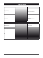
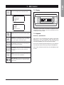
2.7 Safety labels
Identification of the refrigerant - External door
USARE SOLO
R 410A
E
RECUPERARE FLUIDO - NON DISPERDERE NELL’AMBIENTE - REGOLAMENTO CEE N° 3093/94
RECOVER - DO NOT VENT - EEC REGULATION N° 3093/94
SPECIAL ESTER OIL
USE ONLY
Identification of the unit Outside, on the right-hand front column
LAS BOMBAS MONTADAS EN ESTA UNIDAD NO PUEDEN TRABAJAR SIN AGUA
DIE PUMPEN DIESES GERÄTES DÜRFEN NICHT OHNE WASSER BETRIEBEN WERDEN
THE PUMPS ON BOARD OF THIS UNIT CAN NOT WORK WITHOUT WATER
LES POMPES A BORD DE CETTE UNITE NE PEUVENT PAS FONCTIONNER SANS EAU
LE POMPE ABORDO DI QUESTA UNITÀ NON POSSONO FUNZIONARE SENZA ACQUA
Use of filter and flow switch - Adjacent to fittings
E’OBBLIGATORIO L’USO DI FILTRO E FLUSSOSTATO ACQUA
THE USE OF FILTER AND FLOW SWITCH IS MANDATORY
EL USO DEL FILTRO Y DEL INTERRUPTOR DE FLUJO ES OBLIGATORIO
L’UTILISATION DU FILTRE ET DU FLUXOSTAT EST OBLIGATOIRE
DER GEBRAUCH VON FILTER UND STRÖMUNGSWÄCHTER IST
VORGESCHRIEBEN
Lifting point - Base
ACCESSORI inclusi
ACCESSORY enclosed
ZUBEHOR eingeschlossan
ACCESSOIRE ci-inclus
ACCESSORIOS incluidos
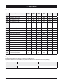
Product code A
Model B
Notified body C
Serial number D
Year of construction E
Refrigerant type F
Refrigerant charge G
High pressure H
Low pressure I
Main supply L
Start up current M
Full load current N
Power input O
Water operation pressure P
Mass Q
IP class R

7
English
2 - Safety
Grounding connection on the
electrical board,
adjacent to the connection
Read the instruction on the
electrical board
On voltage - Adjacent to the
master switch
Fan Danger
Fitting identification - Adjacent to fittings
Sequence phase control on the electrical board
ATTENZIONE
QUESTO COMPRESSORE RICHIEDE UN CORRETTO
SENSO DI ROTAZIONE
RISPETARRE LA CORRETTA SEQUENZA DELLE FASI
THIS COMPRESSOR REQUIRES PROPER DIRECTION
OF ROTATION
CHECK PROPER ELECTRICAL PHASING
KOMPRESSOREN BENÖTIGEN KORREKTES DREHFELD
ELEKTRISCHE ANSCHLÜSSE AUF DREHFELD ÜBERPRÜFEN
CES COMPRESSEURS NECESSITENT UN BON SENS
DE ROTATION
VERIFIER LE CABLAGE DES PHASES
ESTOS COMPRESORES DEBEN FUNCIONAR EN EL
SENTIDO DE ROTACIÓN CORRECTO
COMPROBAR EL CABLEADO DE LAS FASES
CAUTION
ACHTUNG
ATTENTION
ATENCIÓN
Electrical warning
Adjacent to the master switch
ATTENZIONE !
Prima di
aprire togliere
tensione
CAUTION !
Disconnect
electrical
supply before
opening
ACHTUNG !
Vor offnen des
gehauses
hauptschalter
ausschalten
ATENCION !
Cortar la
corrente antes
de abrir
el aparato
ATTENTION !
Enlever
l’alimentation
electrique
avant d’ouvrir
Start-up warning - Outside the door
of the electrical board
ATTENZIONE
inserire le resistenze di riscaldamento olio almeno 12
ore prima di ogni avviamento (se previste)
prima della messa in tensione assicurarsi che le viti dei
circuiti elettrici siano serrate completamente
wArNINg
energize the cranckcase heater for at least 12 hours
before each starting (if fitted)
before tightening-up, to tighten all terminal screws
especially those in main circuit
wArNuNg
olsumpfheizung (falls vorhanden) 12 stunden vor dem
start einschalten
vor inbetriebnahme alle schraubenverbindungen
nachziehen, besonders die elektrischen anschlusse
ATTENTION
alimenter electriquement la resistance de carter au
moins 12 heures avant chaque demarrage (si monte sur
le produit)
avant de demarrer la machine, verifier le serrage de
toutes les bornes a vis, specialement dans le boitier
electrique
ATENTION
atenciÓn alimentar eléctricamente la resistencia de
carter al menos 12 horas antes de cada puesta en
marcha (si esta equipada en la unidad)
antes de la puesta en marcha, comprobar que los
bornes estan bien apretados, especialmente en el
cuadro eléctrico
035B00057-000 MADE IN ITALY
Final Test Certificate - Inside the external door

8
2 - Safety
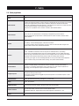
REFRIGERANT DATA SAFETY DATA : R410A
Toxicity Low.
Contact with skin
If sprayed, the refrigerant is likely to cause frost burns. If absorbed by the skin, the danger is very limited;
it may cause a slight irritation, and the liquid is degreasing. Unfreeze the affected skin with water.
Remove the contaminated clothes with great care - in the presence of frost burns, the clothes may stick
to the skin. Wash with plenty of warm water the affected skin.
In the presence of symptoms such as irritation or blisters, obtain medical attention.
Contact with eyes
Vapours do not cause harmful effects. The spraying of refrigerant may cause frost burns.
Wash immediately with a proper solution or with tap water for at least 10 minutes, and then obtain
medical attention.
Ingestion
Very unlikely - should something happen, it will cause frost burns.
Do not induce vomiting. Only if the patient is conscious, wash out mouth with water and give some
250 ml of water to drink. Then, obtain medical attention.
Inhalation
R410A : remarkable concentrations in the air may have an anaesthetic effect, up to fainting.
The exposure to considerable amounts may cause irregular heartbeat, up to the sudden death of the
patient. Very high concentrations may result in the risk of asphyxia, due to the reduction in the oxygen
percentage in the atmosphere. Remove the patient to fresh air and keep warm and at rest.
If necessary, give oxygen. In case of breathing difficulties or arrest, proceed with artificial respiration.
In case of cardiac arrest, proceed with cardiac massage. Then, obtain medical attention.
Recommendations
Semiotics or support therapy is recommended. Cardiac sensitisation has been observed that, in
the presence of circulating catecholamines such as adrenalin, may cause cardiac arrhythmia and
accordingly, in case of exposure to high concentrations, cardiac arrest.
Prolonged exposure
R410A : a study on the effects of exposure to 50,000 ppm during the whole life of rats has identified the
development of benign testicle tumour.
This situation should therefore be negligible for personnel exposed to concentrations equal to or lower
than professional levels.
Professional levels R410A : Recommended threshold : 1000 ppm v/v - 8 hours TWA.
Stability R410A : Not specified.
Conditions to avoid Do not use in the presence of flames, burning surfaces and excess humidity.
Hazardous reactions
May react with sodium, potassium, barium and other alkaline metals.
Incompatible substances: magnesium and alloys with magnesium concentrations > 2%.
Hazardous decomposition
products
R410A : Halogen acids produced by thermal decomposition and hydrolysis.
2.8 Safety regulations

9
English
2 - Safety
REFRIGERANT DATA SAFETY DATA : R410A
General precautions
Do not inhale concentrated vapours. Their concentration in the atmosphere should not exceed the
minimum preset values and should be maintained below the professional threshold. Being more weighty
than the air, the vapour concentrates on the bottom, in narrow areas. Therefore, the exhaust system must
work at low level.
Respiratory system protection
If you are in doubt about the concentration in the atmosphere, it is recommended to wear a respirator
approved by an accident-prevention
Authority, of the independent or oxygen type.
Storage
Cylinders must be stored in a dry and fresh place, free from any fire hazard, far from direct sunlight or
other sources of heat, radiators etc.
Keep a temperature below 50 °C.
Protective clothing Wear overalls, protective gloves and goggles or a mask.
Accidental release measures
It is important to wear protective clothing and a respirator.
Stop the source of the leak, if you can do this without danger. Negligible leaks can be left evaporating
under the sun, providing that the room is well ventilated.
Considerable leaks : ventilate the room. Reduce the leak with sand, earth or other absorbing substances.
Make sure that the liquid does is not channelled into gutters, sewers or pits where the vapours are likely
to create a stuffy atmosphere.
Disposal
The best method is recovery and recycling. If this method is not practicable, dispose according to an
approved procedure, that shall ensure the absorption and neutralization of acids and toxic agents.
Fire fighting information R410A : Not flammable in the atmosphere.
Cylinders The cylinders, if exposed to fire, shall be cooled by water jets; otherwise, if heated, they may explode.
Protective fire fighting equipment In case of fire, wear an independent respirator and protective clothing.
2.8 Safety regulations (continued)

10
2 - Safety
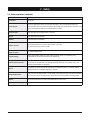
LUBRICANT OIL DATA SAFETY DATA : POLYESTER OIL (POE)
Classification Not harmful.
Contact with skin
May cause slight irritation. Does not require first aid measures. It is recommended to follow usual
personal hygiene measures, including washing the exposed skin with soap and water several times a day.
It is also recommended to wash your overalls at least once a week.
Contact with eyes Wash thoroughly with a suitable solution or tap water.
Ingestion Seek medical advice immediately.
Inhalation Seek medical advice immediately.
Conditions to avoid
Strong oxidising substances, caustic or acid solutions, excess heat.
May corrode some types of paint or rubber.
Protection of the
respiratory system
Use in well ventilated rooms.
Protective clothing
Always wear protective goggles or a mask. Wearing protective gloves is not mandatory, but is
recommended in case of prolonged exposure to refrigerant oil.
Accidental release measures
It is important to wear protective clothing and, especially, goggles.
Stop the source of the leak. Reduce the leak with absorbing substances (sand, sawdust or any other
absorbing material available on the market).
Disposal
The refrigerant oil and its waste will be disposed of in an approved incinerator, in conformity with the
provisions and the local regulations applicable to oil waste.
Fire fighting information
In the presence of hot liquid or flames, use dry powder, carbon dioxide or foam. If the leak is not burning,
use a water jet to remove any vapours and to protect the personnel responsible for stopping the leak.
Cylinders The cylinders exposed to a fire will be cooled with water jets in case of fire.
Fire fighting protective equipment In case of fire, wear an independent respirator.
2.8 Safety regulations (continued)

11
English
3 - Transport, Handling and Storage
AQL/AQH units are supplied fully assembled and tested (except for
accessories supplied loose in the units – absorbers, filter, etc.). They
are ready to be installed and started on the field.
R410A units are only charged with liquid refrigerant and with oil in the
quantity required for operation.
WARNING
The low pressure side of the refrigerating circuit
on R410A units shall be charged by means
of the service valve arranged on the thermal
expansion valve before the device is operated.
3.1 Inspection
The unit shall be immediately inspected upon receipt to find out any
damage since it has been delivered ex works and transported at the
customer’s risk. It is also necessary to make sure that all the parcels
specified on the delivery note have been delivered.
Any damage you may find out shall be immediately reported in writing
to the carrier. Even if the damage is only on the surface, please notify
our local representative too.
The manufacturer disclaims all responsibility for the shipment even if
it has provided for its organisation.
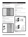
3.2 Handling
AQL/AQH units are designed to be lifted from above, by means of
cables and eyebolts. A spacer shall be arranged between the cables
in order to prevent them from damaging the unit (see the figure
aside).
Before handling the devices, make sure the site you have chosen for
the installation can withstand its weight and support its mechanical
impact.
Avoid touching sharp parts (such as the fins of batteries, for example)
while handling the unit.
WARNING
The unit shall never be placed on rollers.
Act as follows to lift and handle the unit :
n
Insert and secure the eyebolts into the frame holes which have
been marked on purpose.
n
Connect the cables to the eyebolts.
n
Insert the spacer between the cables.
n
Provide for hooking at the centre of gravity of the device.
n
Cables shall have such a length that the angle they form with the
horizon when under tension is not less than 45°.
Space requirements request to handling
Protect cabinet during lifting
Holes Ø 30 mm
WARNING
While lifting and handling the unit, pay attention.
Otherwise, you might damage the finned block of
the coils arranged on both sides of the unit. The
sides of the unit shall be protected by cardboard
or plywood sheets.

12
3 - Transport, Handling and Storage
WARNING
Until the unit is ready for operation, do not
remove the plastic envelope and the coil
protections which are intended to prevent dirt,
dust and any foreign matter from penetrating
into the unit through the inlets of fans or from
damaging the external surfaces.
3.3 Anchoring
It is not essential to secure the unit to the foundations, unless in areas
where there is a serious risk of earth-quake, or if the appliance is
installed on the top of a steel frame.
3.4 Storage
If the unit is to be stored before the installation for some time, take
at least the following precautions to prevent damage, corrosion and/
or deterioration :
n
Make sure all openings, such as for example water connections,
are well plugged and sealed.
n
Never store the units in a room where temperature is above
50 °C (R410A units) or where the units are directly exposed to
the sunlight.
n
Minimum storage temperature is -25 °C.
n
It is recommended to leave the finned coils covered to protect
them against any risk of corrosion, especially if building works
are still in progress.
n
Store the units in areas where minimum activity is likely to take
place in order to avoid any risk of accidental damage.
n
Never use steam to clean the unit.
n
Remove all the keys required to have access to the control panel
and give them to the person in charge of the field.
It is also recommended to provide for visual inspections at regular
intervals.

13
English
4 - Installation
4.1 Installation Site
DANGER
Before installing the unit, make sure that
the building structure and/or the supporting
surface can withstand the weight of the
device. The weights of the units are detailed
by Chapter 9 of this manual.
These units have been designed to be installed on the floor, in the
open air. As a standard, they are equipped with rubber vibration-
damping supports which shall be arranged in the middle, beneath
the supporting plates.
When the unit is to be installed on the ground, provide for a concrete
bedplate which shall assure a uniform distribution of the weights. No
special subbase is generally required.
When selecting the installation site, never forget to consider as
follows :
n
The longitudinal axis of the unit shall be parallel to the direction of
the prevailing winds so as to assure a uniform air distribution on
finned exchangers.
n
The unit shall never be installed in the proximity of chimneys for
the discharge of boiler flue gases.
n
The unit shall never be installed downwind of sources of grease
contaminated air, such as for example the outlets of large-
kitchen extractors. Otherwise, grease might build up on the fins
of refrigerant / air exchangers or condensers, act as a fixing
agent for any sort of atmospheric impurity and rapidly cause the
exchangers to clog.
n
The unit shall never be installed in areas exposed to heavy
snowfalls.
n
The unit shall never be installed in areas exposed to flooding or
beneath drip stones, etc.
n
The unit shall never be installed in narrow inner court yards or in
any other restricted space where the noise may be reflected by
the walls or where the air expelled by the fans may short-circuit
on the refrigerant/air heat exchangers or condensers.
n
The installation site shall be characterised by the presence of
the space required for air circulation and for the performance of
maintenance operations (see chapter 9 for further details).
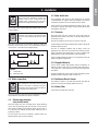
4.2 External Water Circuit
WARNING
The external water circuit shall guarantee a
constant water flow rate through the circulating
refrigerant/water heat exchanger (evaporator)
under steady operating conditions and in case
of a load variation.
The circuit shall be composed by the following elements :
n
A circulation pump which can ensure the necessary flow rate and
head.
n
The total content of the primary water circuit shall never be
lower than 2.5 lt/kW in terms of refrigerating capacity. If the total
water volume in the primary circuit should be unable to reach
such a value, an additional heat-insulated storage tank should be
installed. This tank is intended to avoid any repetitive start of the
compressor.
n
A membrane expansion tank complete with a safety valve and a
drain which shall be visible.
NOTE
The expansion tank shall be dimensioned in
such a way that it can absorb a 2% expansion
of the total volume of the water in the plant
(exchanger, pipelines, uses and storage tank,
if available). The expansion tank shall never
be insulated when the circulating fluid is not
flowing through it.
A differential pressure switch is mounted as a standard. It will stop
the unit whenever it senses a load loss through the heat exchanger
which may result in a flow rate problem.
In addition :
n
Install on/off valves (accessory) on the lines at the inlet and outlet
of the manifolds of the exchangers (evaporator).
n
Arrange a by-pass complete with an on/off valve between the
manifolds of the heat exchangers.
n
Arrange air vent valves at the high points of the water lines.
n
Arrange drain points complete with plugs, clocks, etc. in the
proximity of the low points of the water lines.
n
Insulate the water lines to prevent the heat from blowing back into
the unit.

14
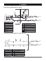
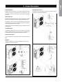
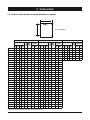
External water circuit AQL/AQH 20 to 35 - R410A
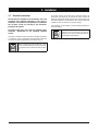
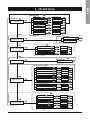
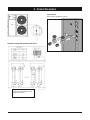
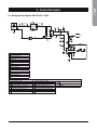
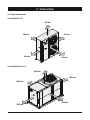
External water circuit AQL/AQH 40 to 75 - R410A - Basic Unit
4 - Installation
1
B
A
10
5
G
G
9
11
11
12
12
13
INLET
OUTLET
FS
I
8
E
D
8
components
1 Plate heat exchanger
5 Water filter
8 Pressure point/drain valve
9 Water outlet
10 Water inlet
11 Globe valve
12 Flexible pipes
13 By-pass valve
safety/control devices
a Inlet water temperature sensor
B Outlet water temperature sensor
d Vent valve (105 mbar)
e Water safety valve (3 bar)
fs Flow switch
G Thermometer
i Hydrometer
Unit side
safety/control devices
a Inlet water temperature sensor
B Outlet water temperature sensor
c Water differential pressure switch (105 mbar)
d Vent valve
e Water safety valve (3 bar)
f Manometer
fs Flow switch
G Thermometer
i Hydrometer
Unit side
y Water drain
10
10
9 9
13
12
12 11
11
4
5
3
8
6
3
Y
HYDROKIT
INLET
OUTLET
Y
Y
2
3
1
7
FS
F
E
E
D
D
C
A
B
I
G
G
components
1 Plate heat exchanger
2 Pump
3 Draining valve
4 Water buffer tank
5 Water filter
6 Automatic water charging valve
7 Pressure expansion tank
8 Water charging line
9 Water outlet
10 Water inlet
11 Globe valve
12 Flexible pipes
13 By-pass valve

15
English
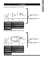
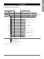
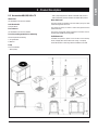
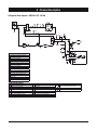
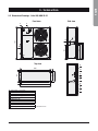
External water circuit AQL/AQH 40 to 75 - R410A - 1 Pump
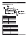
External water circuit AQL/AQH 40 to 75 - R410A - 2 Pump
4 - Installation
8
D
2
E
8
I
FS
OUTLET
INLET
13
12
12
11
11
9
G
G
5
10
A
B
1
7
D
components
1 Plate heat exchanger
2 Pump
5 Water filter
7 Pressure expansion tank
8 Pressure point/drain valve
9 Water outlet
10 Water inlet
11 Globe valve
12 Flexible pipes
13 By-pass valve
safety/control devices
a Inlet water temperature sensor
B Outlet water temperature sensor
d Vent valve (105 mbar)
e Water safety valve (3 bar)
fs Flow switch
G Thermometer
i Hydrometer
Unit side
D
7
1
B
A
10
5
G
G
9
11
11
12
12
13
INLET
OUTLET
FS
I
8
E
D
8
2
2
6
6
11 11
1111
components
1 Plate heat exchanger
2 Pump
5 Water filter
6 Non-return valve
7 Pressure expansion tank
8 Pressure point/drain valve
9 Water outlet
10 Water inlet
11 Globe valve
12 Flexible pipes
13 By-pass valve
safety/control devices
a Inlet water temperature sensor
B Outlet water temperature sensor
d Vent valve (105 mbar)
e Water safety valve (3 bar)
fs Flow switch
G Thermometer
i Hydrometer
Unit side

16
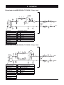
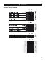
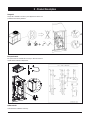
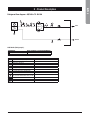
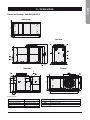
External water circuit AQL/AQH 40 to 75 - R410A - 1 Pump + tank
External water circuit AQL/AQH 40 to 75 - R410A - 2 Pump + tank
4 - Installation
2
8
D
E
8
I
FS
OUTLET
INLET
13
12
12
11
11
9
G
G
5
10
A
B
1
7
D
3
Y
4
1111
components
1 Plate heat exchanger
2 Pump
3 Draining valve
4 Water buffer tank
5 Water filter
7 Pressure expansion tank
8 Pressure point/drain valve
9 Water outlet
10 Water inlet
11 Globe valve
12 Flexible pipes
13 By-pass valve
safety/control devices
a Inlet water temperature sensor
B Outlet water temperature sensor
d Vent valve (105 mbar)
e Water safety valve (3 bar)
fs Flow switch
G Thermometer
i Hydrometer
Unit side
y Water drain
4
Y
3
D
7
1
B
A
10
5
G
G
9
11
11
12
12
13
INLET
OUTLET
FS
I
8
E
D
8
2
2
11 11
1111
6
6
components
1 Plate heat exchanger
2 Pump
3 Draining valve
4 Water buffer tank
5 Water filter
6 Non-return valve
7 Pressure expansion tank
8 Pressure point/drain valve
9 Water outlet
10 Water inlet
11 Globe valve
12 Flexible pipes
13 By-pass valve
safety/control devices
a Inlet water temperature sensor
B Outlet water temperature sensor
d Vent valve (105 mbar)
e Water safety valve (3 bar)
fs Flow switch
G Thermometer
i Hydrometer
Unit side
y Water drain

17
English
4 - Installation
WARNING
Before filling the installation, remove any
impurity, such as sand, crushed stones and
welding scales, coating drops and any other
material which might damage the evaporator.
It is advisable to flush with disposable water bypassing the exchanger
to avoid clogging.
NOTE
The water used to fill the circuit shall be treated
in such as way that the pH will have the correct
value.
When two or several units are connected in parallel, to balance the
load losses of the various circuits, it is recommended to execute a
“reverse return” connection (see the diagram below).
UNIT 1
UNIT 2
Legend
S On/Off valves
VG Balancing valves
4.3 Water connections
WARNING
The attachments at the water inlet and outlet
shall be connected in compliance with the
instructions which can be found on the labels in
the proximity of the attachments.
Connect the water lines of the plants with the attachments of the unit
whose diameters and positions are shown in Chapter 9.
4.4 Defrost water drainage
(only for AQH units)
When heat pump units work in heating mode, during defrosting
cycles, they may discharge water from the base. This is why the
units should be installed at least 200 mm above the floor level, so
as to allow the free drainage of waste water, without the risk of
producing ice banks.
The heat pump units must be installed in positions where the
defrosting water cannot create any damage.
4.5 Water buffer tank
The accumulation tank which has been designed to be mounted
on AQL/AQH units is complete with all the hydraulic and electrical
components required for the correct operation of the system.
These systems are carefully assembled and tested at works. They
are ready for operation after having correctly realised all electrical
and hydraulic connections.
4.5.1 Features
Units AQL 20-35 have one single tank. The kit will include an
Antifreeze Electric Heater, a drain valve, an automatic filling unit and
an automatic air vent.
No pump is arranged on the kit since it is mounted on the unit.
A tank arranged for mounting a heating booster resistance kit may be
optionally required (5 traps).
The tank is completely insulated with 30 Kg/m
3
closed cell
polyethylene in a silver colour and enclosed by a bearing structure
made of passivated and painted plates. The box is equipped with
bulkheads which can be easily opened for internal inspection.
The kit is installed beneath the chiller. It is an integral part of the unit
without changing the support area.
4.5.2 Supplied Material
The kits will be supplied with pipelines ready for installation. An
antifreeze resistance with wiring, an automatic water filling valve, a
3 bar safety valve, a drain valve and a vent valve have already been
assembled.
Hydrokit is shipped with a film to protect it from atmospheric agents.
Packaging has been designed in order to stack it up.
4.5.3 Antifreeze Electric Heater
The antifreeze resistance of the tank (TEH) shall be wired with the
panel as it is shown by the diagram attached to the unit.
4.5.4 Water Filter
The kit will use the water filter of the unit.

18
4.6 Power supply
DANGER
Before carrying out any operations on the
electrical system, make sure that the unit is
deenergized.
DANGER
It is important that the appliance is grounded.
WARNING
The company in charge of the installation shall
conform to the standards applicable to outdoor
electrical connections.
The manufacturer may not be held liable for any damage
and/or injury caused by failure to comply with these
precautions.
The unit conforms to EN 60204-1.
The following connections shall be provided :
n
A 3-phase and grounding connection for the power supply circuit.
n
The electrical distribution system shall meet the power absorbed
by the appliance.
n
The disconnecting and magnetothermal switches must be sized
to control the starting current of the unit.
n
The power supply lines and the insulation devices must be
designed in such a way that every line independent.
n
It is recommended to install differential switches, to prevent any
damage caused by phase drops.
n
The fans and compressors are supplied through contactors
controlled from the control panel.
n
Each motor is provided with an internal safety thermal device and
external fuses.
n
The power supply cables must be inserted into dedicated
openings on the front of the unit, and the will enter the electrical
board through holes drilled on the bottom of the board.
4 - Installation
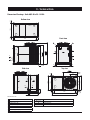
CAUTIONS
The unit + tank system shall be equipped with a filter. Use the filter
+ union as it is shown by Figure 1.
Positioning rubber
shock absorbers
Water filter
position
Figure 1
4.5.5 Installation Procedure
For the size 20-35 the hydrokit shall be arranged beneath the unit. It
will not change its overall dimensions (Figure 1).
Arrange the rubber shock absorbers beneath the kit before providing
for its connection.
Provide for the hydraulic and electrical connections. Doing that,
observe the diameters shown by the quoted drawings.
The wiring for the standard antifreeze resistance is arranged as it is
shown by . The resistance is connected with the main terminal box.
See the wiring diagram attached to the unit for the correct execution
of the electrical connections.
Install the water filter as it is shown by Figure 1.
Instead for the size 40-75 the Hydrokit if required, will be installed
on the unit.
Page is loading ...
Page is loading ...
Page is loading ...
Page is loading ...
Page is loading ...
Page is loading ...
Page is loading ...
Page is loading ...
Page is loading ...
Page is loading ...
Page is loading ...
Page is loading ...
Page is loading ...
Page is loading ...
Page is loading ...
Page is loading ...
Page is loading ...
Page is loading ...
Page is loading ...
Page is loading ...
Page is loading ...
Page is loading ...
Page is loading ...
Page is loading ...
Page is loading ...
Page is loading ...
Page is loading ...
Page is loading ...
Page is loading ...
Page is loading ...
Page is loading ...
Page is loading ...
Page is loading ...
Page is loading ...
Page is loading ...
Page is loading ...
Page is loading ...
Page is loading ...
Page is loading ...
Page is loading ...
Page is loading ...
Page is loading ...
Page is loading ...
Page is loading ...
Page is loading ...
Page is loading ...
Page is loading ...
Page is loading ...
Page is loading ...
Page is loading ...
Page is loading ...
Page is loading ...
Page is loading ...
Page is loading ...
Page is loading ...
Page is loading ...
-
 1
1
-
 2
2
-
 3
3
-
 4
4
-
 5
5
-
 6
6
-
 7
7
-
 8
8
-
 9
9
-
 10
10
-
 11
11
-
 12
12
-
 13
13
-
 14
14
-
 15
15
-
 16
16
-
 17
17
-
 18
18
-
 19
19
-
 20
20
-
 21
21
-
 22
22
-
 23
23
-
 24
24
-
 25
25
-
 26
26
-
 27
27
-
 28
28
-
 29
29
-
 30
30
-
 31
31
-
 32
32
-
 33
33
-
 34
34
-
 35
35
-
 36
36
-
 37
37
-
 38
38
-
 39
39
-
 40
40
-
 41
41
-
 42
42
-
 43
43
-
 44
44
-
 45
45
-
 46
46
-
 47
47
-
 48
48
-
 49
49
-
 50
50
-
 51
51
-
 52
52
-
 53
53
-
 54
54
-
 55
55
-
 56
56
-
 57
57
-
 58
58
-
 59
59
-
 60
60
-
 61
61
-
 62
62
-
 63
63
-
 64
64
-
 65
65
-
 66
66
-
 67
67
-
 68
68
-
 69
69
-
 70
70
-
 71
71
-
 72
72
-
 73
73
-
 74
74
-
 75
75
-
 76
76


Airwell AQC 40-75 Installation and Maintenance Manual
- Category
- Heat pumps
- Type
- Installation and Maintenance Manual
Ask a question and I''ll find the answer in the document
Finding information in a document is now easier with AI
Related papers
Other documents
-
Campbell Hausfeld PA212503AV Operating instructions
-
 SystemAir SYSCROLL 450 Air EVO CO Owner's manual
-
 SystemAir AQWR Installation and Maintenance Manual
-
 SystemAir AQVH 140 Owner's manual
-
SystemAir VLH 804 Owner's manual
-
 TripleAqua 3PL40 Installation & Maintenance Manual
-
 SystemAir SYSCROLL 20 Air EVO HP Owner's manual
-
Swegon TEAL Owner's manual
-
Western Kappa Rev FC Installation and Operating Instructions
-


