
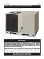
SINGLE PACKAGE CONVERTIBLE AIR CONDITIONER
USER’S MANUAL / INSTALLATION INSTRUCTIONS
Please read this information thoroughly and become familiar with the capabilities and
use of your appliance before attempting to operate or maintain this unit. Keep this
literature where you have easy access to it in the future. If a problem occurs, check the
instructions and follow recommendations given. If these suggestions don’t eliminate
your problem, call your servicing contractor.
These instructions are primarily intended to assist qualifi ed individuals experienced in
the proper installation of this appliance. Some local codes require licensed installation/
service personnel for this type of equipment. Please read all instructions carefully before
starting the installation.
DO NOT DESTROY. PLEASE READ CAREFULLY AND
KEEP IN A SAFE PLACE FOR FUTURE REFERENCE.
IMPORTANT
Premium Model Shown
P6SD SERIES 13 SEER

2

3
Safety Information ......................................................5
General Information ...................................................6
Pre - Installation Check .............................................6
Locating the Air Conditioner ......................................6
Field Connections for Electrical Power
Supply .......................................................................6
Air Ducts ...................................................................6
Unconditioned Spaces ...........................................6
Acoustical Duct Work .............................................6
Air Filter Requirements ............................................7
Air Conditioner Installation .......................................7
Packaging Removal .................................................7
Rigging and Hoisting ................................................7
Minimum Clearance Requirements ...........................7
Ground Level .............................................................7
Rooftop ......................................................................8
Horizontal to Downfl ow Conversion ..........................8
Removal of Internal Filter Rack .................................8
Installing Filters in the Filter Rack .............................8
Removing Filters from the Filter Rack .......................8
Condensate Drain ....................................................8
Electrical Wiring .........................................................9
Pre - Electrical Checklist ...........................................9
Line Voltage ..............................................................9
Grounding .................................................................9
Unbalanced 3-Phase Supply Voltage .....................10
Thermostat Connections .........................................10
Blower Speed ..........................................................10
PSC Motor - 208/230V ......................................... 11
PSC Motor - 460V ................................................ 11
Fixed Torque ECM Motor ..................................... 11
Optional Outdoor Thermostat ................................. 11
Optional Electric Heater Kits ................................... 11
Startup & System Check ......................................... 12
Pre - Start Checklist ................................................ 12
Start-up Procedure .................................................. 12
Air Circulation ....................................................... 12
System Cooling .................................................... 12
System Heating .................................................... 12
Refrigerant Charging ............................................... 12
Charging an R-410A Unit in AC Mode..................... 12
Air Conditioner Maintenance .................................. 14
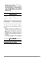
Figures & Tables ....................................................... 14
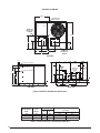
Figure 9. P6SD Air Conditioner Dimensions ........ 14
Table 4. Center of Gravity & Shipping Weights .... 14
Electrical Information .............................................. 15
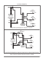
Figure 10. A.C. T-Stat Connections - 230V .......... 15
Figure 11. A.C. T-Stat Connections - 460V .......... 15
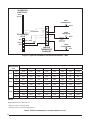
Table 5. A.C. Blower Curves ................................ 16
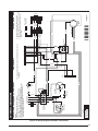
Figure 12. Wiring Diagram - PSC Motor -
Three Phase - 208/230V ..................... 17
Figure 13. Wiring Diagram - Fixed Torque Motor -
Three Phase - 208/230V ..................... 18
Figure 14. Wiring Diagram - PSC Motor -
Single Phase - 208/230V .................... 19
Figure 15. Wiring Diagram - Fixed Torque Motor -
Single Phase - 208/230V .................... 20
Figure 16. Wiring Diagram - Fixed Torque Motor -
Three Phase - 460V ............................ 21
Figure 17. Wiring Diagram - PSC Motor -
Three Phase - 460V ............................ 22
Cooling Charging Charts ......................................... 23
Figure 18. Charging Chart for 3 Ton Units ........... 23
Figure 19. Charging Chart for 4 Ton Units ........... 23
Figure 20. Charging Chart for 5 Ton Units ........... 24
USER INFORMATION
INSTALLER INFORMATION
Safety Information ......................................................4
About the Air Conditioner .........................................4
Operating Instructions...............................................4
Cooling Operation .....................................................4
Heating Operation .....................................................4
Turning the Air Conditioner Off .................................4
Oper. the Indoor Blower Continuously ......................4
Air Conditioner Maintenance ....................................4
Regular Cleaning ......................................................4
Before You Call a Technician ....................................4
WARRANTY INFORMATION
A warranty certifi cate with full details is included with the
Air Conditioner. Carefully review these responsibilities with
y o u r d e a l e r o r s e r v i c e c o m p a n y. T h e m a n u f a c t u r e r w i l l n o t
be responsible for any costs found necessary to correct
problems due to improper setup, improper installation,
adjustments, improper operating procedure on the part
of the user, etc. Some specifi c examples of service calls
which are not included in the limited warranty are:
• Correcting wiring problems in the electrical circuit
supplying the Air Conditioner.
• Resetting circuit breakers or other switches.
• Adjusting or calibrating of thermostat.

4
ABOUT THE AIR CONDITIONER
The P6 Series single packaged convertible air conditioner
is a high effi cient self contained cooling unit that will cool
your home year round and provide energy saving comfort.
Additional features and benefi ts of the P6 air conditioner
include:
• Indoor and outdoor coils are designed to optimize heat
transfer, minimize size and cost, and increase durability
and reliability.
• Environmentally friendly R-410A Refrigerant.
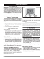
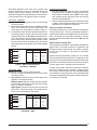
OPERATING INSTRUCTIONS
Cooling Operation
1. Set the thermo st at ’s system mo d e to C O OL or AUTO
and change the fan mode to AUTO. See Figure 1.
2. Set the temperature selector to the desired
temperature level. The outdoor fan, compressor, and
blower motor will all cycle on and off to maintain the
indoor temperature at the desired cooling level.
Heating Operation
(If optional heat accessory is installed)
1. Set the thermostat ’s system mode to HEAT or AUTO
and change the fan mode to AUTO. See Figure 1.
2. Set the temperature selector to a desired temperature
level. The indoor blower will cycle on and off to maintain
the indoor temperature at the desired heating level.
Turning the Air Conditioner OFF
Change the thermostat’s system mode to OFF and the fan
mode to AUTO (See Figure 1). NOTE: The system will not
operate, regardless of the temperature selector setting.
Operating the Indoor Blower Continuously
The continuous indoor blower operation is typically used to
circulate the indoor air to equalize a temperature unbalance
due to a sun load, cooking, or fi replace operation.
Set the thermostat fan mode to ON (Figure 1). The indoor
blower starts immediately, and will run continually until
the fan mode is reset to AUTO.
SAFETY INFORMATION
IMPORTANT: Please read all instructions before servicing
this equipment. Pay attention to all safety warnings and
any other special notes highlighted in the manual. Safety
markings are used frequently throughout this manual to
designate a degree or level of seriousness and should not
be ignored. WARNING indicates a potentially hazardous
situation that if not avoided, could result in personal injury
or death. CAUTION indicates a potentially hazardous
situation that if not avoided, may result in minor or moderate
injury or property damage.
USER INFORMATION
Figure 1. Digital Thermostat
Fan
Mode
Temperature
Selector
System
Mode
The continuous indoor blower operation can be obtained
with the thermostat system mode set in any position,
including OFF.
AIR CONDITIONER MAINTENANCE
Proper maintenance is most important to achieve the best
performance from the appliance and should be performed
frequently at the beginning of each air conditioning season.
WARNING:
Your Air Conditioner contains liquid and gaseous
refrigerant under pressure. Installation and
servicing should only be attempted by qualifi ed,
trained personnel thoroughly familiar with the
equipment and safe responsible refrigerant
handling procedures. Failure to comply with
this warning could result in equipment damage,
personal injury, or death.
• Keep the outdoor unit clean. Hose off periodically and
keep unit fi ns clear of leaves and grass clippings.
• Keep the outdoor unit clear of obstructions.
DO NOT obstruct airfl ow with tall plants or shrubs. DO
NOT store gasoline or other fl ammable materials on
or near the outdoor unit.
• Never operate the appliance without a fi lter installed in
the return air duct. Inspect fi lters frequently and replace
when necessary with fi lter of same dimensional size.
Before You Call a Technician:
• Check the thermostat setting. Make sure the system
mode and temperature settings are correct.
• Check the electrical panel for tripped circuit breakers.
• Check the fi lters for dust accumulation.
• Check the outdoor unit and make sure it is clean and
not covered with grass or leaves.

5
INSTALLER INFORMATION
SAFETY INFORMATION
IMPORTANT: Safety markings are used frequently
throughout this manual to designate a degree or level
of seriousness and should not be ignored. WARNING
indicates a potentially hazardous situation that if
not avoided, could result in personal injury or death.
CAUTION indicates a potentially hazardous situation that
if not avoided, may result in minor or moderate injury or
property damage.
WARNING:
These units are fully charged with R-410A
refrigerant and ready for installation. When
a system is installed according to these
instructions, no refrigerant charging is required.
If repairs make it necessary for evacuation
and charging, it should only be attempted by
qualifi ed, trained personnel thoroughly familiar
with this equipment. Some local codes require
licensed installation service personnel to
service this type of equipment. Under no
circumstances should the homeowner attempt
to install and/or service this equipment. Failure
to comply with this warning could result in
equipment damage, personal injury, or death.
WARNING:
The safety information listed below must be
followed during the installation, service, and
operation of this unit. Unqualifi ed individuals
should not attempt to interpret these instructions
or install this equipment. Failure to follow safety
recommendations could result in possible
damage to the equipment, serious per
sonal
injury or death
.
• The installer must comply with all local codes and
regulations which govern the installation of this type
of equipment. Local codes and regulations take
precedence over any recommendations contained in
these instructions. Consult local building codes and
the National Electrical Code (ANSI CI) for special
installation requirements.
• This equipment contains liquid and gaseous refrigerant
under high pressure. Installation or servicing should only
be performed by qualifi ed trained personnel thoroughly
familiar with this type equipment.
• All electrical wiring must be completed in accordance
with local, state and national codes and regulations
and with the National Electric Code (ANSI/NFPA 70)
or in Canada the Canadian Electric Code Part 1 CSA
C.22.1.
• Installation of equipment may require brazing
operations. Installer must comply with safety codes
and wear appropriate safety equipment (safety glasses,
work gloves, fi re extinguisher, etc.) when performing
brazing operations.
• Install this unit only in a location and position as specifi ed
on page 6. This unit is designed only for outdoor
installations and should be located with consideration
of minimizing the length of the supply and return ducts.
Consideration should also be given to the accessibility
of fuel, electric power, service access, noise, and shade.
• Follow all precautions in the literature, on tags, and
on labels provided with the equipment. Read and
thoroughly understand the instructions provided with
the equipment prior to performing the installation and
operational checkout of the equipment.
WARNING:
Improper installation, service, adjustment, or
maintenance may cause explosion, fi re, electrical
shock or other hazardous conditions which may
result in personal injury or property damage.
Unless otherwise noted in these instructions,
only factory authorized kits or accessories may
be used with this product.
CAUTION:
This unit uses refrigerant R-410A. DO NOT use
any other refrigerant in this unit. Use of another
refrigerant will damage the unit.
WARNING:
Shut off all electrical power to the unit before
performing any maintenance or service on the
system. Failure to comply may result in personal
injury or death.
WARNING:
Do not place combustible material on or against
the unit cabinet. Do not place combustible
materials, including gasoline and any other
fl ammable vapors and liquids, in the vicinity of
the unit.

6
Locating the Air Conditioner
• Survey the job site to determine the best location for
mounting the outdoor unit.
• Choose an appropriate location that minimizes the
length of the supply and return air ducts.
• Avoid overhead obstructions, poorly ventilated areas,
and areas subject to accumulation of debris.
• Suffi cient clearance for unobstructed airfl ow through the
outdoor coil must be maintained in order to achieve rated
performance. See Figure 2 for minimum clearances
to obstructions.
Field Connections for Electrical Power Supply
• All wiring must comply with current provisions of the
National Electrical Code (ANSI/NFPA 70) and with
applicable local codes having jurisdiction.
• The minimum size of electrical conductors and circuit
protection must be in compliance with information listed
on the outdoor unit data label.
• Electrical power supplied to the unit must be adequate
for proper operation of the equipment. The system
must be wired and provided with circuit protection in
accordance with local building codes.
Air Ducts
This unit is designed only for use with a supply and return
duct. Air ducts should be installed in accordance with
the standards of the National Fire Protection Association
Standard for Installation of Air Conditioning Systems
(NFPA 90A), Standard for Installation of Residence Type
Warm Air Heating and Air Conditioning Systems (NFPA
90B), and all applicable local codes. NFPA publications
are avaialable by writing to: National Fire Protection
Association, Batterymarch Park, Quincy, ME 02269 or
visit www.NFPA.org on the web.
• Design the duct work according to methods described
by the Air Conditioning Contractors of America (ACCA).
• The ducts must be properly sized and not exceed .2”
W.C. pressure drop at 400 scfm per nominal ton of
cooling capacity.
• Duct work should be attached directly to the unit fl anges
for horizontal applications.
• If roof curb is installed, the ducts must be attached to
the curb hangers, not the unit.
Unconditioned Spaces
All duct work passing through unconditioned space must
b e pr o p er ly i ns ul a t ed to mi n im iz e d uc t l o s se s a n d p reve nt
condensation. Use insulation with an outer vapor barrier.
Refer to local codes for insulation material requirements.
Acoustical Duct Work
Certain installations may require the use of acoustical
lining inside the supply duct work.
• Acoustical insulation must be in accordance with the
current revision of the Sheet Metal and Air Conditioning
Contractors National Association (SMACNA)
application standard for duct liners.
GENERAL INFORMATION
Packaged Air Conditioner units are ready for easy and
immediate installation on rooftops or ground level slabs.
Units are shipped for horizontal duct connections and
can be easily converted for downfl ow applications. This
air conditioner is designed only for outdoor installations.
This unit has been designed and tested for capacity and
effi ciency in accordance with A.R.I. Standards. This
unit will provide many years of safe and dependable
comfort, providing it is properly installed and maintained.
With regular maintenance, this unit will operate reliably
year after year. Abuse, improper use, and/or improper
maintenance can shorten the life of the appliance and
create unsafe hazards.
Pre - Installation Check
Before you install this unit, the cooling load of the area
to be conditioned must be calculated and a system of
the proper capacity selected. It is recommended that
the area to be conditioned be completely insulated
and vapor sealed.
Check the electrical supply and verify the power supply
is adequate for unit operation. If there is any question
concerning the power supply, contact the local power
company.
All units are securely packed at the time of shipment
and upon arrival should be carefully inspected for
damage prior to installing the equipment at the job
site. Verify coil fi ns are straight. If necessary, comb fi ns
to remove fl attened or bent fi ns. Claims for damage
(apparent or concealed) should be fi led immediately
with the carrier.
Please consult your dealer for maintenance information
and availability of maintenance contracts. Please read
all instructions before installing the unit.
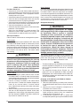
Minimum Required
Clearances to Obstructions
0"
36"
36"
36"
TOP OF UNIT
TO BE
UNOBSTRUCTED
36” For Coil Only
Figure 2. Clearance Requirements

7
• Duct lining must be UL classifi ed batts or blankets with
a fi re hazard classifi cation of FHC-25/50 or less.
• Fiber duct work may be used in place of internal duct
liners if the fi ber duct work is in accordance with the
current revision of the SMACNA construction standard
on fi brous glass ducts. Fibrous duct work and internal
acoustical lining must be NFPA Class 1 air ducts when
tested per UL Standard 181 for Class 1 ducts.
Air Filter Requirements
WARNING:
Never operate the unit without a fi lter in place.
Dust and lint could accumulate on internal parts,
resulting in loss of effi ciency, equipment damage
and possible fi re. Replace disposable fi lters with
the same type and size.
• Air fi lter(s) are not supplied and must be installed in
the unit or in the return air system by the installer. Only
three phase units are equipped with an internal fi lter
rack assembly.
• If using an Economizer or Fresh Air Equipment, the
factory installed fi lter rack must be removed prior to
installation. See page 8 for removal instructions.
• All return air must pass through the fi lters before
entering the unit. Recommended fi lter sizes are listed in
Table 1. NOTE: It is important that all fi lters be kept clean
and replaced frequently to ensure proper operation of
unit. Dirty or clogged fi lters will reduce the effi ciency
of the unit and result in unit shutdowns.
• Air fi lter pressure drop must not exceed 0.08 inches
WC. When replacing the air fi lters, a suitable air fi lter
must be installed upstream of the evaporator coil of
the return air system.
• Downflow Installations require an internal filter
accessory kit to be installed.
• Horizontal Installations require the air fi lter system be
installed in the return air ductwork.
Unit Size Internal Filter Size
P6SD-X36
P6SD-X48
(2) 16” x 25” x 1”
or
(2) 16” x 25” x 2”
P6SD-X60
(2) 18” x 25” x 1”
or
(2) 18” x 25” x 2”
Table 1. Internal Filter Size Requirements.
AIR CONDITIONER INSTALLATION
Packaging Removal
Remove the shipping carton and User’s Manual from
the equipment. Take care not to damage the tubing
connections when removing the carton. For rooftop
installations, remove and discard the two supports
attached beneath the unit.
Rigging and Hoisting
WARNING:
To avoid the risk of property damage, personal
injury, or death, it is the rigger’s responsibility
to ensure that whatever means are used to hoist
the unit are safe and adequate:
• The lifting equipment must be adequate for the
load. Refer to Table 4 (page 14) for unit weights.
• The unit must be lifted from the holes in the
base rails using cables or chains.
• Spreader bars are required to protect the unit
and ensure even loading.
• Keep the unit in an upright position at all times.
The rigging must be located outside the units
center of gravity. Refer to Figure 9 (page 14)
for locating the center of gravity.
• All panels must be securely in place during
rigging and hoisting.
Minimum Clearance Requirements
P6SD units are certifi ed as cooling equipment for
outdoor installation only. Figure 2 (page 6) displays the
minimum clearances to obstructions for both Downfl ow
and Horizontal discharge.
Units may be installed on wood fl ooring or on Class A,
B, or C roof covering material when used with bottom
supply and return air ducts. If using bottom discharge
with return air ducts, a roof curb must be installed prior
to unit installation. See Rigging and Hoisting section for
setting of the unit.
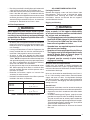
Ground Level
Ground level installations must be located according to
local building codes or ordinances and these requirements:
• Clearances must be in accordance with those shown
in Figure 2.
• A suitable mounting pad (Figure 3, page 8) must be
provided and separate from the building foundation.
The pad must be level to ensure proper condensate
disposal and strong enough to support the unit’s weight.
The slab height must be a minimum of 2” (5cm) above
grade and with adequate drainage.
• Allow suffi cient clearances for access to the internal
fi lter rack.

8
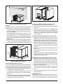
Rooftop
Rooftop installations must be located according to local
building codes or ordinances and these requirements:
• The roof must be capable of handling the weight of the
unit. For unit weights, see Table 4 (page 14). Reinforce
the roof if necessary.
• The appropriate accessory roof curb (Figure 4) must
be installed prior to unit installation. The roof curb
must be square and level to ensure proper condensate
drainage. Please follow all instructions provided
with the kit.
• Secure roof curb or frame to roof using acceptable
mechanical methods per local codes. NOTE: Make sure
the two supports beneath the unit have been removed.
Roof
Curb
Figure 4. Roof Top Installation
2”
Figure 3. Ground Level Installation
Removal of Internal Filter Rack (3 Phase Only)
1. Remove the return air panel from the unit.
2. Remove the height adjustment screw from the inside
of the rack.
3. Remove (1) screw securing the assembly to the
coil located on the left leg of the rack. NOTE: The
assembly can now be easily collapsed and removed
from the unit. See Figure 5 for fi lter rack securing
screw locations.
Installing Filters in the Filter Rack (3 Phase Only)
1. Remove access panel screws from return air panel.
(Hint: Loosen the unit’s top panel screws near the
top edge of the access panel. The access panel was
designed to be captured underneath the top panel.)
2. Slide the fi rst fi lter between both guide channels of
fi l t e r r a c k a n d allow the fi lter to drop easily into place.
3. Verify the bottom of the fi lter is within the channels
of the rack.
4. Slide the 2nd fi lter between both guide channels of
fi l t e r r a c k .
5. Verify the bottom of the fi lter is within the channels
of the rack.
6. Replace access cover by sliding the top edge of panel
under the lip of the unit’s Top Panel. Secure access
panel by replacing the screws.
Removing Filters from Filter Rack (3 Phase Only)
1. Remove access panel screws from return air panel.
(Hint: Loosen the unit’s top panel screws near the
top edge of the access panel. The access panel was
designed to be captured underneath the top panel.)
2. Remove upper fi lter by gently pulling fi lter through
the access panel opening.
3. Remove lower fi lter by lifting media to top of fi lter
rack. Remove in the same manner as described in
step 2.
4. Install new fi lter in the fi lter rack as described in the
previous section.
Condensate Drain
Condensate is removed from the unit through the 3/4”
female pipe fi tting located on the front side of the unit.
Install a 2 inch condensate trap in the drain line of the
Securing
Screws
Figure 5. Internal Filter Rack Location
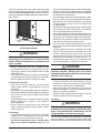
Horizontal to Downfl ow Conversion
The unit is shipped ready for horizontal duct connections.
If down fl ow ducts are required, the unit must be converted
following the steps below for the supply and return ducts.
1. Locate the duct cap inside the duct openings and
remove the screw holding it in place.
2 Lift the cap out of the unit. (Hint: The cap can be
pushed up from the bottom by reaching through the
fork slot).
3. Cover the horizontal duct opening with the horizontal
duct cap. The insulation will be on the indoor side.
4. Fasten the cover with screws to seal.

9
Condensate
Drain
Figure 6. Condensate Drain Location
same size and prime with water. When connecting rigid
drain line, hold the female fi tting with a wrench to prevent
twisting. Do not over tighten! Refer to local codes and
restrictions for proper condensate disposal requirements.
See Figure 6.
switch shall be capable of electrically de-energizing the
outdoor unit. See unit data label for proper incoming fi eld
wiring. Any other wiring methods must be acceptable
to authority having jurisdiction.
• Use only copper wire for the line voltage power supply
to this unit (Table 2, page 10). Use proper code agency
listed conduit and a conduit connector for connecting
the supply wires to the unit. Use of rain tight conduit
is recommended.
• See the unit wiring label for proper high and low voltage
wiring. Make all electrical connections in accordance
with all applicable codes and ordinances.
• Overcurrent protection must be provided at the branch
circuit distribution panel and sized as shown on the unit
rating label and according to applicable local codes.
See the unit rating plate for maximum circuit ampacity
and maximum overcurrent protection limits.
• Check all factory wiring to the wiring diagrams. Verify
none of the connections loosened during shipping or
installation.
• A wiring diagram/schematic is located on the inside
cover of the electrical box of the outdoor unit. The
installer should become familiar with the wiring
diagram/schematic before making any electrical
connections to the outdoor unit. See Figures 12 - 17.
• Provide power supply for the unit in accordance with
the unit wiring diagram, and the unit rating plate.
CAUTION:
Label all wires prior to disconnection when
servicing controls. Wiring errors can cause
improper and dangerous operation. Verify proper
operation after servicing.
• Units are shipped from the factory wired for 240 volt
transformer operation. For 208V operation, remove
the lead from the transformer terminal marked 240V
and connect it to the terminal marked 208V.
• Internally mounted circuit breakers are available as
fi eld installed options. These circuit breakers can be
used as an electrical disconnect.
• Connect the line-voltage leads to the terminals on the
contactor inside the control compartment.
Grounding
WARNING:
The unit cabinet must have an uninterrupted or
unbroken electrical ground to minimize personal
injury if an electrical fault should occur. Do not
use gas piping as an electrical ground
!
This unit must be electrically grounded in accordance
with local codes or, in the absence of local codes, with
the National Electrical Code (ANSI/NFPA 70) or the CSA
ELECTRICAL WIRING
WARNING:
Shut off all electrical power to the unit before
performing any maintenance or service on the
system. Failure to comply may result in personal
injury or death.
• Electrical connections must be in compliance with
all applicable local codes and ordinances, and with
the current revision of the National Electric Code
(ANSI/NFPA 70).
• For Canadian installations, the electrical connections
and grounding shall comply with the current Canadian
Electrical Code (CSA C22.1 and/or local codes).
Pre-Electrical Checklist:
Verify that the voltage, frequency, and phase of the
supply source match the specifi cations on the unit
rating plate.
Verify that the service provided by the utility is suffi cient
to handle the additional load imposed by this equipment.
refer to the unit wiring label for proper high and low
voltage wiring.
Verify factory wiring is in accordance with the unit wiring
diagram (Figures 12 - 17, pages 17 - 22). Inspect for
loose connections.
Phase balance on 3 phase units must always be
checked. See Unbalanced 3-Phase Supply Voltage
section (page 10).
Line Voltage
• It is recommended that the line voltage to the unit be
supplied from a dedicated branch circuit containing
the correct fuse or circuit breaker for the unit.
• An electrical disconnect must be located within
sight of and readily accessible to the unit. This

10
C22.1 Electrical Code. Use the grounding lug provided
in the control box for grounding the unit.
Thermostat Connections
Several thermostat options are available depending on the
accessories installed with the unit. See Figure 10 (page
15) for 208/230V units or Figure 11 (page 16) for 460V
units. Select a thermostat that operates in conjunction with
the installed accessories. The low voltage wires must be
properly connected to the units low voltage terminal block.
Recommended wire gauge and wire lengths for typical
thermostat connections are listed in Table 3.
IMPORTANT NOTE: The thermostat should be
mounted about 5 feet above the fl oor on an inside
wall. DO NOT install the thermostat on an outside
wall or any other location where its operation may
be adversely affected by radiant heat from fi replaces,
sunlight, or lighting fi xtures, and convective heat from
warm air registers or electrical appliances. Refer to
the thermostat manufacturer’s instruction sheet for
detailed mounting and installation information.
Table 3. Thermostat Wire Gauge
Thermostat
Wire Gauge
Recommended T-Stat Wire
Length (Unit to T-Stat)
2-Wire
(Heating)
5-Wire
(Heating/Cooling)
24 55 25
22 90 45
20 140 70
18 225 110
Blower Speed
CAUTION:
To avoid personal injury or property damage,
make certain that the motor leads cannot
come into contact with any uninsulated metal
components of the unit.
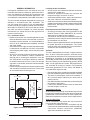
Example:
AB = 451V
BC = 460V
AC = 453V
2. Determine the average voltage in the power supply.
3. Determine the maximum deviation:
4. Determine percent of
voltage imbalance by
using the results from
steps 2 & 3 in the
following equation.
max voltage deviation
from average voltage
=100x
average voltage
% Voltage Imbalance
6
454
100
x
= 1.32%
Example:
1. Measure the line
v o l t a g e s o f y o u r 3 p h a s e
power supply where it
enters the building and
at a location that will
only be dedicated to the
unit installation (at the
units circuit protection
or disconnect).
Unbalanced 3-Phase Supply Voltage
Voltage unbalance occurs when the voltages of all phases
of a 3-phase power supply are no longer equal. This
unbalance reduces motor effi ciency and performance.
Some underlying causes of voltage unbalance may
include: Lack of symmetry in transmission lines, large
single-phase loads, and unbalanced or overloaded
transformers. A motor should never be operated when a
phase imbalance in supply is greater than 2%.
Perform the following steps to determine the percentage
of voltage imbalance:
In this example, the measured line voltages were
451, 460, and 453. The average would be 454 volts
(451 + 460 + 453 = 1,364 / 3 = 454).
The amount of phase imbalance (1.32%) is satisfactory
since the amount is lower than the maximum allowable
2%. Please contact your local electric utility company if
your voltage imbalance is more than 2%.
Example:
From the values given in step 1, the BC voltage
(460V) is the greatest difference in value from
the average:
460 - 454 = 6
454 - 451 = 3
454 - 453 = 1
Highest Value
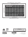
COPPER WIRE SIZE — AWG
(1% Voltage Drop)
Supply Wire Length-Feet
Supply Circuit
Ampacity
200 150 100 50
6 8 10 14 15
46812 20
46810 25
44610 30
3468 35
3468 40
2346 45
2346 50
2346 55
1234 60
Wire Size based on N.E.C. for 60° type copper conductors.
Table 2. Copper Wire Size

11
The blower speed for 3 and 4 ton units is preset at the
factory for operation at the same speed for heating and
cooling. These factory settings are listed in Table 5
(page 16).For optimum system performance and comfort,
it may be necessary to change the factory set speed.
PSC Motor - 208/230V
1. Shut off all electrical power to the unit and remove
the service panel.
2. Remove the motor lead from terminal #4 of the blower
relay. Cut the wire tie from the lead bundle. The
motor leads are color coded as shown in Figure 7.
3. If the desired heating blower speed is different than
the cooling speed, remove and discard the jumper
wire between terminals #6 & #4 on the blower relay.
Place the desired heating blower speed lead on
terminal #6 and the desired cooling blower speed
lead on terminal #4 of the blower relay. Bundle the
remaining motor leads together with a fi eld supplied
wire tie.
PIN NUMBER
MOTOR SPEED
WIRE COLOR
1
LOW
RED
2
4
HIGH
BLACK
3
MEDIUM
BLUE
5
N/A
N/A
6
COMMON
WHITE
1
2
4
3
5
6
RED
BLACK
BLUE
WHITE
Figure 7. Motor Lead Connector -
PSC Motor - 208/230V
PIN NUMBER
MOTOR SPEED
WIRE COLOR
1
LOW
RED
FOR LOW SPEEDS*
ORANGE
2
4
HIGH
BLACK
3
MEDIUM
BLUE
5
N/A
N/A
6
COMMON
WHITE
1
2
4
3
5
6
RED
BLACK
BLUE
ORANGE
WHITE
Figure 8. Motor Lead Connector -
PSC Motor - 460V
PSC Motor - 460V
NOTE: Unit is preset for low speed (red wire).
1. Shut off all electrical power to the unit and remove
the service panel.
2. Low speed: Connect the black and orange wires
together via the terminal block.
Medium speed: Remove the red wire from terminal
3 on the relay and replace it with the blue wire. Motor
leads are code Q in Figure 8.
High speed: Connect the black wire to terminal 3
on the relay. Tie off the orange, red, and blue wires.
They are not connected for high speed.
Fixed Torque ECM Motor
1. Shut off all electrical power to the unit and remove
the blower panel. Locate the orange and red wires
terminated to the blower motor. NOTE: The orange
wire controls cooling operation while the red wire
controls heating operation.
2. Verify the required speed from the airfl ow data found
in Table 5. Place appropriate wire on the correct motor
speed tap for the required airfl ow point.
Optional Outdoor Thermostat
An outdoor thermostat can be installed in the fi eld with
2-stage electric heat. To install the outdoor thermostat,
remove the orange wire from the E terminal on the terminal
block, and connect to the outdoor thermostat. Connect
the other side of the outdoor thermostat to W2 from the
thermostat.
Optional Electric Heater Kits
This packaged air conditioner is designed to allow optional
electric heat to be fi eld installed as required by the
building’s particular heating load. The options available
for each unit are shown in the heater kit installation
instructions.
Optional fi eld-installed electric heater kits are available
in 5 kw to 20 kw heating capacities for single phase, and
9 kw to 15 kw heating capacities for three phase. A separate
installation instruction document for the electric heaters
and their application is shipped with the heater kits.
A single stage 24VAC thermostat should be used with
these units. If electric heat is installed, a single-stage or
two- stage heating thermostat will be required depending
on the heater kit. Install the heater kits as directed by the
instructions supplied with the heater kit. Follow all cautions
and warnings as directed.

12
START UP & SYSTEM CHECK
Pre-Start Check List
Verify the unit is level and allows condensate to drain.
Verify the outdoor coil and top of the unit are free from
obstructions and debris, and all equipment access/
control panels are in place.
Verify that the duct work is sealed to prevent air leakage.
Verify that the line voltage power leads are securely
connected and the unit is properly grounded.
Verify that the low voltage wires are securely connected
to the correct leads on the low voltage terminal strip.
Verify that the outdoor fan turns freely.
Verify that the power supply branch circuit overcurrent
protection is sized properly.
Verify that the thermostat is wired correctly. The
thermostat system mode should be set to OFF and
the thermostat fan mode should be set to AUTO.
Start-Up Procedure
Close all electrical disconnects to energize the system.
Air Circulation
Leave the thermostat system mode on OFF, and set the
fan mode to ON. Blower should run continuously. Check
the air delivery at the supply registers and adjust register
openings for balanced air distribution. Examine ductwork
for leaks or obstruction if insuffi cient air is detected. Set
the thermostat fan mode to AUTO. The blower should
stop running.
WARNING:
If the unit is equipped with a crankcase heater,
allow 24 hours prior to continuing the start up
procedures to allow for heating of the refrigerant
compressor crankcase. Failure to comply may
result in damage and could cause premature
failure of the system. This warning should be
followed at initial start up and any time the power
has been removed for 12 hours or longer.
System Cooling
1. Set the thermostat’s system mode to COOL and the
fan mode to AUTO. Gradually lower the thermostats
setpoint below room temperature and verify the outdoor
unit and indoor blower energize.
2. Feel the air being circulated by the indoor blower
and verify that it is cooler than ambient temperature.
Listen for any unusual noises. If unusual sounds
occur, determine the source of the noise and correct
as necessary.
3. Allow the cooling system to operate for several minutes
and then set the temperature selector above room
temperature. Verify the fan and compressor cycle off
with the thermostat. NOTE: The blower should also
stop unless fan mode is set to ON.
Refrigerant Charging
WARNING:
Single Packaged Air Conditioners are shipped
fully charged with R-410A refrigerant and ready
for installation. When a system is installed
according to these instructions, no refrigerant
charging is required. If repairs make it necessary
for evacuation and charging, it should only be
done by qualifi ed, trained personnel thoroughly
familiar with this equipment. Some local codes
require licensed installation/service personnel
to service this type of equipment. Under no
circumstances should the owner attempt to
install and/or service this equipment. Failure to
comply with this warning could result in property
damage, personal injury, or death.
The system refrigerant charge can be checked and
adjusted through the service ports provided at the front
panel. Use only gauge lines which have a Schrader
depression device present to actuate the valve.
NOTES:
• To achieve rated capacity and effi ciency the compressor
must be exposed to refrigerant for at least 24 hours
prior to running and then must be run for a minimum
of 12 hours.
• The refrigerant charging charts (Figures 18 - 20,
pages 23 & 24) are applicable to listed assemblies
of equipment and at listed airfl ows for the indoor coil.
Assemblies of indoor coils and outdoor units not listed
are not recommended.
Charging an R-410A Unit in AC Mode at Outdoor
Temperatures Above 65F.
1. With the system operating at steady-state, measure
the liquid refrigerant pressure in psig at the service
valve.
2. Measure the liquid refrigerant temperature in
Fahrenheit at the service valve.
3. For the temperature measured, determine the required
liquid refrigerant pressure from the appropriate
charging charts in Figures 18 - 20.
4. If the pressure measured in step 1 is greater than
the required liquid refrigerant pressure determined in
System Heating
If t he unit has been e qu ip ped wi th optional ele ctr ic heater
kits, set the thermostat's system mode to HEAT and the
fan mode to AUTO. Verify the compressor and outdoor
fan are not energized but that the blower and heaters are.
Feel the air being circulated by the indoor blower and verify
that it is warmer than ambient temperature. Listen for any
unusual noises. If unusual sounds occur, determine the
source of the noise and correct as necessary.

13
AIR CONDITIONER MAINTENANCE
WARNING:
To prevent electrical shock, personal injury, or
death, disconnect all electrical power to the unit
before performing any maintenance or service.
The unit may have more than one electrical
supply.
Proper maintenance is important to achieve optimum
performance from the Air Conditioner. The ability to
properly perform maintenance on this equipment requires
certain mechanical skills and tools. If you do not possess
these skills, contact your dealer for maintenance. Consult
your local dealer about the availability of maintenance
contracts. Routine maintenance should include the
following:
• Inspect the condensate drain and outdoor coil at the
beginning of each cooling season. Remove any debris.
Clean the outdoor coil and louvers as necessary using
a mild detergent and water. Rinse thoroughly with
water.
• Inspect the electrical connections for tightness at the
beginning of each heating and cooling season. Service
as necessary.
• Inspect and clean or replace air fi lters at the beginning
of each heating and cooling season, or more frequently
if required.
CAUTION:
The unit should never be operated without a
fi lter in the return air system. Replace disposable
fi lters with the same type and size.
• The motors for the circulating air blower and the outdoor
fan are pre-lubricated at the factory. No further oiling
is required for the life of this product.
step 4, then there is too much charge in the system.
Remove refrigerant and repeat steps 1 through 3 until
the system is correctly charged.
5. If the pressure measured in step 1 is less than the
required liquid refrigerant pressure determined in step
4, then there is too little charge in the system. Add
refrigerant and repeat steps 1 - 3 until the system is
correctly charged.

14
Top View
24 9/10
13 1/2
16
12
13 3/10
13 1/2
16
12
CG
A
47 1/2
3/4" NPT Female
Drain Connector
B
DOWNFLOW
SUPPLY DUCT
OPENING
DOWNFLOW
RETURN DUCT
OPENING
23 1/2
Back View
13.5
16.0
13.7
13.5
16.0
12.45
11.75 22.75
55.8
C
HORIZONTAL
SUPPLY DUCT
OPENING HORIZONTAL
RETURN DUCT
OPENING
4.0
CONDENSING
COIL
5.0
8
4.00
Table 4. Center of Gravity & Unit Shipping Weights
Model Number
P6SD -
Unit
Weight
Center of Gravity Height -C-
(in inches)
-A- -B-
with base rails without base rails
X36 405 29.5 26.0 39.0 35.3
X48 415 29.5 26.5 39.0 35.3
X60 480 30.0 27.5 43.0 39.3
Side View
1 1/4 Ø Power Entry
1 3/4 Ø Power Entry (Capped)
22/25 Ø Control Wiring Entry
23 3/5
27 1/5
30
1 4/5
4
Figure 9. P6SD Air Conditioner Dimensions
FIGURES & TABLES

15
ELECTRICAL INFORMATION
R
Y
C
G
W
1
2
3
4
5
6
7
8
9
Gray
Yellow
Blue
ECONOMIZER
PLUG
INDOOR
THERMOSTAT
SUB-BASE
Red
Black
Green
FROM
TRANSFORMER
FROM
CONTACTOR
FROM
BLOWER RELAY
(Optional,
Check
Thermostat
Instructions)
1
2
3
4
5
6
7
8
9
Brown
Orange
ACCESSORY
HEAT PLUG
Typical Wiring (Field Supplied) for 1-Stage Cool, 1-Stage Heat
R
Y1
Y2
C
G
1
2
3
4
5
6
7
8
9
Gray
Yellow
Blue
ECONOMIZER
PLUG
INDOOR
THERMOSTAT
SUB-BASE
Red
Black
Green
FROM
TRANSFORMER
FROM
CONTACTOR
FROM
BLOWER RELAY
(Optional, Check
Thermostat Instructions)
1
2
3
4
5
6
7
8
9
Brown
Orange
ACCESSORY
HEAT PLUG
W1
W2
Optional
Outdoor Thermostat
(Field Supplied)
Typical Wiring (Field Supplied) for 2-Stage Cool, 2-Stage Heat with an Optional Outdoor Thermostat
Figure 10. Typical Air Conditioner Thermostat Connections - 208/230V

16
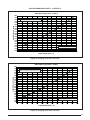
Model Number
P6SD -
External Static Pressure Drop - inches water column
0.1 0.2 0.3 0.4 0.5 0.6 0.7 0.8
X36
High 1610 1562 1504 1442 1365 1295 1214 1109
Medium 1367 1320 1271 1205 1138 1065 968 845
Low* 1153 1102 1043 990 912 831 731 618
X48
High 2361 2278 2218 2141 2066 1976 1870 1758
Medium 2026 1982 1935 1889 1822 1744 1660 1554
Low* 1584 1568 1532 1489 1445 1387 1322 1236
X60
Tap T1 1515 1450 1380 1350 1280 1250 1200 1160
Tap T2** 1580 1520 1460 1400 1300 1280 1260 1230
Tap T3* 1740 1690 1650 1600 1360 1500 1460 1390
Tap T4 1960 1910 1840 1820 1540 1740 1700 1600
Tap T5 2090 2050 2010 1975 1780 1900 1850 1790
NOTES:
Airfl ow performance is with a dry coil
* Denotes factory set cooling speed
** Denotes factory set electric heating speed
Table 5. P6 Series Packaged Air Conditioner Blower Curves
R
Y2
Y
C
G
W
1
2
3
4
5
6
7
8
9
Gray
Yellow
Blue
ECONOMIZER
PLUG
INDOOR
THERMOSTAT
SUB-BASE
Red
Black
Green
FROM
TRANSFORMER
FROM
CONTACTOR
FROM
BLOWER RELAY
(Optional,
Check
Thermostat
Instructions)
1
2
3
4
5
6
7
8
9
10
11
12
Brown
Orange
24V Common
ACCESSORY
HEAT PLUG
Figure 11. Typical Air Conditioner Thermostat Connections - 460V

17
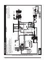
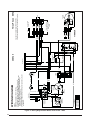
Figure 12. Wiring Diagram-PSC Motor, Three Phase
WIRING DIAGRAM
NOTES:
7110110
1109
FIELD WIRING
LEGEND:
LOW VOLTAGE
HIGH VOLTAGE
208/230 Volt zH06 esahP eerhTrenoit
idnoC riA degakcaP elbatre
vnoC
1. Disconnect all power before servicing.
2. For supply connections use copper conductors only.
3. Not suitable on systems that exceed 150 V to ground.
4. If any of the original wire as supplied with the furnace must be
replaced, it must be replaced with wiring material having a
temprature rating of at least 105°C.
1. Couper le courant avant de faire letretien.
2. Employez uniquement des conducteurs en cuivre.
3. Ne convient pas aux installations de plus de
150 V la terre.
5. For supply wire ampacities and overcurrent protection, see unit
rating plate.
¢711011S¤
1
2
3
4
5
6
7
8
9
R
C
S
1
5
2
6
3
4
TO 208/230 VAC
POWER SUPPLY
9
8
1
7
6
5
4
3
2
9
8
1
7
6
5
4
3
2
9
8
1
7
6
5
4
3
2
9
8
1
7
6
5
4
3
2
COMPRESSOR
COMPRESSOR
CONTACTOR
CAPACITOR
PLUG
A
OUTDOOR
FAN MOTOR
PRESSURE
SWITCH
TO DISCHARGE
AIR SENSOR
3 AMP
FUSE
T2
T1
N
G
L
C
T3
T4
T5
BLOWER
MOTOR
TRANSFORMER
T3
T2
T1
CCH
L1
L2L3
T1T2T3
24V
240V
208V
COM
GC
W1Y2Y1 R
ORANGE
BLACK
BLACK
BLACK
YELLOW
BLACK
BLUE
YELLOW
RED
RED
RED
RED
ORANGE
BLUE
BLUE
YELLOW
YELLOW
YELLOW
YELLOW
ORANGE
BLACK
BLACK
GREY
GREY
GREEN
BLACK
ORANGE
GREEN
GREEN
GREEN
GREEN/GREY
RED
RED
RED
RED
RED
BROWN
RED
BLACK
BLUE
WHITE
BLACK
WHITE
YELLOW
YELLOW
BK
BK
BK

18
208/230 Volt zH06 esahP eerhTrenoitidnoC riA degakca
P
e
lb
at
revnoC
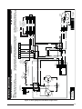
WIRING DIAGRAM
NOTES:
1. Disconnect all power before servicing.
2. For supply connections use copper conductors only.
3. Not suitable on systems that exceed 150 V to ground.
4. If any of the original wire as supplied with the furnace must be
replaced, it must be replaced with wiring material having a
temprature rating of at least 105°C.
5. For supply wire ampacities and overcurrent protection, see unit
rating plate.
1. Couper le courant avant de faire letretien.
2. Employez uniquement des conducteurs en cuivre.
3. Ne convient pas aux installations de plus de
150 V la terre.
7110100
1109
FIELD WIRING
LEGEND:
LOW VOLTAGE
HIGH VOLTAGE
¢711010M¤
1
2
3
4
5
6
7
8
9
1
2
3
4
5
6
7
8
9
R
C
S
1
5
2
6
3
4
TO 208/230 VAC
POWER SUPPLY
9
8
1
7
6
5
4
3
2
9
8
1
7
6
5
4
3
2
9
8
1
7
6
5
4
3
2
9
8
1
7
6
5
4
3
2
COMPRESSOR
COMPRESSOR
CONTACTOR
T3
T2
T1
CAPACITOR
PLUG
A
OUTDOOR
FAN MOTOR
PRESSURE
SWITCH
TO DISCHARGE
AIR SENSOR
3 AMP
FUSE
TRANSFORMER
L
C
M
H
1
2
3
4
5
6
1
2
3
4
5
6
CCH
L1L2
L3
T1T2T3
BLOWER
MOTOR
BLOWER
RELAY
24V
240V
208V
COM
GC
W1Y2Y1 R
BLACK
BLACK
BLACK
ORANGE
BLACK
BLUE
RED
BLUE
BLACK
WHITE
BROWN
YELLOW
YELLOW
YELLOW
BLACK
BLACK
BLACK
BLACK
WHITE
WHITE
RED
WHITE
WHITE
GREY
GREEN
GREEN
GREY
GREEN
YELLOW
YELLOW
BLUE
BLUE
BLUE
BLUE
RED
RED
RED
RED
RED
RED
RED
RED
RED
RED
ORANGE
ORANGE
ORANGE
ORANGE
BLACK
BLACK
BLACK
BROWN
YELLOW
YELLOW
BLACK
BLACK
BK
Figure 13. Wiring Diagram-Fixed Torque Motor, Three Phase

19
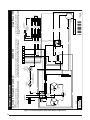
Figure 14. Wiring Diagram-PSC Motor, Single Phase
208/230 VoltConvertible Packaged Air Conditioner Single Phase / 60Hz
WIRING DIAGRAM
NOTES:
1. Disconnect all power before servicing.
2. For supply connections use copper conductors only.
3. Not suitable on systems that exceed 150V to ground.
4. If any of the original wire as supplied with the furnace must be replaced, it must
be replaced with wiring material having a temperature rating of at least 105°C.
5. For supply wire ampacities and overcurrent protection, see unit rating plate.
1. Couper le courant avant de faire letretien.
2. Employez uniquement des conducteurs en cuivre.
3. Ne convient pas aux installations de plus de 150V
a la terre.
7110330
1209
FIELD WIRING
LEGEND:
LOW VOLTAGE
HIGH VOLTAGE
L
C
M
H
1
2
3
4
5
6
1
2
3
4
5
6
7
8
9
1
2
3
4
5
6
7
8
9
1
2
3
4
5
6
BLOWER
PLUG
BLOWER
MOTOR
5
4
3
2
1
9
8
7
6
5
4
3
2
1
9
8
7
6
5
4
3
2
1
9
8
7
6
5
4
3
2
1
9
8
7
6
3 AMP
FUSE
CCH
BLACK
13
65
24
T2 T1
L2 L1
S
R
C
S
R
C
YELLOW
BLACK
BLUE
RED
ORANGE
TO DISCHARGE
AIR SENSOR
ECONOMIZER JUMPER
HARNESS ASSY
8-WIRE
ECONOMIZER PLUG
COPMPRESSOR
DUAL
CAPACITOR
TO 208/230 VAC
POWER SUPPLY
OUTDOOR
FAN MOTOR
HEATER
PLUG
COMPRESSOR
CONTACTOR
(IF EQUIPPED)
HIGH
PRESSURE
SWITCH
RED
WHITE
BLUE
BLACK
BROWN
NOTE: ONLY REQUIRED IF
NO LOW PRESSURE SWITCH
YELLOW
YELLOW
WHITE
24V
208V
COM
240V
Y1W1
RCG Y2
LOW
PRESSURE
SWITCH
(ON SELECT
MODELS ONLY)
YELLOW
WHITE
YELLOW
BLACK
BLACK
BLACK
RED
RED
BLUE
ORANGE
WHITE
BROWN
ORANGE
BLACK
GREEN
RED
RED
RED
RED
BLACK
BLUE
YELLOW
ORANGE
BLUE
YELLOW
BLACK
GRAY
GREEN
BLUE
YELLOW
BLACK
GRAY
GREEN
RED
RED
YELLOW
RED
YELLOW
YELLOW
RED
RED
WHITE

20
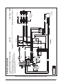
WIRING DIAGRAM
NOTES:
7110340
1209
FIELD WIRING
LEGEND:
LOW VOLTAGE
HIGH VOLTAGE
208/230 Volt zH06 / esahP elgniSrenoitidnoC riA degakcaP elbitrevnoC
1. Disconnect all power before servicing.
2. For supply connections use copper conductors only.
3. Not suitable on systems that exceed 150V to ground.
4. If any of the original wire as supplied with the furnace must be replaced, it must
be replaced with wiring material having a temperature rating of at least 105°C.
5. For supply wire ampacities and overcurrent protection, see unit rating plate.
1. Couper le courant avant de faire letretien.
2. Employez uniquement des conducteurs en cuivre.
3. Ne convient pas aux installations de plus de 150V
a la terre.
¢711034o¤
1
2
3
4
5
6
7
8
9
5
4
3
2
1
9
8
7
6
5
4
3
2
1
9
8
7
6
5
4
3
2
1
9
8
7
6
5
4
3
2
1
9
8
7
6
3 AMP
FUSE
CCH
COMPRESSOR
OUTDOOR
FAN MOTOR
HEATER
PLUG
BLOWER
RELAY
DUAL
CAPACITOR
S
R
C
L2 L1
T2 T1
S
R
C
BLUE
ORANGE
T2
T1
N
G
L
C
T3
T4
T5
BLOWER
MOTOR
NOTE: FOR BLOWER MOTOR WIRING
SEE #XL0132
ECONOMIZER PLUG
ECONOMIZER JUMPER
HARNESS ASSY
8-WIRE
TO DISCHARGE
AIR SENSOR
YELLOW
YELLOW
YELLOW
HIGH
PRESSURE
SWITCH
TO 208/230 VAC
POWER SUPPLY
BLACK
NOTE: ONLY REQUIRED IF
NO LOW PRESSURE SWITCH
1
4
2
6
5
3
YELLOW
RED
BLACK
Y1W1
RCG Y2
LOW
PRESSURE
SWITCH
(ON SELECT
MODELS ONLY)
24V
208V
COM
240V
RED
BLACK
BLACK
BLACK
RED
ORANGE
BROWN
YELLOW
YELLOW
WHITE
ORANGE
BLUE
YELLOW
BLACK
RED
RED
RED
RED
GREEN
GRAY
BLUE
YELLOW
BLACK
GRAY
GREEN
RED
BLACK
ORANGE
GN/YE STRIPE
BLUE
WHITE
RED
GREEN
YELLOW
YELLOW
BLACK
RED
YELLOW
RED
Figure 15. Wiring Diagram-Fixed Torque Motor, Single Phase
Page is loading ...
Page is loading ...
Page is loading ...
Page is loading ...
-
 1
1
-
 2
2
-
 3
3
-
 4
4
-
 5
5
-
 6
6
-
 7
7
-
 8
8
-
 9
9
-
 10
10
-
 11
11
-
 12
12
-
 13
13
-
 14
14
-
 15
15
-
 16
16
-
 17
17
-
 18
18
-
 19
19
-
 20
20
-
 21
21
-
 22
22
-
 23
23
-
 24
24


Unbranded GP6SD Installation guide
- Type
- Installation guide
- This manual is also suitable for
Ask a question and I''ll find the answer in the document
Finding information in a document is now easier with AI
Related papers
Other documents
-
Intertherm S5BXM Installation guide
-
Carrier 50ZP060300 Owner's manual
-
Avanti BCC113Q0W Instructions Manual
-
Heat Controller RSG1424S1E Owner's manual
-
Reznor JS4BD User manual
-
Payne 116B Owner's manual
-
Mammoth R8GE, Single Phase Installation guide
-
Reznor R6GD Installation guide
-
Broan Q6SD-X Installation guide
-
Reznor R8HE Series Installation guide