Page is loading ...

MITSUBISHI
THE BIG SCREEN COMPANY _"

RISK OF ELECTRIC SHOCK
DO NOT OPEN
CAUTION: TO REDUCE THE RISK OF ELECTRIC SHOCK, DO NOT REMOVE
COVER (OR BACK).
NO USER SERVICEABLE PARTS INSIDE.
REFER SERVICING TO QUALIFIED SERVICE PERSONNEL.
The lightning flash with arrowhead symbol within an equilateral triangle is intended to alert the
user of the presence of uninsulated "dangerous voltage" within the product's enclosure that
may be sufficient magnitude to constitute a risk of electric shock.
The exclamation point within an equilateral triangle is intended to alert the user to the
presence of important operating and maintenance (servicing) instructions in the literature
panying the appliance.
Warning: To avoid permanently imprinting a fixed image onto your TV screen, please do not display the
same stationary images on the screen for more that 15% of your total TV viewing in one week. Examples
of stationary images are letterbox top/bottom bars from DVD disc or other video sources, side bars when
showing standard TV pictures on widescreen TVs, stock market reports, video game patterns, station
Iogos, web sites or stationary computer images. Such patterns can unevenly age the picture tubes causing
permanent damage to the TV. Please see pages 25 and 70 for a detailed explanation.
Note: This equipment has been tested and found to comply with the limits for a Class B digital device,
pursuant to part 15 of the FCC Rules. These limits are designed to provide reasonable protection
against harmful interference in a residential installation. This equipment generates, uses and can radiate
radio frequency energy and, if not installed and used in accordance with the instructions, may cause
harmful interference to radio communications. However, there is no guarantee that interference will not
occur in a particular installation. If this equipment does cause harmful interference to radio or television
reception, which can be determined by turning the equipment off and on, the user is encouraged to try
to correct the interference by one or more of the following measures:
• Reorient or relocate the receiving antenna.
• Increase the separation between the equipment and the receiver.
• Connect the equipment into an outlet on a circuit different from that to which the receiver is
connected.
• Consult the dealer or an experienced radio/TV technician for help.
Changes or modifications not expressly approved by Mitsubishi could void the user's authority to operate
this equipment.
WARNING:
TO REDUCE THE RISK OF FIRE OR ELECTRIC SHOCK, DO NOT EXPOSE THIS APPLIANCE TO RAIN
OR MOISTURE.
CAUTION:
TO PREVENT ELECTRIC SHOCK, MATCH WIDE BLADE OF PLUG TO WIDE SLOT, FULLY INSERT.
NOTE TO CATV SYSTEM INSTALLER:
THIS REMINDER IS PROVIDED TO CALL THE CATV SYSTEM INSTALLER'S ATTENTION TO ARTICLE
820-40 OF THE NEC THAT PROVIDES GUIDELINES FOR THE PROPER GROUNDING AND, IN PAR-
TICULAR, SPECIFIES THAT THE CABLE GROUND SHALL BE CONNECTED TO THE GROUNDING
SYSTEM OF THE BUILDING, AS CLOSE TO THE POINT OF CABLE ENTRY AS PRACTICAL.

Table of Contents
IMPORTANT SAFEGUARDS ............................................................................ 4-5
S,ppendix A: Bypassing the V-Chip Lock ........................................................................................................... 71
S,ppendix B: Input Connection Compatibility .................................................................................................... 73
S,ppendix C: Remote Control Programing Codes ............................................................................................. 74
S,ppendix D: Cleaning and Service ................................................................................................................ 75-76
S,ppendix E: Diamond Shield Instructions .................................................................................................... 77-78
S,ppendix F: Cabinet Separation ................................................................................................................... 79-80
S,ppendix G: Troubleshooting ........................................................................................................................ 81-82
ndex ................................................................................................................................................................. 83-84
Vlitsubishi Projection TV Limited Warranty ....................................................................................................... 85

IMPORTANT SAFEGUARDS
Please read the following safeguards for your TV and retain for future reference.
__Always follow all warnings and instructions marked on the television.
=
=
=
=
=
Read, Retain and Follow All Instructions
Read all safety and operating instructions before operating the TV. Retain the safety and operating instructions
for future reference. Follow all operating and use instructions.
Heed Warnings
Adhere to all warnings on the appliance and in the operating instructions.
Cleaning
Unplug the TV from the wall outlet before cleaning. Do not use liquid, abrasive, or aerosol cleaners. Cleaners
can permanently damage the cabinet and screen. Use a lightly dampened cloth for cleaning.
Attachments and Equipment
Never add any attachments and/or equipment without approval of the manufacturer as such additions may
result in the risk of r_ d ect ricshock or ct I_r personal i_ ury.
Water and Moisture
Do not use the TV where contact with or immersion in water is possible. Do not use near bath tubs, wash
bowls, kitchen sinks, laundry tubs, swimming pools, etc.
6. Accessories
=
Do not place the TV on an unstable cart, stand, tripod, or table. The TV may fall, causing
serious injury to a child or adult and serious damage to the TV. Use only with a cart, stand,
tripod, bracket, or table recommended by the manufacturer, or sold with the TV. Any mounting
of the TV should follow the manufacturer's instructions, and should use mounting accessories
recommended by the manufacturer.
An appliance and cart combination should be moved with care. Quick stops, excessive force,
and uneven surfaces may cause the appliance and cart combination to overturn.
Ventilation
Slots and openings in the cabinet are provided for ventilation and to ensure reliable operation of the TV and
to protect it from overheating. Do not block these openings or allow them to be obstructed by placing the TV
on a bed, sofa, rug, or other similar surface. Nor should it be placed over a radiator or heat register. If the
TV is to be placed in a rack or bookcase, ensure that there is adequate ventilation and that the manufacturer's
instructions have been adhered to.
=
g=
10.
11.
Power Source
This TV should be operated only from the type of power source indicated on the marking label. If you are not
sure of the type of power supplied to your home, consult your appliance dealer or local power company.
Grounding or Polarization
This TV is equipped with a polarized alternating current line plug having one blade wider than the other. This
plug will t irt ot 1_power cut le ml yone vvay. If y_uar eunabl et oi rser t tl_ pl _ f d lyi rtot I_ out le, try
reversing the plug. If the plug should still fail to t, eont a;t _our d a:t d(_ant or epl aneyour cbsol e eout le. I_
not defeat the safety purpose of the polarized plug.
Power-Cord Protection
Power-supply cords should be routed so that they are not likely to be walked on or pinched by items placed
upon or against them, paying particular attention to cords at plugs, convenience receptacles, and the point
where they exit from the TV.
Lightning
For added protection for this TV during a lightning storm, or when it is left unattended and unused for long
periods of time, unplug it from the wall outlet and disconnect the antenna or cable system. This will prevent
damage to the TV due to lightning and power-line surges.

IMPORTANT SAFEGUARDS Continued
12.
13.
14.
15.
16.
17.
18.
19.
20.
Power Lines
An outside antenna system should not be located in the vicinity of overhead power lines or other electric light
or power circuits, or where it can fall into such power lines or circuits. When installing an outside antenna
system, extreme care should be taken to keep from touching such power lines or circuits as contact with
them might be fatal.
Overloading
Do not overload wall outlets and extension cords as this can result in a risk of reor el e:t ricshock.
Object and Liquid Entry
Never push objects of any kind into this TV through openings as they may touch dangerous voltage points or
short-out parts that could result in reor el e:t ricshock. I_ ver spi II li_i dof any ki _ on or irtot haTV.
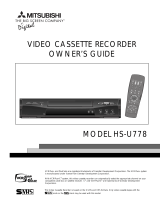
Outdoor Antenna Grounding
If an outside antenna or cable system is connected to the TV, be
sure the antenna or cable system is grounded so as to provide
some protection against voltage surges and built-up static charges.
Section 810 of the National Electric Code, ANSI/NFPA No.
70-1984, provides information with respect to proper grounding of
the mast and supporting structure, grounding of the lead in wire to
an antenna discharge unit, size of grounding conductors, location
of antenna discharge unit, connection to grounding electrodes, and
requirements for the grounding electrode.
Servicing
EXAMPLE OF ANTENNA GROUNDING
/ OUNDC MP._
UNIT
I <NEDSEOT,ONO,O-=O>
I EQUIPMENT_I-- / /"---J GROUNDING
_---.4_[_./_Y'_ CONDUCTORS
__;_'_R(oNuECDS_ _T_Ns 810-21 )
"_'_"_POWER SERVICE GROUNDING
ELECTRODE SYSTEM
NEC -- NATIONAL ELECTRICAL CODE (NEC ART 250 PART H/
Do not attempt to service this TV yourself as opening or removing covers may expose you to dangerous
voltage or other hazards. Refer all servicing to quali edser vi_ per sonnel.
Damage Requiring Service
Unplug the TV from the wall outlet and refer servicing to quali edser vi _ per sonnel under tie f (JI_
conditions:
(a) When the power-supply cord or plug is damaged.
(b) If liquid has been spilled, or objects have fallen into the TV.
(c) Ifthe TV has been exposed to rain or water.
(d) If the TV does not operate normally by following the operating instructions, adjust only those controls that
are covered by the operating instructions as an improper adjustment of other controls may result in damage
and will often require extensive work by a quali edt echni e ant or ester et haTV t oi tsnor ra I q_er_tira.
(e) If the TV has been dropped or the cabinet has been damaged.
(f) When the TV exhibits a distinct change in performance - this indicates a need for service.
Replacement Parts
When replacement parts are required, be sure the service technician has used replacement parts speci ed
by the manufacturer or have the same characteristics as the original part. Unauthorized substitutions may
result in r_ etectricshock or (I her hazards.
Safety Check
Upon completion of any service or repair to the TV, ask the service technician to perform safety checks to
determine that the TV is in safe operating condition.
Heat
The product should be situated away from heat sources such as radiators, heat registers, stoves, or other
products (including ampli ers) that I_educe heat.


Part I: Thank You
We at Mitsubishi Would Like to Thank You
To the Mitsubishi Consumer:
Thank you for choosing Mitsubishi as your premier home
entertainment partner. The development team at Mitsubishi
understands that our customers demand and expect the very
best. Mitsubishi is founded on the core beliefs and phi-
losophies that drive us to deliver products that lead the
industry. Your new television includes True HDTV TM perfor-
mance and new digital home-networking technology, both of
which break new ground in performance, ease of use, and
future upgradeability.
Whether this is your rst M tsubi _hi 0onsurre r d ectrcni es
product or an addition to your growing Mitsubishi family, we
hope that this television will bring you and your family many
hours of enjoyment.

Part I" Thank You
Unpacking Your New TV
Please take a moment to review the follow-
ing list of items to ensure that you have
received everything included:
[] Remote Control
[] (2) AAA Batteries
[] (1) Digital Audio Cable
Lq (1) Double IR Emitter Cable
DI (1) Quadruple IR Emitter Cable
m Product Registration Card
bl Owner's Guide
m Quick Reference Card
[] NetCommand TM Guide
rl_ Connection Con gJr_tim 13 ajr a-rs
[] Remote Control
[] (2) AAA Batteries
[] (1) Digital Audio Cable
Special Features
Your new High De ri tim bi _cre_n t e evism
has many special features that make it the per-
fect addition to your home entertainment system.
Below we have highlighted a handful.
Fully Integrated HDTV
Your Mitsubishi bigscreen TV can receive all
approved terrestrial broadcast digital signals,
non-scrambled digital cable signals, terrestrial
analog signals and non-scrambled analog cable
signals that use a standard offset carrier system.
Further, your TV will display all High De ri tim
signals as 1080i True HDTV TM and all standard
de ri tim si _al sw II I_ di _pl_,ed as 480p.
NetCommand TMHOme Network Con-
trol System
NetCommand TM features and technology patent
pending.
Your Mitsubishi bigscreen HDTV offers a new
level of networking to combine selected older
products with new and future digital products.
NetCommand TM supports IEEE 1394 connec-
tions, HAVi (Home Audio Video Interoperability)
Control system, Audio Video Control system
(AV/C), 5C copy protection and IR control of
selected older products such as VCRs, DVD
players, cable boxes or satellite receivers. All
operating in a similar manner using on-screen
graphical menus and a single remote control.
See the NetCommand TM Guide for instructions
on how to use this feature.
Wide Screen Picture Format
You will be able to view pictures as the directors
intended you to see them. Both DTV and DVD's
supporting the widescreen format will enable you to
enjoy a theater feel in the comfort of your home.
D (1) Double IR Emitter Cable
PIP/POP Viewing Option
Using Picture-in-Picture and Picture-outside-Pic-
ture will give you exciting options for viewing
your favorite programs.
I_ (1) Quadruple IR Emitter Cable
V-Chip Technology
Your Mitsubishi bigscreen will allow you to
restrict viewing of programming by general con-
tent, category contents, or even by time.


Part I1:Installation
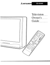
Front Control Panel
SYSIEM
RESET
©
11MER
Q
S-VIDEO VIDEO L-AUDIO-R
N,t_-5
Figure 1. Front Control Panel.
The buttons on the front control panel that are highlighted in gray are duplicated on the
remote control. The top row of labels show the control functions when there are no TV
menus displayed on the screen. The bottom row of labels show the control functions when
the TV menus are displayed on the screen. See Remote Control Functions: Overview,
page 60, for details on their functions.
System Reset
If the TV will not respond to either the remote control or the front panel controls and will
not power off, press the SYSTEM RESET button with a pointed item like the point of a
ball point pen. The TV will turn off and the TIMER light will a;h qui (kl yf (_ _bout me
minute. When the TIMER light stops a;hi _, y:)u rra y t urnon t l-eTV again [qe changes
you made while the TV was on before you used the SYSTEM RESET button may be
cancelled, however, the changes you made previously are not cancelled. Only the changes
since the last power on may be lost when the system reset button is pressed. All other
settings are retained.
Timer
The green light is a multi-function indicator. Each time the TV is plugged into the wall
electrical outlet, or when power is restored after a power failure, or after using the SYSTEM
RESET button, this light will a;h r api d yf (_ _bout me rri r_t e I_ not _tteTp t tot urn
on the TV during this period, wait for the a;hi _ t ost q0 bef (_eat teTp t i_ t ot urnt l'e TV
on. When the TV is turned on, the light will be illuminated steadily. If the TV has been
programmed to turn on automatically using the Timer feature, this light will a;h sled y
while the TV is powered off.
A/V Reset
Press this button to reset all A/V memories to the factory default settings.
Input 5
This input can be used for convenient connection of a camcorder or other video device to
the TV. Please note that if you connect to the S-VIDEO terminal, the VIDEO terminal is
deactivated. The VIDEO terminal is active when there is no S-Video connection.

Part I1: Installation
Back Panel
[]
[] Inputs 1-4
These inputs can be used for the connection of a VCR, Super VHS (S-VHS) VCR, DVD
player, standard satellite receiver, or other A/V device to the TV. Please note that if you
connect to the S-VIDEO terminal, the VIDEO terminal is deactivated. The VIDEO terminal is
active when there is no S-Video connection.
[] Output (Monitor and PIP)
The Monitor Output sends the TV audio and video signals from Ant-A, Ant-B and Inputs
1-5 to a VCR or other analog A/V equipment. It will also send digital audio and video
signals from Ant-DTV and IEEE-1394 products that are not copy protected, and convert
them to analog signals. From VGA, Component 1 and 2 and Input-DTV, no signals will be
sent. The PIP output sends the PIP's or POP's audio signal to an ampli e" or wi re e_s
headphones. If no PIP or POP is displayed, the PIP output will not send any audio.
[] Antenna (ANT-A, LOOP OUT, and ANT-B)
ANT-A and ANT-B receive analog NTSC signals from VHF/UHF antennas or an analog
NTSC cable system. LOOP OUT sends the ANT-A signal out to another component, such
as a cable box or VCR.
El IR Emitter-Repeater
Connecting IR emitters here allows the TV to pass IR commands from most IR remote
controls to other A/V devices that are out of range of the remote control.
!=! VGA
This input can be used for the connection of a computer.
73, for signal compatibility.
Please see Appendix B, page
11 Component Inputs 1-2
These inputs can be used for the connection of A/V equipment with component video
outputs, such as a DVD player. Please see Appendix B, page 73, for signal compatibility.
m DTV Input
This input is used to connect a DTV receiver, and can be con gJre:!f c_I-DTV s i _al t3pes
component (YPrPb), RGB sync on green, and RGB plus H&V. Please see Appendix B,
page 73, for signal compatibility.

Part I1: Installation
Back Panel
1tl Antenna DTV (ANT-DTV)
This input receives digital TV signals from a VHF/UHF antenna or unscrambled digital cable
system. If the TV receives scrambled signals on this input, it will not be able to decode
them. In this case, your cable company must provide a decoding box.
El IEEE-1394 Input/Output
These jacks allow the TV to connect to one or more external A/V products by means of a
single cable. Three jacks are provided for this purpose, which allow for a high degree of
ed I_lityfor cmnect i_ your s_st ento get her. Pl_se refer tothe Net (_ nma nd _-MGuide
for IEEE-1394 device connection details.
m Digital Audio Output
This output provides digital audio streams, such as Dolby Digital or other types of digital
audio, received in the signal from the ANT-DTV input or the IEEE-1394 devices. This output
is intended to be connected to an external audio receiver that is capable of decoding the
digital streams and converting them to analog signals suitable for driving loudspeakers.
ml IR Emitter-Home Theater Control Output
Two jacks are provided for connecting IR emitters. These emitters are used to control
external analog devices such as VCRs, DVDs, cable boxes, satellite receivers and audio
TM
receivers by means of the NetCommand features of the TV.
IB Memory Card
The card slot behind the cover allows the software of the TV to be updated with expanded
features by use ofa a;h cardpro_i d_dby M tsubi shi. [qe TVdoes not e3rre wi tha
card and does not require a card when it is rst recei _-=_!. "bu shoul dnot _tteTp t touse
a a;h cardt Pat isnot aut heriz_d by M tsubi shi • irsert any ot her iteni rt ot hi ssl d_a;
this may cause damage to your TV that is not covered by your warranty. When software
updates are available, they will be announced on our web site, www.mitsubishi-tv.com. If
you return your Owner's Registration card with your model and serial number, you may
receive written noti (at ira.

Part I1: Installation
Installation Con gJrations & Ne t (b nTna ndTMSe ttp
With this book you will ndf _ d cut pages t Pat show6 over vi evd i ajr a-m of _ andar d pre
established system connections, called con gJr _t ires. "_ese di ajr a_ speci fyt hei _ut s
to use on the TV and on the NetCommand TM supported Audio Video (A/V) Receivers.
Later pages in this book will show details on how to connect devices to individual TV
inputs.
Use the con gJr _t im t Pat re st d e_el yrra t ohes t hedevi e_s you wi sht oconnect tot he
TV. Connect those devices as closely as possible to the diagram. It is OK if you cannot
match the diagram perfectly. The NetCommand TM setup system will allow you to alter
the con _r _tim t orra t (h changes you need t orra ke. If y:)u do not Paveone of the
devices speci et i nt he con _ ati a0 the Ne CinTra n dTM set up s_st emwil Igve ycu the
option to select "None" for that device. As an example, if you do not have an A/V receiver,
connect the left and right stereo audio cables from each device directly to the TV. In the
NetCommand TM Setup system you will be given the opportunity to specify "None" for A/V
receiver and the TV will know to use the TV speakers for all sound. You can use brands
and/or models of devices that are not supported by NetCommand TM by selecting "Other".
Onthe ral _creenfe. thesetLpthereisan"F:dit'qotim. [qeeditq0timwi II_levyouto
change the settings; for instance you can select a different TV input or A/V receiver input
to use with a device, add a device that is not in the original con gJr _t ira, er _j _ea di fie" mt
name to the device. The setup can also be edited at a later date, from Setup in the TV
menu, to adjust to changes in your system.
For instructions concerning the connection and addition of IEEE 1394 devices to your
system, see the separate NetCommand TM Guide. The devices for each con gJr _tim are
shown in the table below.
NetCommand TM Setup Con gJr at ions
Configurations External Devices
Cable Cable Box Cable Box DBS VCR VCR 2 DVD Audio/Video Camcorder
and/or with With Audio Satellite player Receiver (temporary
Antenna channel 3, Video Receiver connection)
4, or 5 output
output
#1 • • • • •
#2 • • • •
#3 • • • • •
#4 • • • • • •
#5 • • • • • • •
#6 • • * • • • 0 •
Table 1.
*High De ri tim DBS Recei ,_r.

Part I1: Installation
NetCommand TM Supported Devices
Following is a list of devices by several manufacturers that have been tested and shown
to be compatible with the NetCommand TM control system. When you use these devices
you will be able to control them without changing the setting of the remote control from
TV to another product.
NetCommand TM Compatible Legacy Devices
Device/Model
Brand AV Receiver Cable Box DBS-Sat DVD Player VCR
Receiver
Mitsubishi M-VR800 SR-HD5 DD-6000 HS-U795**
Denon AVR_2700
6000
General Instruments CFT-2200
Hughes HIRD-E45
Jerrold See GI*
JVC HRo650U
Kenwood VR-2080
Motorola See GI*
Panasonic DVD-A310uic_ PV-8662
=
Pioneer VSX-D557 DV-414
RCA DRD480RE
Scientific Atlanta 8600
Sony $TR-DE825 SAT-A55 DVP-S500D SLV-778HF
Toshiba SD-9200
Yamaha RX-V2095
* No special models
** Supports both VCR-A and VCR-B remote control system
Since similar devices from the same manufacturer often operate the same way, other
models may be compatible, however they have not been tested so not all NetCommand TM
functions may be available. For devices that are not supported by NetCommand TM, you
will need to use that device's original remote control or program the TV remote to operate
these devices in the traditional manner.

Part I1: Installation
Connecting Antenna or Wall Outlet Cable for Digital Broadcasts
Antenna or
Wall Outlet Cable
ford
TV back panel
Antenna or Wall Outlet Cable for
Digital Broadcasts.
For cable or antenna with coaxial lead (Figure 1)
[] Connect the incoming cable to ANT-DTV
on the TV back panel.
Figure 1. Antenna or wall outlet cable.
Mitsubishi strongly recommends against using antennas with
twin _t le_ds. T_ n _t leadart ema wires are sLbj ect to
interference which may adversely affect the performance of the
TV. We recommend using coaxial antenna cable.

Part I1: Installation
Connecting an Analog Antenna, Wall Outlet Cable, or Cable
Box .......... o.........
(Channels 213) (Channels 14-69)
Separate UHF and VHF Antennas
(Figure 1)
[] Connect the UHF and VHF antenna
leads to the UHF/VHF combiner.
[] Push the combiner onto ANT-A on the
TV back panel.
[] UHF/VHF combiners are not provided
with the TV. They should be available at
most electronic stores.
Mitsubishi strongly recommends against using antennas with
twin _t le_ds. T_ n a led art ema wi" esare sLbj e_ to
interference which may adversely affect the performance of the
TV. We recommend using coaxial antenna cable.
Fla[ T
Fla[ Twin Lead
Extema_ TV back panel
Antenna
or Cable
3%%to
Combiner
m_Back Side
Figure 1. Connecting separate UHF and VHF antennas.
Antenna or Wall Outlet Cable for
Analog Broadcasts.
(Figure 2)
For antennas with twin _t lead
[] For antenna with twin _t IsBds, connect
the 300-Ohm twin leads to the trans-
former.
[] Push the 75-Ohm side of the transformer
onto ANT-A on the TV back panel.
300-Ohm to 75-Ohm matching trans-
formers are not provided with the TV.
They should be available at most elec-
tronic stores.
For cable or antenna with coaxial lead
I_1 Connect the incoming cable to ANT-A on
the TV back panel.
Mitsubishi strongly recommends against using antennas with
twin _t le_ds. T_ n a led art ema wi" esare sLbj e_ to
interference which may adversely affect the performance of the
TV. We recommend using coaxial antenna cable.
300 Ohm Fin _ 75 Ohm
Twin Lead C_Ial Cable
TV back
Optlonai 300 Ohm to 75 Ohm
Matching Transferor
Figure 2. Connecting antenna or wall outlet cable for
analog broadcasts.
Cable Box
(Figure 3)
Incoming
Cable
[] Connect the incoming cable to ANT-A on
the TV back panel.
Connect two coaxial cables as follows:
One from LOOP-OUT on the TV back panel to
[] IN on the cable box back panel.
I_1 One from OUT on the cable box back panel to
ANT-B on the TV back panel.
Figure 3.
[]
Connecting the cable box.

Part I1: Installation
Connecting an Analog VCR
Analog Antennas or Wall Outlet
Cable
(Figure 1)
VCR back panel
Figure 1. Connecting VCR with antennas or wall outlet
cable.
[] Connect the incoming cable to ANT-A on
the TV back panel.
[] Connect two coaxial cables as follows:
[] One from LOOP-OUT on the TV back panel to
ANTENNA IN on the VCR back panel.
[] One from VCR back panel ANTENNA OUT to
ANT-B on the TV back panel.
m Now complete gJre3, st_ps 1-2
Cable Box
(Figure 2)
[] Connect the incoming cable to ANT-A on
the TV back panel.
Connect three coaxial cables as follows:
[] One from LOOP-OUT on the TV back panel to
IN on the back of the cable box.
[] One from OUT on the back of the cable box to
ANTENNA IN on the VCR back panel.
L/fl One from ANTENNA OUT on the VCR back
panel to ANT-B on the TV back panel.
DI Now complete gJre3, st_ps 1-2
Adding Composite Video or
S-Video with Audio Connections
(Figure 3)
Figure 2. Connecting VCR with cable box.
VCR back panel
Ifyour VCR has a video (,:
channel or RF ON/OFF ©U[
switch, set to OFE
Figure 3. Connecting the VCR AudiolVideo.
[] Connect a video cable from VIDEO
OUT on the VCR back panel to VIDEO
INPUTS 1, 2, 3, or 4 on the TV back
panel.
If you have a S-VHS VCR, follow the same
steps using the S-Video terminals on the VCR
and TV (in place of the composite terminals).
[] Connect a set of audio cables from
AUDIO OUT on the VCR back panel to
AUDIO INPUT 1, 2, 3, or 4 on the TV
back panel. The red cable connects to
the R (right) channel and the white cable ...........................................................
connects to the L (left) channel. If your
VCR is mono (non-stereo), connect only
the white (left) cable.

Part I1: Installation
Connecting an Audio/Video Surround Sound Receiver
Connecting an A/V Receiver
(Figure 1)
B
€:
B
Connect a video cable from Monitor VIDEO
OUTPUT on the back of the TV to the TV
VIDEO INPUT on the back of the A/V Receiver.
If you have connected a S-VHS VCR to the
A/V Receiver, then follow the same video
connection using the S-Video cable and
terminals on the TV and A/V Receiver (in
place of the VIDEO cable).
Connect a set of audio cables from the Monitor
AUDIO OUTPUT on the back of the TV to the
TV AUDIO INPUT on the back of the A/V
Receiver. The red cable connects to the R
(right) channel and the white cable connects
to the L (left) channel.
If connecting a digital A/V Receiver with Dolby
Digital TM surround sound.
I_1 Connect one end of the digital audio cable sup-
plied with the TV to the DIGITAL AUDIO
OUTPUT on the back of the TV (connect
the end of the cable with the ferrite or plastic
cylinder). Connect the other end to the
COAXIAL DIGITAL INPUT on the back
of the A/V Receiver. Check the Owner's
Guide for the A/V Receiver for information
concerning the use of the digital input and
switching between the digital sound and analog
stereo sound from the TV.
Ferrite end
Use only if connecting a Dolby Digital AN Receiver
TV Rear Panel
®®®®
®®®®
®@®®
O ,,,_@,,O
[]
m
[]
Attach only one
cable type c_
A/V Receiver Rear Panel
[]
Figure 1. Connecting an Audio/Video Receiver
/