
iNSTALLATiON AND SERVICEMUST BE PERFORMED BY A QUALiFiED iNSTALLER.
iMPORTANT: SAVE FOR LOCAL ELECTRICALiNSPECTOR'S USE.
READ AND SAVE THESE iNSTRUCTiONS FOR FUTUREREFERENCE.
If the information in this manual is not followed exactly, a fire or
explosion may result causing property damage, personal injury or death.
FOR YOUR SAFETY:
-- Do not store or use gasoline or other flammable vapors and liquids in the
vicinity of this or any other appliance.
-- WHATTO DO IFYOU SMELLGAS:
• Do not try to light any appliance.
• Do not touch any electrical switch; do not use any phone in your building.
• Immediately call your gas supplier from a neighbor's phone. Follow the
gas supplier's instructions.
• If you cannot reach your gas supplier, call the fire department.
-- Installation and service must be performed by a qualified installer,
service agency or the gas supplier.
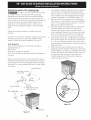
Appliances Installed in the
state of Massachusetts:
This Appliance can only be
installed in the state of
Massachusetts by a
Massachusetts licensed plumber
or gasfitter.
This appliance must be installed
with athree (3) foot / 36 in. long
flexible gas connector.
A"T" handle type manual gas
valve must be installed in the gas
supply line to this appliance.
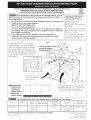
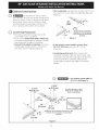
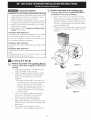
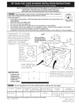
For existing 29" (73.7 cm) cutout
width opening, you must call the
Service Center for optional thinner
side panels. Also you must prepare
the countertop edge as shown in the
"Countertop Preparation" section
(see page 5).
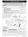
I Y2" Max.
Shave Raised (3.8 cm Max.
Edgeto Clear
Space for a
31s/_e,,min
(81 cm)
Wide
Cooktop.
DimensionC in
table.
These surfaces should
be flat & leveled
(hatched area
1/2" Min._
5" Min
30" Min.
76.2 cm Min.
18" Min.
(45.7 cm) Min.
\13"
(33 cm)
IMPORTANT:
Cabinet and
countertop
width should
match the
cutout width.
Locate Cabinet Doors
1" (2.5 cm) Min. from
Cutout Opening.
E
E
24" Min.
(61 cm Min.)
Grounded Jorlction Box or Wall Outlet
Should BeLocated 8" to 17" (20.3 cm to
43.2 cm) From Right Cabinet and 2" to
4" (5.1 cm to 10.2 cm) From Floor.
Do not install the unit in the cabinet before reading next two pages.
A. HEIGHT B. WIDTH' C, COOKTOP DIDEPTHTO E. CUTOUTWIDTH*** F. CUTOUT G. HEIGHT
30" (76,2 cm) Porcelain
31 5/16" (79.5 cm)
Glass
3I 1/2" (8I cm)
28 5/I6" (71,9 cm)
30±1/16"
(76,2±0,I 5 cm}
35 518" (90.5 cm} -
36 518" (93 cm}
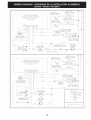
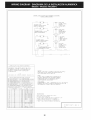
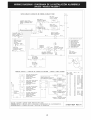
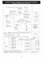
NOTE: Wiring diagram for these appliances are enclosed in this booklet.
Printed in United States
21 3/4" (55,2 cm} Min. 36 5/8" (93 cm) Max.
22 I/8" (56,2 cm) Max 35 5/8" (90.5cm} Min.
24" (61 cm) Min. with
backguard
P/N 318201674 (0604) Rev. D
English - pages 1-14
Espahol - paginas 15-28
Wiring Diagrams - pages 29-32

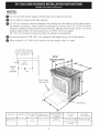
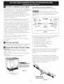
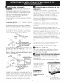
NOTES:
O Do not pinch the power supply cord between the range and the wall.
Do not seal the range to the side cabinets.
24" (61 cm) minimum clearance between the cooktop and the bottom of the cabinet when
the bottom of wood or metal cabinet is protected by not less than 1/4" (0.64 cm) flame
retardant millboard covered with not less than No. 28 MSG sheet metal, 0.015" (0.4 mm)
stainless steel, 0.024" (0.6 mm) aluminum, or 0.020" (0.5 mm) copper.
30" (76.2 cm) minimum clearance when the cabinet is unprotected.
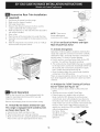
For cutouts below 22 7/8"(58.1 cm), appliance will slightly show out of the cabinet.
Allow at least 19 ¼" (48.9 cm) clearance for door depth when it is open.
22 7/8" (58.1 cm) min.
23 1/4" (59.05 cm) max.
_!_-- (see Note 4) ---_
11/8"
(2.86 cm)
FRONT
OF _ F
CABINET Ref.
Door Open
(see note 5)
/
t j
21¾"
(55.25 crn)_'1
A
Side Panel
A. HEIGHT B. WIDTH
35 5/8" (90.5 cm)- 30" (76,2 cm)
36 5/8" (93 cm)
I
C. COOKTOP D. DEPTH TO
31 5116" 28 5/16" (71,9 cm)
(79.5 cm}
I
E. CUTOUT WIDTH *** F. CUTOUT G. HEIGHT
30±1/16" 21 3/4" (55,2 cm) Min. 365/8" (93 cm} Max.
(76,2±0,15 cm} 22 1/8" (56,2 cm) Max 35 5/8" (90.5 cm) Min.
24" (61 cm) Min. with
backguard

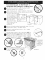
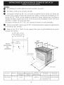
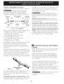
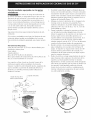
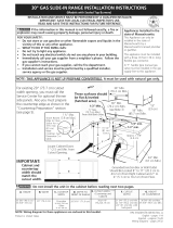
To avoid breakage: Do NOT handle or
manipulate the unit by the cooktop glass.
The counter-top around the cut-out should be flat and
leveled (see hatched area on illustration 1).
Before installing the unit, measure the heights of the two (2)
cabinet sides (H1-4), front and back (see illustration 1) from the
floor to the top of the counter.
Level the range using the
four (4)leveling legs so
that the height from the
floor to the underside of
the cooktop glass is
greater than the tallest
cabinet measurement by
at least 1/16" (see
Shave
Raised
Edge
to Clear
Space for,
31Y2" (81 cm) Wic
Cooktop.
illustration 2).
1 Y2"Max. 1
(3.8cm Max.) I
Illustration 1
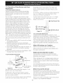
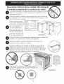
Slide the unit into the cabinet. Make sure the center of the unit is
aligned with the center of the cabinet cut-out.
Remove the protective channels on each side of the glass
cooktop (if provided).
The metal flange under each side of the cooktop MUST be
placed over the cabinet countertop for proper unit support.
The glass cooktop should NOT directly touch the countertop
(see illustration 2) or could cause glass breakage voiding the
warranty. Level the unit if needed.
After the installation, MAKE SUREthat the
is supported by the leveling legs NOT by the
cooktop.
_.:
.To successfully install
the range, the initial
level height from floor
to underside of
cooktop glass should
be at least 1/16" taller
than cabinet sides as
measured in step 1.
Illustration 2

Important Notes to the Installer
1. Read all instructions contained in these installation
instructions before installing range.
2. Remove all packing material from the oven
compartments before connecting the gas and electrical
supply to the range.
3. Observe all governing codes and ordinances.
4. Be sure to leavethese instructions with the consumer.
Important Note to the Consumer
Keep these instructions with your Use & Care Guide for
future reference.
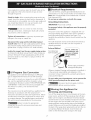
• Do not obstruct the flow of combustion air at the
oven vent nor around the base or beneath the
lower front panel of the range. Avoid touching the
vent openings or nearby surfaces as they may become
hot while the oven is in operation. This range requires
fresh air for proper burner combustion.
Never leave children alone or
unattended in the area where an appliance is in use.
As children grow, teach them the proper, safe use of all
appliances. Never leave the oven door open when the
range is unattended.
IMPORTANT SAFETY
INSTRUCTIONS
Installation of this range must conform with local codes
or, in the absence of local codes, with the National Fuel
Gas Code ANSI Z223.1/NFPA .54-latest edition.
This range has been design certified by CSA
International. As with any appliance using gas and
generating heat, there are certain safety precautions you
should follow. You will find them in the Use and Care
Guide, read it carefully.
• Be sure your range is installed and grounded
properly by a qualified installer or service
technician.
• This range must be electrically grounded in
accordance with local codes or, in their absence,
with the National Electrical Code ANSI/NFPA No.
70--latest edition. SeeGrounding Instructions.
• Before installing the range in an area covered with
linoleum or any other synthetic floor covering,
make sure the floor covering can withstand heat at
least 90°F above room temperature without
shrinking, warping or discoloring. Do not install the
range over carpeting unless you place an insulating pad
or sheet of Y4"(10,16 cm) thick plywood between the
range and carpeting.
• Make sure the wall coverings around the range
can withstand the heat generated by the range.
All ranges
cantip.
Injuryto
persons could
result.
Install anti-tip
device
packed with
range.
I_ Toreduce
the risk of tipping of the
range, the range must be
secured by properly
installed anti-tip bracket
provided with the range.
To check if the bracket is
installed properly, grasp
the top rear edge of the
range and carefully tilt it
forward to make sure the
range isanchored.
Stepping, leaning or sitting on the
doors or drawers of this range can result in serious
injuries and can also cause damage to the range.
• Do not store items of interest to children in the
cabinets above the range. Children could be seriously
burned climbing on the range to reach items.
To eliminate the need to reach over the surface
burners, cabinet storage space above the burners
should be avoided.
• Adjust surface burner flame size so it does not
extend beyond the edge of the cooking utensil.
Excessive flame is hazardous.
• Do not use the oven as a storage space. This
creates a potentially hazardous situation.
• Never use your range for warming or heating the
room. Prolonged use of the range without adequate
ventilation can be dangerous.
Do not store or use gasoline or other flammable
vapors and liquids near this or any other
appliance. Explosions or fires could result.
In the event of an electrical power outage, the surface
burners can be lit manually. To light a surface burner,
hold a lit match to the burner head and slowly turn the
Surface Control knob to LITE.Use caution when
lighting surface burners manually.
• Reset all controls to the "off" position after using
a programmable timing operation.
FOR MODELS WITH SELF-CLEAN FEATURE:
• Remove broiler pan, food and other utensils
before self-cleaning the oven. Wipe up excess
spillage. Follow the precleaning instructions in the Use
and Care Guide.
• Unlike the standard gas range, THIS COOKTOP IS
NOT REMOVABLE. Do not attempt to remove the
cooktop.

©
©
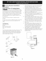
Cabinet Construction
To eliminate the risk of cabinet
burns and fire, do not have cabinet storage space
above the range. If there is cabinet storage space
above range, reduce risk by installing a range
hood that projects horizontally a minimum of 5"
(12.7 cm) beyond the bottom of the cabinet.
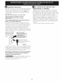
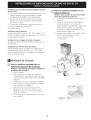
Cou ntertop Preparation
• The cooktop sides of the range fit over the
cutout edge of your countertop.
• If you have a square finish (flat) countertop,
no countertop preparation is required. Cooktop
sides lay directly on edge of countertop.
• Formed front-edged countertops must have
molded edge shaved flat 3/4" (1.9 cm) from
each front corner of opening (Figure 2).
• Tile countertops may need trim cut back 3/4"(1.9 cm)
from each front corner and/or rounded edge flattened
(Figure 2).
Min.
Cutout
Width
(1.9 cm)
I
(1.9cm)
311/z'_
(81 cm)
Formed or tile countertop
trimmed %" (1,9 cm) back at
front corners of countertop
opening.
Figure 2
• if the existing cutout width is greater than
30-1116" (76,4 cm), reduce the 3A" (I .9 cm)
dimension.
Countertop must be level. Placea level on the
countertop, first side to side, then front to back. If the
countertop is not level, the range will not be level. The
oven must be levelfor satisfactory baking results.
Cooktop sides of range fit over edges of countertop
opening.
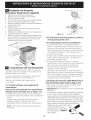
Q • For cutout width of
existing
29" (73.7 cm) (Figure 3):
You must also clear 2 3/16"
(5,56 cm) of material from
front of countertop,
11/4"
.(3.2 cm)

Provide an adequate Gas Supply
When shipped from the factory, this unit is designed to
operate on 4"(10,16 cm) water column (1.0 kPa) Natural
gas manifold pressure. A convertible pressure regulator is
connected to the range manifold and MUST be
connected in series with the gas supply line. If LP/
Propane conversion kit has been used, follow instructions
provided with the kit for converting the pressure
regulator to LP/Propane use.
Care must be taken during installation of range not to
obstruct the flow of combustion and ventilation air.
Forproper operation, the maximum inlet pressure to the
regulator should be no more than 14"(35,S6 cm) of
water column pressure (3.5 kPa). The inlet pressure to
the regulator must be at least 1" (.25 kPa) greater than
the regulator manifold pressure setting. Examples: If
regulator isset for natural gas 4" (10,16 cm) manifold
pressure, inlet pressure must be at least 5"(12.60 cm); if
regulator has been converted for LP/Propane gas
10"(25,4 cm) manifold pressure, inlet pressure must be
at least 11 "(27,9 cm).
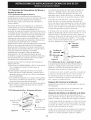
Connection to Pressure ReguJator
The regulator is already installed on the appliance.
Do not make the connection too tight.
The regulator is die cast. Overtightening may crack the
regulator resulting in a gas leak and possible fire or
explosion.
Manual GAS FLOW Pressure
Shutoff Flare _ Flare Regulator
Valve Union Union
On, t t t
Nipple Flexible Nipple Access
Off Connector
Cap
All connections must be wrench-tightened
Figure 5
Leak testing of the appliance shall be conducted
according to the instructions in step 4.
The gas supply line should be Y2" or sA" I.D. (Interior
Diameter)
Seal the openings
Seal any openings in the wall behind the range and in the
floor under the range after gas supply line is installed.
Connect the range to the gas suppJy
Important: Remove all packing material and
literature from range before connecting gas and
electrical supply.
To prevent leaks, put pipe joint sealant on all external
pipe threads.
Your regulator is in location shown below.
Do not
allow regulator to
rotate on pipe when
tightening fittings.
Assemble the flexible connector from the gas supply pipe
to the pressure regulator in the following order:
1. manual shutoff valve (not included)
2. I/2" nipple (not included)
3. 1/2" flare union adapter (not included)
4. flexible connector (not included)
5. 1/2" flare union adapter (not included)
6. I/2" nipple (not included)
7. pressure regulator (included)
Use pipe-joint compound made for use with Natural and
LP/Propane gas to seal all gas connections. If flexible
connectors are used, be certain connectors are not
kinked.
The supply line must be equipped with an approved
manual shutoff valve. This valve should be located in the
same room as the range and should be in a location that
allows ease of opening and closing. Do not block access
to the shutoff valve. The valve is for turning on or
shutting off gas to the appliance.
t_
PRESSURE REGULATOR
LOCATION
Figure 4
Shutoff Valve =
Open position
Figure 6

Onceregulatorisinplace,opentheshutoffvalveinthe
gassupplyline.Waitafewminutesforgastomove
throughthegasline.
Checkfor leaks.Afterconnectingtherangetothegas
supply,checkthesystemforleakswithamanometer.If
amanometerisnotavailable,turnonthegassupplyand
usealiquidleakdetector(orsoapandwater)atall
jointsandconnectionstocheckforleaks.
Electrical Requirements
120 volt, 60 Hertz, properly grounded dedicated circuit
protected by a 15 amp circuit breaker or time delay fuse.
Note: Not recommended to be installed with a Ground
Fault Interrupt (GFI).
Do not use an extension cord with this range.
Grounding Instructions
IMPORTANT Please read carefully.
Do not use a flame to check for leaks
from gas connections. Checking for leaks with a flame
may result in a fire or explosion.
Tighten all connections as necessary to prevent gas
leakage in the range or supply line.
For personal safety, this appliance must be properly
grounded.
The power cord of this appliance is equipped with a 3-
prong (grounding) plug which mates with a standard 3-
prong grounding wall receptacle (see Figure 7) to
minimize the possibility of electric shock hazard from the
appliance.
Disconnect this range and its individuaJ manuaJ
shutoff valve from the gas supply piping system during
any pressure testing of that system at test pressures
greater than I/2 psig (3.5 kPa or 14" water column).
isolate the range from the gas supply piping system
by closing its individual manual shutoff valve during any
pressure testing of the gas supply piping system at test
pressures equal to or less than I/2 psig (3.5 kPa or 14"
water column).
The wall receptacle and circuit should be checked by a
qualified electrician to make sure the receptacle is
properly grounded.
Preferred Method
Grounding type
wall receptacle
Do not, under any
circumstances, cut,
remove, or bypass
the grounding
prong.
LPIPropane Gas Conversion
Thisappliance can be usedwith Natural gasor LP/Propane
gas. It isshippedfrom the factory for usewith natural gas.
If you wish to convert your range for use with LP/Propane
gas, use the supplied fixed orifices located in a bag
containing the literature marked "FOR LP/PROPANEGAS
CONVERSION." Follow the instructions packaged with
the orifices for surface, oven and broil burners
conversion.
The conversion must be performed by a qualified service
technician in accordance with the manufacturer's
instructions and all local codes and requirements. Failure
to follow these instructions could result in serious injury
or property damage. The qualified agency performing
this work assumes responsibility for the conversion.
Failure to make the appropriate
conversion can result in serious personal injury and
property damage.
Figure 7
Power supply cord with 3-
prong grounding plug.
Where a standard 2-prong wall receptacle is installed, it
isthe personal responsibility and obligation of the
consumer to have it replaced by a properly grounded 3-
prong wall receptacle.
Do not, under any circumstances, cut or remove the
third (ground) prong from the power cord.
Disconnect electrical supply cord from
wall receptacle before servicing cooktop.
Moving the Appliance for
Servicing and Cleaning
Turn off the range line fuse or circuit breakers at the main
power source, and turn off the manual gas shut-off valve.
Make sure the range iscold. Remove the service drawer
(warmer drawer on some models) and open the oven door.
Lift the range at the front and slide it out of the cut-out
opening without creating undue strain on the flexible gas
conduit. Make sure not to pinch the flexible gas conduit at
the back of the range when replacing the unit into the cut-
out opening. Replacethe drawer, close the door and
switch on the electrical power and gas to the range.

Range Installation
Important Note: Door removal is not a requirement for
installation of the range, but is an added convenience,
Refer to the Use and Care E
Guide for oven door
removal instructions.
Standard Installation
_The range cooktop overlaps the countertop at the
sides and the range rests on the floor. The cooktop is
31 I/2" (81 cm)wide.
Install base cabinets 30" (76.2 cm) apart. Make sure
_they are plumb and level before attaching cooktop.
Shave raised countertop edge to clear 31 I/2" (81
cm) wide range top rim.
i_lnstall cabinet doors 31 " (78.7 cm) min. apart so it
F
will not interfere with range door opening.
Slide the range into the cutout opening and center it
before leveling it.
Level the range (see section 9). The floor where
the range is to be installed must be level. Follow the
instructions under "Leveling the Range- Models
Equipped with Leveling Device".
Adjust leveling legs so that the underside of the
cooktop issitting on the countertop. Carefully screw
in (refer to Leveling the range: Models equipped
with Leveling Device") the back leveling leg until the
cooktop glass overhang touches slightly the
countertop. Then carefully screw in the front two
leveling legs until the cooktop glass overhang
touches slightly the countertop.
For models equipped with Leveling Leg only (no
leveling device):
Make sure the four leveling legs (front and rear) are
setup higher than the height of the cabinet (shown
on page 3).
Cutout countertop exactly as shown on page 1.
For models equipped with Leveling Device:
Make sure the front leveling legs and the rear
leveling device are setup higher than the height of
the cabinet (shown on page 3).
Install the anti-tip bracket at this
point before placing the range at its final
position. Follow the installation instructions on page
12 or on the anti-tip bracket template supplied with
the range.
To provide an optimum installation, the top surface
of the countertop must be level and flat (lie on the
same plane) around the 3 sides that are adjacent to
range cooktop. Proper adjustments to make the top
flat should be made or gaps between the countertop
and the range cooktop may occur.
_ To reduce the risk of damaging your
appliance, do not handle or manipulate it by the
ceramic glass. Manipulate with care.
Position range in front of the cabinet opening.
Make sure that the cooktop glass which overhangs
' the countertop clears the countertop. If necessary,
raise the unit by lowering the leveling legs.
Install the anti-tip bracket at this
point before placing the range at its final
position, Follow the installation instructions on page
12 or on the anti-tip bracket template supplied with
the range.
To provide an optimum installation, the top surface
of the countertop must be level and flat (lie on the
same plane) around the 3 sides that are adjacent to
range cooktop. Proper adjustments to make the top
flat should be made or gaps between the countertop
and the range cooktop may occur.
To reduce the risk of damaging your
appliance, do not handle or manipulate it by the
ceramic glass. Manipulate with care.
Position range in front of the cabinet opening.
Make sure that the glass which overhangs the
countertop clears the countertop. If necessary, raise
the unit by lowering the leveling legs.
Level the range (see section 9). The floor where
the range is to be installed must be level. Follow the
instructions under "Leveling the Range-Models
Equipped with Leveling Legs".
Slide the range into the cutout opening.

If Accessories Needed :
Installation For 29" Existing Cutout Width Opening
1. You must replace the actual side trims by new and
smaller side trims. These new side panels can be
ordered through a Sears Service Center.
2. Follow instructions supplied with your new side trim_
to replace the actual side trims with the new ones.
3. Check if the countertop is prepared for 29" cutout
wide opening at page 7.
4. Install range as in the "installation Without Side
Panels" section above.
installation With Backguard
A backguard kit can be ordered through a Sears Service
Center.The cutout depth (21 3/4" (55.2 cm) Min.,
22 I/8" (56.2 era) Max.) needs to be increased to24"
(61 cm) when installing a backguard
Installation With End Panel
An end panel kit can be ordered through a Sears Servio
Center.
Installation With Side Panel
A side panels kit can be ordered through a Sears Servio
Center.
Install cabinet doors 31 " (78.7 cm) rain. apart so as not
to interfere with range door opening.
Leveling the Range
ModeJs Equipped with Leveling Device
Level the range after installation in the cutout
opening.
I. Open the range drawer. The leveling screws
control the height of the rear leg.
2. Adjust the appliance legs as follows until the
underside of the cooktop (or cooktop glass)
surface is sitting level on the countertop
(Figure 8).
a.To adjust the front legs, use a wrench on
the leg base and turn counterclockwise to
lower or clockwise to raise the range.
b.To adjust the rear legs, use a ratchet or a
nutdriver and turn the leveling screws
counterclockwise to lower or clockwise to
raise the range.
3. Check if the range is level by installing an
oven rack in the center of the oven and
placing a level on the rack (Figure 9).
4. Take 2 readings with the level placed
diagonally in one direction and then the other.
Level the range, if necessary, by adjusting the
leveling legs.
5. If the range cannot be level, contact a
carpenter to correct sagging or sloping floor.
Models Equipped with Leveling Leg_s
Level the range and set cooktop height before
installation in the cut-out opening.
I. Install an oven rack in the center of the oven.
2. Place a level on the rack (see Figure 9). Take 2
readings with the level placed diagonally in one
direction and then the other. Level the range, if
necessary, by adjusting the 4 leg levelers with a
wrench (see Figure 18).
3. Taking care to not damage the countertop, slide
range into cutout opening and double check for
levelness.
Jst Rear Levelim
Leveling
Font
Leveling
Leg
LOWER
RAISE
Figure 8
J @
Figure 9

Decorative Rear Trim instaJlation
(if required)
1. Disconnect the power from the range.
2. Make sure the range is leveled.
3. Pull range toward you.
4. Measure the distance between the floor and the
surface underneath the cooktop frame.
5. Mark that distance on the wall where the decorative
trim will be installed.
6. Draw a line.
7. Place the top of the decorative trim under that line.
8. Using the screws provided fix the decorative trim into
the wall.
9. Slide the range back into position as far as it will go
and reconnect the power source.
Figure 10
Check Operation
Refer to the Use and Care Guide packaged with the
range for operating instructions and for care and
cleaning of your range.
Remove all packaging from the oven before testing.
11.1 Install Burner Bases and Burner Caps
This range is equipped with sealed burners
as shown (see Figure 11).
a. Unpack burner bases and burner caps.
b. Place burner bases over each gas opening.
c. Make sure the burner is properly aligned and leveled.
Place burner caps over appropriate burner bases.
NOTE: There are no
burner adjustments
necessary on this range.
Open ng
Electrode
Figure 11
11.2 Turn on Electrical Power and Open
Main Shutoff Gas Valve
11.3 Check the Igniters
Operation of electric igniters should be checked after
range and supply line connectors have been carefully
checked for leaks, and range has been connected to
electric power. To check for proper lighting:
a.Push in and turn a surface burner knob to the LITE
position. You will hear the igniter sparking.
b. The surface burner should light when gas is available
to the top burner. Each burner should light within four
(4) seconds after air has been purged from supply
lines. Visually check that burner has lit.
c. Once the burner lights, the control knob should be
rotated out of the LITEposition.
There are separate ignition devices for each burner. Try
each knob separately until all burner valves have been
checked.
11.4 Adjust the "LOW" Setting of Surface
Burner Valves (see Figure 12)
a.Push in and turn each control to LITE until burner
ignites.
b. Quickly turn knob to LOWEST POSITION.
c. If burner goes out, readjust valve as follows:
Reset control to OFF. Remove the surface burner
control knob, insert a thin-bladed screw driver into
the hollow valve stem and engage the slotted screw
inside. Flame size can be increased or decreased with
the turn of the screw. Adjust flame until you can
quickly turn knob from LITEto LOWEST POSITION
without extinguishing
the flame. Flame
should be as small as
possible without
going out.
Figure 12
10

11.5 Operation of Oven Burners and Oven
Adjustments
11.5.1 Electric ignition Burners
Operation of electric igniters should be checked after
range and supply line connectors have been carefully
checked for leaks, and range has been connected to
electric power.
The oven burner isequipped with an electric control
system aswell asan electric oven burner igniter. If your
model isequipped with a waist-high broil burner igniter, it
will also have an electric burner igniter. These control
systems require no adjustment. When the oven is set to
operate, current will flow to the igniter. It will "glow"
similar to a light bulb. When the igniter has reached a
temperature sufficient to ignite gas, the electrically
controlled oven valve will open and flame will appear at
the oven burner. There is a time lapse from 30 to 60
seconds after thermostat is turned ON before the flame
appears atthe oven burner. When the oven reaches the
display setting, the glowing igniter will go off. The burner
flame will go "out" in 20 to 30 seconds after igniter goes
"OFF". To maintain any given oven temperature, this
cycle will continue as long asthe display is set to operate.
After removing all packing materials and literature from
the oven:
a) Set the oven to BAKE at 300°F. See Use & Care Guide
for operating instructions.
b) Within 60 seconds the oven burner should ignite.
Check for proper flame, and allow the burner to cycle
once. Resetcontrols to off.
c) If your model isequipped with a high-waist broiler, set
oven to broil. See Use & Care Guide for operating
instructions.
d) Within 60 seconds the broil burner should ignite. Check
for proper flame. Resetcontrols to off.
11.5.2 Air Shutter-Oven Burner
j ./../.
L wer: gh Burner
Oven Baffle i
(removable
Lower Oven Bottom
Figure 13 _"-Air Shutter (removable)
The approximate oven burner flame length is 1 inch
(distinct inner cone of blue flame).
To determine if the oven burner flame is proper,
remove the oven bottom and burner baffle and set
the oven to bake at 300%.
To remove the oven bottom, remove oven hold down
screws at rear of oven bottom. Pull up at rear,
disengage front of oven bottom from oven front
frame, and pull the oven bottom out of the oven.
Remove burner baffle so that burner flame can be
observed.
If the flame is yellow, increase air shutter opening size
(see "2" in Figure 14). If the entire flame is blue,
reduce the air shutter opening size.
To adjust frame loosen lock screw (see "3" in Figure
14), reposition air shutter, and tighten lock screw.
Replace oven bottom.
Lock Screw.41_.,t !_I1_ Oven Burner Tube
@FigureAirShutter._ 91_14 @ Orifice Hood
11.5.3 Air Shutter-Broil Burner
The approximate flame length of the burner is 1 inch
(distinct inner cone of blue flame). To determine if the broil
burner flame is proper, set the oven to broil. If flame is
yellow, increase air shutter opening size (see "2" in Figure
14). If the entire flame is blue, reduce the air shutter
opening size. To adjust, loosen lock screw (see "3" in
Figure 14), reposition air shutter, and tighten lock screw.
When All Hookups are Complete
Make sure all controls are left in the OFFposition.
Make sure the flow of combustion and ventilation air to
the range is unobstructed.
Model and Serial Number Location
The serial plate is located on the oven front frame
behind the oven door (some models or on the drawer
side frame (some models).
When ordering parts for or making inquiries about your
range, always be sure to include the model and serial
numbers and a lot number or letter from the serial plate
on your range.
Your serial plate also tells you the rating of the burners,
the type of fuel and the pressure the range was adjusted
for when it left the factory.
Before You Call for Service
Read the Before You Call Checklist and operating
instructions in your Use and Care Guide. It may save you
time and expense. The list includes common occurrences
that are not the result of defective workmanship or
materials in this appliance.
Refer to your Use & Care Guide for Sears service phone
numbers or call 1-800-4-MY-HOME ®.
11

Anti-Tip Brackets installation
Instructions
Models Equipped with Leveling Device
To reduce the risk of tipping of the range,
the range must be secured to the floor by properly installed
anti-tip bracket and screws packed with the range. These
parts are located in the oven. Failure to install the anti-tip
bracket will allow the range to tip over if excessiveweight
is placed on an open door or if a child climbs upon it.
Serious injury might result from spilled hot liquids or from
the range itself.
Follow the instructions below to install the anti-tip
brackets.
If range is ever moved to a different location, the anti-tip
brackets must also be moved and installed with the
range.
Tools Required:
Adjustable Wrench
Ratchet
Drill & I/8"(0,32 cm) bit
5/16" (0,8 cm) Nutdriver
Level
The anti-tip bracket attaches to the floor at the back of the
range to prevent range from tipping. When fastening
bracket to the floor, be sure that screws do not penetrate
electrical wiring or plumbing. The screws provided will
work in either wood or concrete.
1. Draw a center line (CL) on the floor where the range
should be installed. Also draw a line on the floor at
the range back position if there is no wall.
2. Unfold paper template and place it flat on the floor
with the right rear corner positioned exactly on the
intersection of the center and back lines you just drew
before. (Use the diagram below to locate brackets if
template is not available (Figure 15)).
3. Mark on the floor the location of the 4 mounting holes
shown on the template. Foreasier installation, 3/
16"(0,48 cm) diameter pilot holes 1/2"(1,27 cm) deep
can be drilled into the floor.
4. Remove template and place bracket on floor. Line up
holes in bracket with marks on floor and attach with 4
screws provided. Bracket must be secured to solid floor
(Figure 16). If attaching to concrete floor, first drill 3/
16"(0,48 cm) dia. pilot holes using masonry drill bit.
5. Be sure the 4 leveling legs are at the highest position
they can be.
6. Slide range into place making sure structure of the
range istrapped by the anti-tip bracket (Figure 15).
Lower the range by adjusting the 4 leveling legs until
the underside of the cooktop is sitting level on the
countertop. Referto "Leveling the Range" section.
7. After installation, verify that the anti-tip bracket is
engaged by grasping the top rear edge of the range and
carefully attempt to tilt it forward to make surerange is
properly anchored.
Kitchen
Cabinet
Screws
Figure 16
BAC K
Figure 15
12

ModeJs Equipped with Leveling leg_s
To reduce the risk of tipping of the range,
the range must be secured to the floor by properly
installed anti-tip brackets and screws packed with the
range. These parts are located in a plastic bag in the
oven. Failure to install the anti-tip brackets will allow the
range to tip over if excessive weight is placed on an
open door or if a child climbs upon it. Serious injury
might result from spilled hot liquids or from the range
itself.
Follow the instructions below to install the anti-tip
brackets.
If range is ever moved to a different location, the anti-tip
brackets must also be moved and installed with the
range. To check for proper installation, see step 5.
Tools Required:
5/16" (0,79 cm) Nutdriver or Flat Head Screwdriver
Adjustable Wrench
Electric Drill
3/16"(0,5 cm) Diameter Drill Bit
3/16"(0,5 cm) Diameter Masonry Drill Bit (if installing in
concrete)
Brackets attach to the floor at the back of the range to
hold both rear leg levelers. When fastening to the floor,
be sure that screws do not penetrate electrical wiring or
plumbing. The screws provided will work in either wood
or concrete.
Anti-tip Bracket
or Rear Wall
i CL<"" ....-.
i .-'9" 1/8">-... 181/4''_'_ _""
/ ""-.. 28 1/8"
Anti-tip Bracket ""--. __(71.4 cm)
""-.._/ (Rear width of range
with body sides)
(CL = Center line)
1. Unfold paper template and place it flat on the floor
with the back and side edges positioned exactly
where the back and sides of range will be located
when installed. (Use the diagram below to locate
brackets if template is not available. (Figure 17))
2. Mark on the floor the location of the 4 mounting
holes shown on the template. For easier installation,
3/16" (0.5 cm) diameter pilot holes 1/2" (1.3 cm)
deep can be drilled into the floor.
3. Remove template and place brackets on floor with
turned up flange to the front. Line up holes in
brackets with marks on floor and attach with 4
screws provided. Brackets must be secured to solid
floor. If attaching to concrete floor, first drill 3/16"
(0.5 cm) dia. pilot holes using a masonry drill bit.
4. Level range if necessary, by adjusting 4 leg levelers
with wrench (Figure 18). A minimum clearance of 1/
8" (0.8 cm) is required between the bottom of the
range and the rear leg levelers to allow room for the
anti-tip brackets.
B. Slide range into place making sure rear legs are
trapped by ends of brackets. Range may need to be
shifted slightly to one side as it is being pushed back
to allow rear legs to slide under brackets. You may
also grasp the top rear edge of the range and
carefully attempt to tilt it forward to make sure
range is properly anchored.
Figure 18
Figure 17
Slide Back
13

NOTES :

LA INSTALACION Y EL SERVIClO DEBEN SER EFECTUADOS POR UN INSTALADOR
CAUFICADO. IMPORTANTE: GUARDE ESTAS INSTRUCClONES PARA USO DEL INSPECTOR LOCAL
DE ELECTRIClDAD. LEA Y GUARDE ESTAS INSTRUCClONES PARA REFERENClA FUTURA.
Si la informad6n contenida en este manual no esseguida exactamente,
puede ocurrir un incendio o e×plosi6n causando daffos materiales, lesi6n personal o la
muerte.
PARASUSEGURIDAD:
-- Noalmacene ni utilice gasolina u otros vapores y liquidos inflamablesenla proximidad
de _steo de cualquierotro artefacto.
-- QUEDEBEHACERSlPERClBEOLORA GAS:
• Notrate de encenderningun artefacto.
• Notoque ningun interruptorel_ctrico;no useningun tel_fono en suedifido.
• Llamea suproveedor de gasdesde el tel_fono de un vecino. Siga lasinstruccionesdel
proveedorde gas.
• Sino logra comunicarseconsu proveedor de gas,flame al departamento de bomberos.
-- Lainstalaci6ny elservicio de mantenimiento deben ser efectuados por un instalador
calificado, la agenciadeservicioo el proveedor de gas.
Aparatos Instalados en el
estado de Massachusetts;
Este Aparato s61opuede ser
instalado en el estado de
Massachusetts pot un plomero
o ajustador de gas licenciado
de Massachusett.
Este aparato se debe instalar
con un largo conector flexible
de gas de tres (3) pies/36
pulgadas.
Una valvula manual de gas de
tipo manija de forma de "T" se
debe instalar en la linea del
suministro de gas de este
aparato.
NOTA: Para la abertura amplia de corte de
29" (73,7 cm), tiene que Ilamar al Centro
de Servicios y solicitar paneles laterales
opcionales. Despejar el reborde ancho de
la cocina tal como se muestra en la
secci6n "Preparaci6n de la Mesada "(ver
p_igina 15).
Acepille el borde
subido a que
deje espacio
para un borde
311/2" (81 cm)de
anchura de estufa
Localise las puertas del
armario 1 "(2.5 cm) mfn
del hueco de la
IMPORTANTE: El
ancho de la cubierta
y el armario debe de
ser igual al ancho
del corte.
E
24" Min.
(61 cm Min.)
/
La caja de empalmes o el enchufe con
puesta a tierra deberia situarse de 8" a 17"
(20.3 cm a43.2 cm) del armario derecho yde
2" a 4" (5.1 cm a 10.2 cm) del suelo.
No instale la unidad en el gabinete si no ha leido esta p_flgina.
A ALTURA B.ANcHO c.ANCHoDELA D. PRoFUNDIDADA E. ANCHO F. PROFUNDIDADDE G. ALTURADEL
DE RECORTADO*_*
(cubierta y armario)
35 5/8" @0.5 cm) - 30" (76,2 cm} 31 5/16" 28 5/16" (71,9 cm) 30+_I/16"
36 518" (93 cm} (79.5 cm) (76,2_+0,15 cm)
RECORTADO , MOSTRADOR
21 3/4" (55,2 cm) Min. 36 5/8" (93 cm) Max.
22 1/8" (56,2 cm) Max 35 5/8" (90.5 cm) rain.
24" (61 cm) Min. con Lln
protector trasero.
NOTA: Se adjunta el diagrama de cables de esta cocina al final de este libreta. P/N 318201674 (0604) Rev. D
Impreso en los Estados Unidos English - pages 1-14
Espahol - paginas 15-28
Diagrama de la instalaci6n al_imbrica - p_iginas 29-32

NOTAS:
el No pellizque el cord6n el_ctrico entre la estufa y la pared.
O No selle la estufa a los armados de lado.
Un espado minimo de 24" (61 cm) entre la superficie de la estufa y el fondo del
armado esto cuando el fondo del armado de madera o metal est,1 protegido por no
menos de 1/4" (0.64 cm) de madera resistente al fuego cubierta por una I_flmina
met_qlicade MSG, nOmero 28, 0.015" (0.4 ram) de acero inoxidable, 0.024" (0.6 ram)
aluminio, 6 0.020" (0.5 ram) de cobre.
Un espado minimo de 30" (76.2 cm) cuando el armado no este protegido.
_11 Para los recortados menos que 22 7/8", el electrodom_stico apareceria ligeramente
en el exterior del armado.
Deje por los 19 1/4"(48.9 cm) de espacio libre para la profundidad de la puerta
cuando este abierta.
PARTE
DELANTERA
DEL
ARMARIO
22 7/8" (58.1 cm) min.
23 1/4" (59.05 cm) max.
__ (vea la nota 4) ÷
F
1 1/8"
°(2.86 cm)
F
Ref.
21¾"
(55.25 cm)4P
Puerta abierta
(yea la nota 5) A
Panel lateral
qC:ANCHO DE LAD. PROFUNDIDAD A
I PLANCHA DE LA FRENTEDE LA
' COCINAR ' ESTUFA
35 5/8" (90.5cm)- 30" (76,2 cm} 31 5/16" 28 5/16" (71,9cm}
36 518" (93 cm} (79.5 cm)
E.ANCHO
DE RECORTADO***
(encima y armario)
F. PROFUNDIDAD DE G. ALTURA DEL
30±1116" 21 3/4" (55,2 cm) Min. 36518" (93 cm} Max.
(76,2±0,15cm) 22 118" (56,2 cm}Max 35 518" (90.Scm) min.
24" (61 cm} Min. con tin
protector trasero.
16

Para evitar fractura de la unidad: NO manipule
la unidad sosteniendo la cubierta de vidrio.
La cubierta alrededor del espacio donde usted instalara su unidad
debe de estar plana y nivelada. (Vea el _ireasombreada en la
ilustraciOn numero 1)
Antes de instalar la unidad, mida la altura de los dos (2)lados de
los gabinetes (H1-4), frente y parte trasera (vea ilustracion 1) del
piso a Io alto de la cubierta.
Nivele la estufa usando
las 4 patas niveladoras de
manera que la altura del
piso a la superficie inte-
rior de la cubierta de
vidrio es mayor que la
altura del gabinete mas
alto de su mobiliario de
cocina pot Io menos pot
1/16" (vea ilustraci0n 2).
Limeel 1 1/2"Max.
borde (3.8 cm Max.)
levantado _
para dejar
espaclo
para una
unidad con
31 Y2" (81 cm).
Ilustracion 1
/
Deslice la unidad hacia el gabinete. Aseg0rese que la unidad este
centrada con el centro de la abertura del gabinete.
Remueva la parte en pl_istico extruido en cada lado de la
cubierta de vidrio. (Algunos modelos)
Esimprescindible que el reborde de metal que se encuentra
debajo de la cubierta este sobre la cubierta del gabinete. La
cubierta de vidrio no deber_i tocar directamente la cubierta del
gabinete (vea ilustracion 2) de no set asi la fractura del vidrio
anular_i la garantia. Nivele la unidad si es necesario.
Despues de la instalacion, ASEGURESE ue
unidad este sostenida pot las patas
NO pot la cubierta.
\
: Para instalar
exitosamente su
estufa la medida
inicial del Riso a la
superficie interior
de la cubierta de
vidrio debe ser
mayor que la altura
del gabmete pot Io
menos 1/16" como
se midio en el paso
n0mero 1.
Ilustracion 2
17

Notas importantes para el Instalador
1. Lea todas las instrucciones contenidas en este manual
antes de instalar la estufa.
2. Saque todo el material usado en el embalaje del
compartimiento del homo antes de conectar el
suministro electrico o de gas a la estufa.
3. Observe todos los cOdigos y reglamentos pertinentes.
4. Deje estas instrucciones con el comprador.
Nota Importante para el Consumidor
Conserve estas instrucciones y el Manual del Usuario para
referencia futura.
IMPORTANTES
INSTRUCCIONES DE
SEGURIDAD
Instalaci6n de esta estufa debe cumplir con todos los
cOdigos locales, o en ausencia de cOdigos locales con el
COdigo National de Gas Combustible ANSI Z223.1/NFPA
.54--01tima edition.
El diseflo de esta estufa ha sido certificado por la CSA
International. En este como en cualquier otro artefacto
que use gas y genere calor, hay ciertas precauciones de
seguridad que usted debe seguir. Estas ser_in encontradas
en el Manual del Usuario, lealo cuidadosamente.
• Asegurese de que la estufa sea instalada y
conectada a tierra en forma apropiada por un
instalador calificado o por un t_cnico.
• Esta estufa debe ser el_ctricamente puesta a tierra
de acuerdo con los codigos locales, o en su
ausencia, con el Codigo El_ctrico National ANSI/
NFPA No. 70, ultima edition. Vea las instrucciones
para la puesta a tierra en la p_igina 4.
• Antes de instalar la estufa en un area cuyo piso
este recubierto con linoleo u otro tipo de piso
sint_tico, asegurese de que _stos puedan resistir
una temperatura de por Io menos 90°F sobre la
temperatura ambiental sin provocar encogimiento,
deformaciOn o decoloraci6n. No instale la estufa
sobre una alfombra al menos que coloque una plancha
de material aislante de por Io menos 1/4 pulgada,
entre la estufa y la alfombra.
• Todas las
estufas
pueden
! volcarse.
• Esto podria
resultar en
lesiones
personales.
• Instale el
dispositivo
antivuelcos
que se ha
empacado
junto con
esta estufa.
Para reducir el riesgo de
que se vuelque la estufa,
hay que asegurarla
adecuadamente colo
candole los soportes
antivuelco que se
proporcionan. Para
comprobar si estos estan
instalados y apretados en
su lugar como se debe,
ase el borde trasero
superior de la estufa y
cuidado samente incline la
hacia adelante para
asegurar que la estufa se
ancle.
• Asegurese de que el material que recubre las
paredes alrededor de la estufa, pueda resistir el
calor generado pot la estufa.
• No obstruya el flujo del aire de combusti6n en la
ventilacion del homo ni tampoco alrededor de la
base o debajo del panel inferior delantero de la
estufa. Evitetocar las aberturaso _ireascercanas de
la ventilaciOn, ya que pueden estar muy calientes
duranteel funcionamiento del horno. La estufa
requiere aire fresco para la combustion apropiada de
los quemadores.
Nunca deje ni_os solos o
desatendidos en un area donde un artefacto esta
siendo usado. A medida que los nihos crecen,
ense_eles el uso apropiado y de seguridad para todos los
artefactos. Nunca deje la puerta del homo abierta
cuando la estufa est,1 desatendida.
No se pare, apoye o siente en las
puertas o cajones de esta estufa pues puede resultar
en serias lesiones y puede tambien causar da6o a la
estufa.
• No almacene articulos que puedan interesar a los
ni_os en los gabinetes sobre la estufa. Los nihos
pueden quemarse seriamente tratando de trepar a la
estufa para alcanzar estos articulos.
• Los gabinetes de almacenamiento sobre la estufa
deben set evitados, para eliminar la necesidad de
tenet que pasar sobre los quemadores superiores
de la estufa para Ilegar a ellos.
• Ajuste el tama_o de la llama de los quemadores
superiores de tal manera que _sta no sobrepase el
borde de los utensilios decocinar. La llama
excesiva es peligrosa.
• No use el homo como espacio de almacenaje. Esto
create1 una situaciOn potencialmente peligrosa.
• Nunca use la estufa para calentar el cuarto. El uso
prolongado de la estufa sin la adecuada ventilaciOn
puede resultar peligroso.
• No almacene ni utilice gasolina u otros vapores y
liquidos inflamables en la proximidad de _ste o de
cualquier otto artefacto el_ctrico. Puede provocar
incendio o explosion.
• En caso de una interruption del servicio electrico, es
posible de encender los quemadores de superficie a
mano. Para encender un quemador de superficie,
acerque un fOsforo encendido del cabezal del
quemador, y gire delicadamente el botOn de control de
superficie a LITE (encendido). Tenet cuidado al
encender los quemadores a mano.
• Ajuste todos los controles a la posici6n "OFF"
(apagada) despu_s de haber hecho una operaci6n
con tiempo programado.
PARA MODELOS AUTOLIMPIANTES:
• Saque la asadera, alimentos o cualquier otro
utensilio antes de usar el ciclo de autolimpieza del
homo. Limpietodoexcesode derrame dealimentos.
Siga las instrucciones de prelimpiado en el Manual del
Usuario.
• A diferenda de la gama estandar cocinas de gas,
ESTA PLANCHA DE COCINA NO ES MOVlBLE. No
intente quitar la plancha de cocina.
18

Construccion del armario
F._I_I Para eliminar el riesgo de quemaduras o
de fuego tratando de alcanzar algo por encima de las
zonas calientes, evite de colocar articulos sobre la cocina.
Si cree necesitar este espacio, el riesgo puede disminuir si
instala un sombrerete que proteja horizontalmente un
minimo de 5" (12.7cm) sobre la base del armario.
Preparacion del mostrador
• Las extremidades de la cocina sobrepasan el horde de
su mostrador.
• Si tiene un mostrador con las extremidades
cuadradas (planas), no se necesita ninguna
preparaciOn del mostrador.
• El reborde de frente de mostradores moldeados
deben tenet hordes moldeados a 3/4" (1.9cm) a partir
de cada extremidad de la apertura (Figura 2).
• Los mostradores enazulejos deberan necesitar un
recorte de 3/4" (1.9 cm) a partit de cada extremidad
y/o un horde redondeado aplanado (Figura 2).
(81cm)
J Mostrador moldeado o
enazuiejo recortado 3/4" (1,9 cm)
hada atr_s en tas esquinas de
(1,9 cm) frente de la abertura del
I Figura 2
mostrador.
• Si el ancho de la abertura del mostrador es m_s
grande que 30 1/16" (76,4 cm), ajuste a las
dimensiones corno para el 3/4" (1.9).
• Para la Anchura existente del Recorte de el
29"(73.7 cm) (Figura 3):
2 3/16"
2 3/16" _ (5.56 cm)
_!(5.56 cm) _ Quite el 2 3/16" de
[_ material de frente a Ja
/ _"_--L I / _ parte posteriora.
| 1W"
I I (73 .2 cm) I .
._ _3 "
-_'-.. I (76.2 cm) "
"<_._ _ /(81 cm) I ...."_'4r¢/
J_4k_ _ Mostrador moldeado o
ulejo recortado 3/4" (1,9 cm)
cia atr_s en las esquinas de
frente de la abertura dee
mostrador,
I Figura 3
• El mostrador deber set niveJado. Coloque un
nivelador sobre el mostrador, primero de lado a lado y
luego del frente hacia atras. Si el mostrador no esta
nivelado, la cocina no estara nivelada. El homo debe
set nivelado para tenet resultados satisfactorios al
hornear. Las extremidades de la plancha de la cocinar
sobrepasan los hordes de la abertura del mostrador.
FJl Proporcione un suministro de gas
adecuado
Cuando se envia de la fabrica, Esta unidad ha sido
ajustada para operar con un mOltiple de admisiOn para
gas natural de 4" (10.16 cm)(1.0 kPa). Un regulador de
presiOn convertible esta conectado a la valvula
distribuidora y DEBEset conectado con la tuberia del
suministro de gas. Si eljuego de conversion del propano
LP/Propano se ha utilizado, sigue las instrucciones
proporcionadas el juego para convertir el regulador de
presiOn al uso de LP/Propano.
se debe de tenet cuidado durante la instalaciOn de la
estufa para no obstruir el flujo de aire de combustion y
ventilaciOn
Para la operaciOn apropriada, la maxima presiOn de
entrada al regulador no debe execeder la presiOn de una
columna de agua de 14"(35,56 cm) (3.5 kPa). La presiOn
de entrada al regulador debe set pot Io menos I " (.25
kPa) mas grande que la valvula distdbuidora.Ejemplos: Si
regulador se pone para el gas natural con una presiOn de
4"(10,16 cm), la presiOn de entrada al regulador debe
set pot Io menos 5"(12.60 cm); si el regulador se ha
convertido para gas LP/Propane 10"(25,4 cm)la presiOn
de entrada al regulador debe set pot Io menos 11 "(27,9
cm).
Un examen de detection de fugas del aparato debe ser
realizado seg0n las instrucciones en el paso 4.
La linea de fuente de gas debe set de Y2" o de 3A".
Selle las aperturas
sella todas lasaperturas en la pared detras de la estufa y
en el suelo debajo de la estufa despu_s que la linea del
suministro de gas seainstalada.
Conecte la estufa al suministro de gas
Importante: Quite todo el material de embalaje y
literatura de la estufa antes de conectar el gas y la
fuente el_ctrica.
Para evitar fugas, aplique sellador de tuberias en todas
las partes roscadas
machos (exterior) de la
tuberia. El regulador se
encuentra en el lugar que
se muestra en la
illustration. (Figura 4)
No
permita que el
regulador gire sobre la
tuberi_ al apretar las
uniones.
Figura 4
UBICACION DEL
REGULADOR DE PRESION
19

Conecte el ReguJador de Presi6n
El regulador de presiOn esta ya instalada para la estufa.
V.__ No haga la conexiOn demasiado
apretada. El regulador es de die cast. El apretar
demasiado puede agrietar el regulador dando por
resultado una fuga de gas y un fuego o una explosion.
Valvula de FLUJO DEL GAS Regulador
_" de presi6n
cierre Uni6n UniOn
manual
Abier_ _ [ i'_ii-[_i ] _ _t
(on) X.. Boquilla Conector Boquill_
Apagado flexible Tapade
(Off) entrada
Todas las conexiones deben ser apretadas con
una Ilave inglesa- Figura 5
ReOnael conector flexible del tubo del suministro de gas
al regulador de la presiOn en la orden siguiente:
I. Valvuladecierremanual (noincluido)
2. Boquilla de 1/2" (no incluido)
3. 1/2" Adaptador de union (no incluido)
4. Conectorflexible (no incluido)
5. 1/2" Adaptador de union (no incluido)
6. Boquilladel/2" (noincluido)
7. regulador de presiOn (incluido)
Use sellador para uniones de tuberias hecho para el uso
de gas natural y LP/Propane para sellar todas las
conectiones de gas. Si se utilizan los conectadores
flexibles, asegurese de que los conectadores no estan
enroscados.
La linea del suministro se debe de ser equipada de una
valvula de cierre manual aprobada. Esta valvula se debe
Iocalizar en el mismo cuarto que la estufa y debe estar
en una IocalizaciOn que permita la facilidad de la
abertura y del cierre. No bloquee el acceso a la valvula.
La valvula es para encender o apagar el gas del aparato.
AI
manOmetro. SiunmanOmetronoestadisponible, girela
fuente de gas y utilice un detector liquido de fugas (o
jabOn y agua) en todos los empalmes y conexiones has
la comprobaciOn para fugas.
F.__ No utilice una llama para verificar
fugas en las conexiones de gas. Verificar para fugas con
una llama puede tener como resultado un fuego o la
explosion.
Apriete todas las conexiones como necesario para
prevenir fugas de gas en la superficie de la estufa o en
la linea de suministro.
Desconecte la estufa y su v_lvula de cierre manual
del sistema de tuberia del suministro de gas durante
cualquier prueba de presiOn de ese sistema a presiones
mayores de 1/2 psig (3,5 kPa o 14" columna de agua).
Aisle la estufa del sistema de tuberia del suministro
de gas cerrando su valvula de cierre manual durante
cualquier prueba de presiOn del sistema de tuberia del
suministro de gas prueba de presion iguala a o a menos
de 1/2 psig (3,5 kPa o 14" columna de agua).
Conversi6n para uso de Propano
Liquido
Este aparato puede ser usado con gas natural o propano
liquido. Ha sido ajustado en la %brica para operar con
gas natural solamente.
Si desea convertir su estufa para uso con propano
liquido, use los orificios provistos ubicados en el bolso
que contiene la literatura titulada "FOR LP/PROPANE
GAS CONVERSION." Siga las instrucciones que vienen
con los orificios.
V_lvula de cierre -
Figura 6 AbJerta
Una vez que regulador esta en su lugar, abra la valvula
enlalineadelsuministrodegas. Esperealgunos
minutos para que el gas pueda moverse a travOs de la
linea de gas.
Compruebe para saber si hay fugas de gas. Despues
de conectar la estufa con la fuente de gas, compruebe
el electrodomestico para saber si hay fugas con un
La conversion debe ser efectuado por un tOcnico de
servicio capacitado, de acuerdo con las instrucciones del
fabricante y con todos los cOdigos y requisitos de las
autoridades correspondentes. El no seguir las
instrucciones podria dar como resultado lesiones graves o
dahosalapropiedad. EIorganismoautorizadopara
Ilevar a cabo este trabajo asume la responsabilidad de la
conversion.
La falta de una conversion apropiada
puede resultar en lesiones graves y daflos a la
propiedad.
20
Page is loading ...
Page is loading ...
Page is loading ...
Page is loading ...
Page is loading ...
Page is loading ...
Page is loading ...
Page is loading ...
Page is loading ...
Page is loading ...
Page is loading ...
Page is loading ...
-
 1
1
-
 2
2
-
 3
3
-
 4
4
-
 5
5
-
 6
6
-
 7
7
-
 8
8
-
 9
9
-
 10
10
-
 11
11
-
 12
12
-
 13
13
-
 14
14
-
 15
15
-
 16
16
-
 17
17
-
 18
18
-
 19
19
-
 20
20
-
 21
21
-
 22
22
-
 23
23
-
 24
24
-
 25
25
-
 26
26
-
 27
27
-
 28
28
-
 29
29
-
 30
30
-
 31
31
-
 32
32


Ask a question and I''ll find the answer in the document
Finding information in a document is now easier with AI
in other languages
Related papers
-
Kenmore Elite 79036703500 Installation guide
-
Kenmore Elite 79075422410 Installation guide
-
Kenmore Elite 4.5 cu. ft. Self-Clean Gas True Convection Range - Stainless Steel Installation guide
-
-
Kenmore Elite 79031043800 Installation guide
-
Kenmore Elite 79046709603 Installation guide
-
Frigidaire FGGS3065PB Installation guide
-
 Kenmore Elite 79041043801 Installation guide
-
-
Kenmore Elite 7903263931B Installation guide

Other documents
-
Kenmore Elite 79032363410 Installation guide
-
Crosley CRP3160GBBB Installation guide
-
 Kenmore Elite 79031043800 Installation guide
-
Frigidaire FGS379DSA Installation guide
-
-
Electrolux E30GF74HPS2 Installation guide
-
Kenmore Pro 79079613800 Installation guide
-
-
-
