Page is loading ...

INSTALLATION MANUAL
THERMADOR PROFESSIONAL SERIES
®
Wall
Hoods
MANUEL D'INSTALLATION
Hottes murales de la série PROFESSIONAL
mc
de
THERMADOR
MANUAL DE INSTALACIÓN
Para campanas de pared PROFESSIONAL
®
de
THERMADOR
Models/
PH30HS
PH36HS
PH48HS
PH36GS
PH42GS
PH48GS
PH54GS
Modèles/
Modelos

Introduction . . . . . . . . . . . . . . . . . . . . . . . . . . . . . . . . . . . . . . . . . . . . . . . . . . . . 1
Safety Instructions . . . . . . . . . . . . . . . . . . . . . . . . . . . . . . . . . . . . . . . . . . . . . . 2
Before you Begin . . . . . . . . . . . . . . . . . . . . . . . . . . . . . . . . . . . . . . . . . . . . . . . . 2
Installation . . . . . . . . . . . . . . . . . . . . . . . . . . . . . . . . . . . . . . . . . . . . . . . . . . . . . 4
Considerations Before Installing Hood . . . . . . . . . . . . . . . . . . . . . . . . . . . . . . . . 4
A
ppliance Installation . . . . . . . . . . . . . . . . . . . . . . . . . . . . . . . . . . . . . . . . . . . . . 5
A
ssembly of Transition . . . . . . . . . . . . . . . . . . . . . . . . . . . . . . . . . . . . . . . . . . . . 6
Wall Mount Installation . . . . . . . . . . . . . . . . . . . . . . . . . . . . . . . . . . . . . . . . . . . . 6
A
ssembly and Installation of the Duct Covers. . . . . . . . . . . . . . . . . . . . . . . . . . . 9
Cabinet Installation . . . . . . . . . . . . . . . . . . . . . . . . . . . . . . . . . . . . . . . . . . . . . . .10
Blower Installation . . . . . . . . . . . . . . . . . . . . . . . . . . . . . . . . . . . . . . . . . . . . . . 10
Wire Routing Instruction . . . . . . . . . . . . . . . . . . . . . . . . . . . . . . . . . . . . . . . . .11
Vertical Discharge . . . . . . . . . . . . . . . . . . . . . . . . . . . . . . . . . . . . . . . . . . . . . . .11
Horizontal Discharge . . . . . . . . . . . . . . . . . . . . . . . . . . . . . . . . . . . . . . . . . . . . .11
Wiring the Hood with an Integral Blower . . . . . . . . . . . . . . . . . . . . . . . . . . . . . .12
Wiring the Hood with a Remote Blower . . . . . . . . . . . . . . . . . . . . . . . . . . . . . . .13
Wiring the Hood with an Inline Blower . . . . . . . . . . . . . . . . . . . . . . . . . . . . . . . .14
Installing Filters, Grease Troughs, and Heat Lamps . . . . . . . . . . . . . . . . . . . . .15
This THERMADOR
®
appliance is made by
BSH Home Appliances Corporation
5551 McFadden Ave.
Huntington Beach, CA 92649
Questions?
1-800-735-4328
www.thermador.com
We look forward to hearing from you!
Table of Contents

English 1
Introduction
This manual provides the proper installation instructions for
two styles of THERMADOR PROFESSIONAL
®
Series Wall
Hoods:
• 27” Pro Wall Hood models (PHxxGS), 27” (686mm) in
depth, with widths of 36” (914mm), 42” (1067mm), 48”
(1219mm), and 54” (1372mm). This model series
features brushed stainless-steel canopy with halogen
lamps and heat lamps (see Figure 1).
• 24” Pro Wall Hood models (PHxxHS), 24” (610mm) in
depth, with widths of 30” (762mm), 36” (914mm), and
48” (1219mm). This model series features brushed
stainless-steel canopy with halogen lamps (see
Figure 1).
All hoods require the choice of a Remote, Inline, or Integral
Blower. Use only THERMADOR
®
blowers with
THERMADOR
®
ventilation hoods. All blower models are
sold separately. See Table 1, Blower & Circuit Breaker
Ratings, for recommended blowers. Contact Customer
Service for additional options.
All Hood models are rated for 120 VAC, see Table 1, for
circuit breaker ratings.
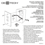
Figure 1: Pro 24” & 27” Wall Hoods
30”, 36”, 42”, 48”, 54”
(762, 914, 1067, 129, 1372mm)
18” (457mm)
24”, 27”
(61mm, 686mm)
12”
(305
mm)
BLOWER SKU CFM
VOLTAGE
(AC)
BLOWER
CURRENT
(AMPS)
CIRCUIT
BREAKER
(AMPS)
REMOTE BLOWER 600 CFM VTR630D 600 120 4.2 15
REMOTE BLOWER 1000 CFM VTR1030D 1000 120 5.7 15
REMOTE BLOWER 1300 CFM VTR1330E 1300 120 8.5 20* / 15**
INLINE BLOWER 600 CFM VTI610D 600 120 4.2 15
INLINE BLOWER 1000 CFM VTI1010D 1000 120 5.7 15
INTEGRAL BLOWER 600 CFM VTN630C 600 120 2.7 15
INTEGRAL BLOWER 1000 CFM VTN1030C 1000 120 5.4 15
Table 1: Blower & Circuit Breaker Ratings
* 20 Amp circuit breaker required when using the VTR1330E Remote Blower with a 27” Pro Wall Hood.
** 15 Amp circuit breaker required when using the VTR1330E Remote Blower with a 24” Pro Wall Hood.
When connected to a GFCI-protected supply, the Pro Hoods are suitable for use in damp locations that are protected from
outside weather conditions and not subject to saturation with water and other liquids, but can be subject to moderate
degrees of moisture. Refer to local codes, NEC/CEC, and or the Authority Having Jurisdiction (AHJ) for additional
information.

English 2
Safety Instructions
Important Safety Instructions
READ AND SAVE THESE INSTRUCTIONS
APPROVED FOR ALL RESIDENTIAL APPLIANCES
FOR RESIDENTIAL USE ONLY
Before you Begin
IMPORTANT: Save these Instructions for the Local Gas
Inspector’s use.
INSTALLER: Please leave these Instructions with this unit
for the owner.
OWNER: Please retain these instructions for future
reference.
WARNING:
If the information in this manual is not followed
exactly, fire or shock may result causing property
damage or personal injury.
Do not repair or replace any part of the appliance
unless specifically recommended in the
manuals. Improper installation, service or
maintenance can cause injury or property
damage or void product warranty. Refer to this
manual for guidance. All other servicing should
be done by a qualified technician.
CAUTION:
The unit is heavy and should be handled
accordingly. Proper safety equipment such as
gloves and adequate manpower of at least two
people must be used in moving the hood to avoid
injury and to avoid damage to the unit or the
floor. Rings, watches, and any other loose items
that may damage the unit or otherwise might
become entangled with the unit should be
removed.
Hidden surfaces may have sharp edges. Use
caution when reaching behind or under
appliance.
This appliance complies with one or more of the following
Standards:
• UL 858, Standard for the Safety of Household Electric
Ranges
• UL 923, Standard for the Safety of Microwave Cooking
Appliances
• UL 507, Standard for the Safety of Electrical Fans
• ANSI Z21.1- American National Standard for
Household Cooking Gas Appliances
• CAN/CSA-C22.2 No. 113, Fans and Ventilators
• CAN/CSA-C22.2 No. 61, Household Cooking Ranges
It is the responsibility of the owner and installer to
determine if additional requirements and/or standards
apply to specific installations. Always refer to local codes to
ensure all requirements are met.
SAFETY WARNING:
Turn off power circuit at service panel and lock
out panel before wiring this appliance.
Requirement: 120 VAC, 60 Hz 20 A. Allow the
appliance to cool after the power has been
turned off before servicing the appliance.
WARNING:
To reduce the risk of fire use only metal
ductwork.
If required by the National Electrical Code (or Canadian
Electrical Code), this appliance must be installed on a
separate branch circuit.
Installer — show the owner the location of the circuit
breaker or fuse. Mark it for easy reference.
Remove all tape and packaging before using the
appliance. After unpacking the appliance, please
recycle the packaging material as all
THERMADOR
®
appliance packaging is
recyclable. Never allow children to play with
packaging material.
Never modify or alter the construction of the appliance. For
example, do not remove panels or wire covers.

English 3
Grounding Instructions:
This appliance must be grounded. In the event of an
electrical short circuit, grounding reduces the risk of electric
shock by providing an escape wire for the electric current.
Be sure your appliance is properly installed and grounded
by a qualified technician. Installation, electrical connections
and grounding must comply with all applicable codes.
WARNING:
Do not use an extension cord. Improper
grounding can result in a risk of electric shock.
Consult a qualified electrician if the grounding
instructions are not completely understood, or if
doubt exists as to whether the appliance is
properly grounded. If the power cord is too short,
have a qualified electrician install an outlet near
the appliance.
To reduce the risk of fire or electric shock, do not use this
fan with any solid-state speed control devices.
TO REDUCE THE RISK OF FIRE, ELECTRIC SHOCK
AND INJURY TO PERSONS OBSERVE THE
FOLLOWING:
1. This ventilator assembly must be installed with
THERMADOR
®
recommended blowers only. Contact
Customer Service for additional options.
2. Use this unit only in the manner intended by the
manufacturer. If you have questions, contact the
THERMADOR
®
Customer Service at
1-800-735-4328.
3. Before servicing or cleaning unit, switch power OFF at
service panel and lock the service disconnecting
means to prevent power from being switched on
accidentally. When the service disconnecting means
cannot be locked, securely fasten a prominent warning
device, such as a tag, to the service panel.
4. Installation work and electrical wiring must be done by
qualified person(s) in accordance with all applicable
codes and standards, including fire-rated construction.
5. Sufficient air is needed for proper combustion and
exhausting of gases through the flue (chimney) of fuel
burning equipment to prevent back drafting. Follow the
heating equipment manufacturer's guideline and safety
standards such as those published by the National Fire
Protection Association (NFPA), The American Society
for Heating, Refrigeration and Air Conditioning
Engineers (ASHRAE), and the local code authorities.
6. When cutting or drilling into wall or ceiling, be careful
not to damage electrical wiring and other hidden
utilities.
7. Ducted fans must always be vented to the outdoors.
8. To properly exhaust air, be sure to duct air outside. Do
not vent exhaust air into spaces within walls, ceilings,
attics, crawl spaces or garages.
9. Before you plug in an electrical cord, be sure all
controls are in the OFF position.
WARNING:
Lamp holder might be hot. Disconnect from
power before servicing. Allow unit to cool after
the power has been turned off before servicing.
WARNING:
Local building codes may require the use of
make-up air systems when using ducted
ventilation systems greater than specified CFM
of air movement. The specified CFM varies from
locale to locale. Consult your HVAC professional
for specific requirements in your area.
CAUTION:
For general ventilating use only. DO NOT use to
exhaust hazardous or explosive materials or
vapors.
Vent unit to the outside of building only.

English 4
Installation
NOTE: Do not throw away any packaging until appliance is fully installed.
Parts Included
(1) Metal Transition with backdraft
damper
(2, 3, or 4 depending on model and size)
Stainless steel baffle filters
(2) Side panels
(1) Grease tray
(1) Remote blower adaptor
(2) 175W Heat lamps (on some models)
Halogen bulbs, installed
(1) Wooden bracket used for Hood
Mounting Bracket (part of install- do not
throw away)
(1) Fastener assortment
Use & Care Manual, Installation Instructions, and
Registration Card
Parts Not Included
Aluminum tape (DO NOT use duct tape)
1/2” (13mm) Conduit (if required, follow local codes)
Strain Relief
Blower
Optional duct cover accessory is available for separate
purchase. Refer to www.thermador.com for more details.
Optional Keep Hot Shelf accessory is available for
separate purchase. Refer to www.thermador.com for
more details.
Optional Backsplash accessory is available for separate
purchase. Refer to www.thermador.com for more details.
Tools Required
Flat head and phillips
screwdrivers
Wire stripper
Drill 3/16” (4.76mm) drill bit
3/8” (9.52mm) nut driver or
socket and ratchet
Protective work gloves
Considerations Before Installing Hood

English 5
1. For the most efficient air flow exhaust, use a straight
run or as few elbows as possible.
2. Do not use flex ducting.
3. COLD WEATHER installations should have an
additional backdraft damper installed to minimize
backward cold air flow and a non-metallic thermal
break to minimize conduction of outside temperatures
as part of the ductwork. The damper should be on the
cold air side of the thermal break. The break should be
as close as possible to where the ducting enters the
heated portion of the house.
4. Hood installation height above a cooktop or range can
vary. To obtain the necessary installation height above
a THERMADOR PROFESSIONAL
®
Cooktop or
Range, consult the appliance's installation manual.
* For indoor grill installations, THERMADOR
®
recommends a minimum of 36" (914mm)
clearance and remote and inline blowers only.
5. Remote blowers require a five wire installation.
6. Make-Up Air: Local building codes may require the
use of make-up air systems when using ducted
ventilation systems greater than specified CFM of air
movement. The specified CFM varies from locale to
locale. Consult your HVAC professional for specific
requirements in your area.
Appliance Installation
CAUTION:
Vent unit to the outside of building only. This unit
is only designed to be vented outside. It should
not be used for recirculation mode.
The hood can be mounted on a wall or suspended from a
cabinet. Both vertical and horizontal discharge are possible
with either mounting method.
Note:
Before installing the hood, the backsplash should be
installed first, if applicable.
Discharge Direction:
The hood is shipped ready for vertical discharge. To
change to horizontal discharge, move the discharge cover
shown in Figure 2 to the top of the hood. The plate is held
in place by (4) screws.
Figure 2: 24” & 27" Pro Wall Hood Models
Figure 3: Transition Cutout
This opening is
covered for
horizontal
discharge
This opening is
covered for
vertical discharge
21
3
/
4
” (552mm)
1
1
1
/
16
” (43mm)
4
1
/
4
”
(108mm)

English 6
Assembly of the Transition:
The supplied transition mounts to the top or rear of the
hood depending on the discharge direction.
1. A minimum height clearance of 6” (152mm) is needed
above the hood for transition mounting.
2. Align mounting holes at base of transition with the
mounting holes of the 1/2” (13mm) flange located at
the top or rear of the hood, depending on direction of
discharge (see Figure 2 on page 5).
3. Fasten transition to hood using (2) sheet metal screws
included with hood (see Figure 3 and Figure 4).
4. Seal connection between transition and hood with
aluminum tape.
5. Remove tape holding damper closed.
See Figure 1 on page 1 for overall hood dimensions.
Wall Mount Installation
Figure 5 shows a typical installation of the hood with a duct
cover. Accessory 6” (152mm) and/or 12” (305mm) duct
covers are used to fill the space between the hood and
ceiling (available for purchase separately).
The installation height ranges from a minimum height of 30”
(762mm) to a maximum height of 40” (1016mm); however,
it is necessary to follow the cooking appliance manufac-
turer’s installation instructions for proper hood height. In
Figure 5 one 6" (152mm) duct cover has been used in this
installation. Add or subtract duct covers as appropriate to
accommodate ceiling height and recommended hood
height. The duct cover structure is supported by the hood.
NOTICE:
The hood could incur some damage from heat if a
Professional Series Range or Cooktop is operated with
multiple burners at high settings under a hood that is
installed at minimum clearances.
Figure 4: Transition Connection
17
1
/
2
” (445mm)
10” (254mm)
Duct
3
5
/
16
”
(84mm)
Sheet metal screw
location (x2)
Figure 5: Typical Hood Installation
6” (152mm)
Duct Cover
18”
24”
(
610mm)
(457mm)
Note:
Follow cooking
recommendations
manufacturer’s
appliance
Hood Mounting Heights
Min 30” (762mm)
Max 40” (1016mm)

English 7
1. After the hood installation height has been determined,
draw a horizontal line at a distance above the cooktop
equal to the recommended hood installation height
plus 15
1
/
2
” (394mm). This line is the mounting location
of the wooden bracket shipped with the hood.
2. Find the centerline of the hood. Draw a vertical line
along this centerline up to the horizontal line drawn in
Step 1.
3. The hood is mounted to the wall using the wooden
bracket shipped with the hood. Remove the wooden
bracket located at the top side of the hood by removing
the two shipping screws. Mark the center line of the
wood bracket.
4. Locate a stud on both sides of the hood centerline to
use for mounting the wooden bracket as shown in
Figure 6.
5. Align the top of the wood bracket along the horizontal
line drawn in Step 1. Align the centerlines of the
bracket and cooktop.
6. Drill a 3” (76mm) deep 3/16” (3mm) tap hole through
the wooden bracket, wall, and into the stud.
7. Use (2) or (3), depending on model, 3” (76mm) screws
to attach the bracket to the wall as shown in Figure 7.
For support of longer hoods, use three studs.
Countersink the screw heads to prevent interference
with the hood.
8. On the wood bracket, mark the locations used to hang
the hood according to Figure 7.
9. Drill a 3/16” (4.8mm) tap hole through the wooden
bracket and wall. These 5/8” (16mm) screws do not
need to go into the studs.
Figure 6: Mounting the Wooden Bracket
Wall
Hood
Centerline
Wall
Studs
Recommended
Hood Height
+15
1
/
2
” (394mm)
To Cooking Surface
Height
Above
Cooktop
Screws
2 ea
3”
(76mm)
W
ooden Bracket
2
1
/
2
” (64mm)
Figure 7: Hanging the Hood
HOOD SIZE A
30” (762mm) 13” (330mm)
36” (914mm) 16” (406mm)
42” (1067mm) 19” (483mm)
48” (1219mm) 22” (559mm)
54” (1372mm) 25” (635mm)
Wall
Cooktop
Centerline
Screws
2 ea
3”
(76.2mm)

English 8
10. Use (2) 5/8” (16mm) screws to secure the wood
bracket leaving 1/4” (6mm) of each screw exposed for
hanging the hood.
Note:
Dashed line indicates cutout needed for clearance of the
transition (Figure 9).
Discharge Direction: Horizontal discharge requires a wall
cutout, as shown in Figure 9, to provide clearance for the
transition. The location of the cutout is determined by the
hood installation height.The transition supplied with the
hood connects to standard 10” (254mm) round duct.
Figure 11 shows the hood configured for vertical discharge.
Installations using this method require a cutout in the
ceiling to accommodate 10" (254mm) duct and the 1/2”
(13mm) conduit carrying power to the unit.
Duct covers, sold separately, are available to cover the
space between the top of the hood and ceiling (see
Figure 13).
Figure 8: Transition and Conduit Locations
Figure 9: Cutout Dimensions
1
1
/
8
”
(29mm)
3
3
/
16
”
2
3
/
8
”
1
7
/
8
”
7
7
/
8
”
2
3
/
8
”
(81mm)
(200mm)
(60mm)
(60mm)
(48mm)
5/8” (.16mm)
DIA clearance
holes for 1/2”
(12.7mm) conduit to
Note:
This figure depicts transition and conduit
locations only. See Figure 3 & Figure 4 on page 5
for overall hood dimensions.
junction box
Cooktop
Centerline
Base of
Hood
Location
23” (584mm)
2
3
/
4
”
(69mm)
12
1
/
2
”
(318mm)
Wall
Figure 10: Transition Centerline for Horizontal Discharge
Figure 11: Transition Centerline for Vertical Discharge
10
1
/
4
” (260mm)
10
1
/
2
”
(267mm)
Transition
Centerline
Wall
10
1
/
4
”
(260mm)
18”
(457mm)
5
13
/
16
”
(148mm)

English 9
11. Remove circular knockouts.
12. Remove junction box channel covering the wires (see
Figure 16 and Figure 17).
13. Before hanging hood, install transition per Figure 10 or
Figure 11. Fasten transition with (2) screws (3/8” sheet
metal, supplied) and aluminum tape per all applicable
codes.
Note:
Screws must not hinder damper operation.
14. Using two people to lift, rest the hood on the screws in
the wood bracket. Use the keyholes labeled "I" in
Figure 12. Make sure the wood bracket fits into the
recess on the back of the hood.
15. Tighten the screws in keyholes. Check hood levelness
and adjust if necessary.
16. From inside the hood, drive 5/8” (16mm) screws
through holes in hood into wooden bracket. See holes
labeled “J” in Figure 12.
17. Connect additional ducting.
Assembly & Installation Duct
Covers
(optional)
Optional duct covers shown in Figure 13 may be used to fill
the space between the hood and ceiling in wall mount
installations. 6" (152mm) and 12" (305mm) high duct
covers are available and may be ordered separately (see
“Parts Not Included” on page 4.)
1. If multiple duct covers are used, connect the pieces
together using sheet metal screws provided with the
duct cover accessories.
2. Attach the duct cover(s) to the hood using sheet metal
screws as shown in Figure 13.
3. From inside of hood, insert 5/8” (16mm) screws
supplied through holes labeled “L,” (1) on each side
and (4) along the front, into bottom of the cover.
Figure 12: Location of Screw Keyholes
I
I
J
Figure 13: Attachment of Duct Cover(s) to Hood
L
L
L
3/8” (9.52mm)
(quantity
dependent on
screw size)

English 10
Cabinet Installation
The hood can be installed under a cabinet by supporting
the hood from the top.
Note:
The cabinet must be structurally joined to the wall studs to
support the weight of this hood.
Figure 14 shows the (4) screw holes labeled “K” used for
mounting the hood to the bottom of the cabinet. Make sure
both knockouts have been removed.
1. In the base of the cabinet, drill 1/8” (3mm) tap holes
(Dimension A in Figure 14 and in Table 2,). Screw in
(4) 1" (25mm) screws (provided with hood) leaving 1/4”
(6mm) exposed to hang hood on.
2. If the hood is installed for vertical discharge, use
Figure 14 to create clearance holes for passage of the
transition and conduit (see Dimension B in Figure 8
and in Table 2 on the current page).
3. For horizontal discharge, use Figure 9 on page 8 for
the geometry of the cutout required for clearance of the
transition.
4. Hang hood from screws and tighten securely.
5. From inside of hood, insert screws supplied. Drill
through holes, use 5/8” (16mm) screws supplied, (1) on
each side and (4) along the front, into bottom of the
cabinet. See screw holes labeled "L" in Figure 14.
Blower Installation
All hoods require the choice of a Remote (Figure 20 on
page 13), Integral (Figure 18 on page 12), or Inline Blower
(Figure 22 on page 14). Use only THERMADOR
®
blowers
with THERMADOR
®
ventilation hoods. All blower models
are sold separately. See page 1 for recommended blowers
and for max current ratings.
1. The blower is attached to the hood using weld studs
provided on the mounting plate.
2. Figure 15 shows the weld studs in location B for
horizontal (rear) discharge. Attach (4) nuts (included
with hood) to the weld studs. For vertical discharge,
attach nuts to studs at the top of the mounting plate.
3. Guide the motor mounting plate over the studs and
tighten nuts to secure the blower to the hood.
Figure 14: Tap Hole and Screw Hole Locations
A
L
K
L
L
Tap Hole Locations
K
7
1
/
16
”
(17mm)
1
9
/
16
”
(40mm)
23”
(584mm)
Note:
This figure
depicts tap hole
and screw hole locations only. See
Figure 1 on page 1, for overall
hood dimensions.
HOOD
SIZE
A (Fig 13)
Tap Holes
B (Fig 7)
Conduit Holes
30” (762mm) 29” (736mm) 13” (330mm)
36” (914mm) 35” (889mm) 16” (406mm)
42” (1067mm) 41” (1041mm) 19” (483mm)
48” (1219mm) 47” (1194mm) 22” (559mm)
54” (1372mm) 53” (1346mm) 25” (635mm)
Table 2: Centerline Hole Dimensions for Figure 14 & Figure 8
Figure 15: Weld Stud Locations
B
B

English 11
Wire Routing Instruction
Vertical Discharge
Install wire cover per Figure 16. The PH30HS model does
not need a wire cover.
Horizontal Discharge
Install wire cover per Figure 17. The PH30HS and GS
models do not need a wire cover.
WARNING:
Turn off electricity at the service panel before
wiring the unit. (See “Safety Instructions” on
page 2.)
Figure 16: Vertical Discharge
Figure 17: Horizontal Discharge

English 12
Wiring the Hood with an
Integral Blower
1. Integral Blower models VTN630C and VTN1030C are
designed to work with the PH hoods and are sold
separately.
2. Remove the junction box cover.
3. Connect the blower’s Molex plug connector to the
connector present inside the hood as shown in
Figure 19.
4. Install 1/2” (13mm) conduit connector in junction box.
5. Run black, white, and green wires (#12 AWG) in 1/2”
(13mm) conduit from power supply to junction box.
6. Connect the power supply wires to the hood wires in
the following order: black to black, white to white, and
green wire to green ground screw on chassis. Use
spring type wire nuts supplied. (Lost or missing wire
nuts should only be replaced with: Spring type wire
nuts rated for a minimum of (2) # 18ga wires and
maximum of (4) #14ga wires, UL & CSA rated to 600V
and 302° F/ 150° C.)
7. Close junction box cover. Check to see that light bulbs
are secure in their sockets. Install filters (“Installing
Filters, Grease Trays, and Heat Lamps” on page 15).
Turn power on at service panel. Check operation of the
hood.
Figure 18: Integral Blower
Figure 19: Wiring the Hood with an Integral Blower
25”
(635mm)
6
7
/
8
”
(175mm)
6
3
/
4
”
(171mm)
2
1
/
4
”
(57mm)
4
1
/
8
”
(105mm)
8
1
/
4
”
(210mm)
8
7
/
8
”
(225mm)
From Control Panel
From Blower

English 13
Wiring the Hood with a
Remote Blower
Both Pro 24" Wall Hood and Pro 27" Wall Hood models can
be installed with remote blowers (Figure 20). For
installation instructions see the instructions supplied with
the blower unit.
1. Remove the junction box cover.
2. Install 1/2” (13mm) conduit connectors.
3. Run black, white, and green wires (#12 AWG) in 1/2”
(13mm) conduit from power supply to junction box.
4. Connect the power supply wires to the hood wires in
the following order: black to black, white to white, and
green wire to green ground screw on chassis. Use
spring type wire nuts supplied. (Lost or missing wire
nuts should only be replaced with: Spring type wire
nuts, rated for a minimum of (2) # 18ga wires and
maximum of (4) #14ga wires, UL & CSA rated to 600V
and 302° F/ 150° C).
5. Connect the “pigtail” to the connector inside the
junction box.
6. Run (5) wires (#14 AWG) in 1/2” (13mm) conduit from
the remote blower to the second conduit connector.
7. Connect the remote blower to the pigtail wires (Step 6)
as per Figure 21. Connect the remote blower green
(ground) wire to the ground screw in the junction box.
Refer to the blower installation instructions for further
wiring details.
8. Close junction box cover. Check that all light bulbs are
secure in their sockets. Install filters (“Installing Filters,
Grease Trays, and Heat Lamps” on page 15). Turn
power on at service panel, and check lights and blower
operation per Use & Care Manual.
Figure 20: Remote Blower
Figure 21: Wiring the Hood with a Remote Blower
13
5
/
8
”
(346mm)
2
1
/
8
”
12
1
/
8
”
(308mm
)
(54mm)
2
1
/
8
”
(54mm)
19
7
/
8
”
(505mm)
(349mm)
13
3
/
4
”
10”
(254mm)
6
1
/
2
”
(165mm)
1
7
/
8
”
(48mm)
12
7
/
8
”
(327mm)
9
7
/
8
”
(251mm)

English 14
Wiring the Hood with an Inline
Blower
1. Remove the junction box cover.
2. Install 1/2” (13mm) conduit connectors.
3. Run black, white, and green wires (#12 AWG) in 1/2”
(13mm) conduit from power supply to junction box.
4. Connect the power supply wires to the hood wires in
the following order: black to black, white to white, and
green wire to green ground screw on chassis. Use
spring type wire nuts supplied. (Lost or missing wire
nuts should only be replaced with: Spring type wire
nuts, rated for a minimum of (2) # 18ga wires and
maximum of (4) #14ga wires, UL & CSA rated to 600V
and 302° F/ 150° C).
5. Connect the “pigtail” to the connector inside the
junction box.
6. Run (5) wires (#14 AWG) in 1/2” (13mm) conduit from
the inline blower to the second conduit connector.
7. Connect the inline blower to the pigtail wires (Step 6)
as per Figure 23. Connect the inline blower green
(ground) wire to the ground screw in the junction box.
8. Close junction box cover. Check that all light bulbs are
secure in their sockets. Install filters (“Installing Filters,
Grease Trays, and Heat Lamps” on page 15). Turn
power on at service panel, and check lights and blower
operation per Use & Care Manual.
Figure 22: Inline Blower
Figure 23: Wiring the Hood with an Inline Blower
12
7
/
8
”
(327mm)
9
7
/
8
”
(251mm)
12
7
/
8
”
(327mm)
14
3
/
8
”
(365mm)
12”
(305mm)
19
1
/
8
”
(486mm)
7
/
8
“(22mm)
7
/
8
”
(22mm)

English 15
Installing Filters, Grease Trays, and Heat Lamps
• Remove all plastic from hood pieces.
• Insert in the following order:
1) Grease Tray — Push up and in over the rear lip.
2) Filters —
Slide filter over the front lip. Push filter
rear up, then slide back over rear lip.
3) Side Panels — Insert these the same way as the
filters.
Reverse the above directions to remove the grease tray, fil-
ters and side panels (Figure 24).
Note:
Depending upon the size and model of hood, there will be
from 1 to 3 filters per hood.
Note:
Do not use cooktop while hood is disassembled. Grease
trays must be in place before installing the filters.
Heat Lamp Replacement (some models)
• Turn heat lamp clockwise to install (Figure 25).
• Replace lamp with either a PAR-38 175W heat lamp or
a PAR-40 250W heat lamp.
The PAR-38 175W heat lamp provides a tighter seal within
the enclosure and produces the same amount of effective
heat with lower energy consumption. These lamps may not
be readily available at local retail outlets. The PAR-40
250W heat lamp is more widely available. It can be used
instead.
PAR-38 175W heat lamps can be purchased through the
following retailers:
• OpTech Inc: 800-848-6624 or
www.optechlightbulbs.com
• bulbs.com: 888-455-2800 or www.bulbs.com
Figure 24: Filter Installation
1
1
2
2
Filters
Grease Tray
Side
panel
Side
panel
Figure 25: Heat Lamp Replacement

Introduction . . . . . . . . . . . . . . . . . . . . . . . . . . . . . . . . . . . . . . . . . . . . . . . . . . . . 1
Consignes de sécurité . . . . . . . . . . . . . . . . . . . . . . . . . . . . . . . . . . . . . . . . . . . 2
A
vant de commencer . . . . . . . . . . . . . . . . . . . . . . . . . . . . . . . . . . . . . . . . . . . . . 2
Installation . . . . . . . . . . . . . . . . . . . . . . . . . . . . . . . . . . . . . . . . . . . . . . . . . . . . . 4
Facteurs à prendre en compte avant d’installer la hotte . . . . . . . . . . . . . . . . . . . 4
Installation de l’appareil . . . . . . . . . . . . . . . . . . . . . . . . . . . . . . . . . . . . . . . . . . . 5
A
ssemblage du raccord . . . . . . . . . . . . . . . . . . . . . . . . . . . . . . . . . . . . . . . . . . . 6
Installation murale . . . . . . . . . . . . . . . . . . . . . . . . . . . . . . . . . . . . . . . . . . . . . . . 6
A
ssemblage et installation des recouvrements de conduit . . . . . . . . . . . . . . . . . 9
Installation à une armoire . . . . . . . . . . . . . . . . . . . . . . . . . . . . . . . . . . . . . . . . . .10
Installation du ventilateur . . . . . . . . . . . . . . . . . . . . . . . . . . . . . . . . . . . . . . . . . 10
Instructions pour le trajet des câbles . . . . . . . . . . . . . . . . . . . . . . . . . . . . . . .11
Débouché vertical . . . . . . . . . . . . . . . . . . . . . . . . . . . . . . . . . . . . . . . . . . . . . . . .11
Débouché horizontal . . . . . . . . . . . . . . . . . . . . . . . . . . . . . . . . . . . . . . . . . . . . . .11
Câblage de la hotte avec un ventilateur intégré . . . . . . . . . . . . . . . . . . . . . . . . .12
Câblage de la hotte avec un ventilateur à distance . . . . . . . . . . . . . . . . . . . . . .13
Câblage de la hotte avec un ventilateur de conduit. . . . . . . . . . . . . . . . . . . . . . .14
Installation des filtres, des plateaux à graisse et des lampes infrarouges . . . . .15
Cet appareil électroménager de THERMADOR
mc
est fait par
BSH Home Appliances Corporation
5551 McFadden Ave.
Huntington Beach, CA 92649
Des questions?
1-800-735-4328
www.thermador.com
Nous attendons de vos nouvelles!
Table de matières

Française 1
Introduction
Ce manuel fournit des instructions pour l’installation
adéquate de deux types de hottes murales
PROFESSIONAL
mc
de THERMADOR :
• Modèles de hotte murale Pro de 27 po (PHxxGS) :
27 po (686 mm) de profondeur, largeurs de 36 po
(914 mm), 42 po (1067 mm), 48 po (1219 mm) et
54 po (1372 mm). Les modèles de cette série se
caractérisent par leur pavillon en acier inoxydable
brossé, des lampes halogènes et des lampes
infrarouges (voir Figure 1).
• Modèles de hotte murale de 24 po (PHxxHS) :
24 po (610 mm) de profondeur, largeurs de 30 po
(76 2mm), 36 po (914 mm) et 48 po (1219 mm).
Les modèles de cette série se caractérisent par
leur pavillon en acier inoxydable brossé et des
lampes halogènes (voir Figure 1).
Toutes les hottes doivent être installées avec un ventilateur
à distance, un ventilateur de conduit ou un ventilateur
intégré. N’utilisez que les ventilateurs THERMADOR
mc
avec les hottes THERMADOR
mc
. Tous les modèles de
ventilateur sont vendus séparément. Consultez le
Tableau 1 – caractéristiques assignées du ventilateur et du
disjoncteur – pour connaître les modèles de ventilateurs
recommandés. Communiquez avec le service à la clientèle
pour d’autres options.
Tous les modèles de hottes sont de régime 120 VCA.
Consultez le Tableau 1 pour les caractéristiques assignées
du disjoncteur.
Figure 1: Hottes murales Pro de 24 po et 27 po
30, 36, 42, 48, 54 PO
(762, 914, 1067, 129, 1372mm)
18
PO
(457mm)
24 PO, 27 PO
(61mm, 686mm)
12 po
(305
mm)
VENTILATEUR
No
d’article
pi
3
/min
TENSION
(CA)
Courant du
ventilateur
(ampères)
Disjoncteur
(ampères)
VENTILATEUR À DISTANCE 600 pi
3
/min
VTR630D 600 120 4.2 15
VENTILATEUR À DISTANCE 1000 pi
3
/min
VTR1030D 1000 120 5.7 15
VENTILATEUR À DISTANCE 1300 pi
3
/min
VTR1330E 1300 120 8.5 20* / 15**
VENTILATEUR DE CONDUIT 600 pi
3
/min
VTI610D 600 120 4.2 15
VENTILATEUR DE CONDUIT 1000 pi
3
/min
VTI1010D 1000 120 5.7 15
VENTILATEUR INTÉGRÉ 600 pi
3
/min
VTN630C 600 120 2.7 15
VENTILATEUR INTÉGRÉ 1000 pi
3
/min
VTN1030C 1000 120 5.4 15
Table 1: Caractéristiques assignées du ventilateur et du disjoncteur
* Disjoncteur de 20 ampères requis lors de l’utilisation d’un ventilateur à distance VTR1330E avec une hotte Pro Wall de 27 po.
** Disjoncteur de 15 ampères requis lors de l’utilisation d’un ventilateur à distance VTR1330E avec une hotte Pro Wall de 24 po.
Lorsqu’elles sont protégées par un
disjoncteur de fuite à la terre, les hottes Pro peuvent être utilisées dans des endroits humides à l’abri
des conditions météorologiques extérieures et de saturations par de l’eau et d’autres liquides, quoiqu’elles puissent être soumises à un
certain degré d’humidité. Consultez les codes locaux, le Code national de l’électricité/Code canadien de l’électricité, et l’autorité
compétente pour obtenir de plus amples renseignements.

Française 2
Consignes de sécurité
Consignes de sécurité importantes
LISEZ ET CONSERVEZ CES INSTRUCTIONS
APPROUVÉES POUR TOUS LES ÉLECTROMÉNAGERS
POUR UTILISATION RÉSIDENTIELLE SEULEMENT
Avant de commencer
IMPORTANT : Conservez ces instructions pour
l’inspecteur de la société gazière de votre localité.
INSTALLATEUR : Veuillez laisser ces instructions
d’installation avec l’appareil pour le propriétaire.
PROPRIÉTAIRE : Veuillez conserver ces instructions pour
consultation ultérieure.
AVERTISSEMENT:
Si vous ne suivez pas rigoureusement les
renseignements fournis dans le présent manuel,
un incendie ou une décharge électrique pourrait
causer des dommages matériels ou des
blessures corporelles.
Ne réparez et ne remplacez aucune pièce de
l’appareil à moins que le manuel ne
recommande expressément de le faire.
L'installation, la réparation ou l'entretien
inadéquat de cet appareil peut causer des
blessures corporelles ou des dommages
matériels, ou encore annuler la garantie du
produit. Consultez le présent manuel pour
obtenir des conseils. Tous les autres travaux
d’entretien doivent être effectués par un
technicien qualifié.
ATTENTION:
La cuisinière est lourde et doit être manipulée en
conséquence. Pour éviter tout risque de blessure
ou de dommages à l’appareil ou au plancher, la
cuisinière devrait être déplacée par au moins
deux personnes utilisant de l’équipement
adéquat, comme des gants de protection, et ne
portant pas des bagues, des montres ou tout
autre objet semblable pouvant endommager
l’appareil ou s’y accrocher.
Les surfaces cachées de l’appareil peuvent
comporter des saillies coupantes. Faites
attention lorsque vous prenez l’appareil par le
dessous ou que vous le tirez.
Cet appareil est conforme à une ou plusieurs des normes
suivantes:
• UL 858 – norme visant la sécurité en matière de
cuisinières électriques domestiques
• UL 923 – norme visant la sécurité en matière
d’appareil de cuisson par micro-ondes
• UL 507 – norme visant la sécurité en matière de
ventilateurs électriques
• ANSI Z21.1 – norme américaine régissant les
appareils électroménagers de cuisson au gaz
• CAN/CSA-C22.2 No 113 – ventilateurs
• CAN/CSA-C22.2 No 61 – cuisinières domestiques
Il est de la responsabilité du propriétaire et de l’installateur
de déterminer les exigences ou les normes
supplémentaires pouvant s’appliquer à des installations
particulières. Consultez toujours les codes locaux pour
vous assurer que toutes les exigences sont respectées.
MISE EN GARDE DE SÉCURITÉ:
Coupez l’alimentation du disjoncteur et
verrouillez le panneau avant de procéder au
câblage de cet appareil. Exigence : 120 VCA,
60 Hz, 20 A. Avant de procéder à l’entretien de
l’appareil, laissez-lui le temps de refroidir une
fois que l’alimentation électrique est coupée.
ATTENTION:
Pour réduire les risques d’incendie, n’utilisez que
des conduits métalliques.
Si le Code national de l’électricité (ou le code canadien de
l’électricité) l’exige, cet appareil doit être installé sur un
circuit de dérivation séparé.
Installateur – montrez au propriétaire l’emplacement du
disjoncteur ou du fusible. Marquez-le pour qu’il soit facile à
identifier.
Enlevez tout le matériel d’emballage et le ruban
adhésif avant d’utiliser l’appareil. Veuillez
recycler le matériel d’emballage, car tout ce que
THERMADOR
mc
utilise pour emballer ses
appareils est recyclable. Ne laissez jamais des
enfants jouer avec le matériel d’emballage.
Ne modifiez jamais la construction de l’appareil. Par
exemple, n’enlevez pas de panneaux ou de couvre-fils.
/