Page is loading ...

INSTRUCTION MANUAL
取扱説明書
Fine Level Switch
KML502 Series
MKML Series
SM-A84885-A
• Read this Instruction Manual before using the product.
• Read the safety notes carefully.
• Keep this Instruction Manual in a safe and convenient place for future reference.

SM-A84885-A PREFACE
i 2023-10-26
PREFACE
Thank you for purchasing CKD's "KML502 Series/MKML Series" fine level switch.
This Instruction Manual contains basic matters such as installation and usage instructions in order to
ensure optimal performance of the product. Please read this Instruction Manual thoroughly and use the
product properly.
Keep this Instruction Manual in a safe place and be careful not to lose it.
Product specifications and appearances presented in this Instruction Manual are subject to change
without notice.
• The product is intended for users who have basic knowledge about materials, piping, electricity,
and mechanisms of pneumatic components. CKD shall not be responsible for accidents caused
by persons who selected or used the product without knowledge or sufficient training.
• Since there are a wide variety of customer applications, it is impossible for CKD to be aware of all
of them. Depending on the application or usage, the product may not be able to exercise its full
performance or an accident may occur due to fluid, piping, or other conditions. It is the
responsibility of the customer to check the product specifications and decide how the product shall
be used in accordance with the application and usage.

SM-A84885-A SAFETY INFORMATION
ii 2023-10-26
SAFETY INFORMATION
When designing and manufacturing any device incorporating the product, the manufacturer has an
obligation to ensure that the device is safe. To that end, make sure that the safety of the machine
mechanism of the device, the pneumatic or water control circuit, and the electric system that controls
such mechanism is ensured.
To ensure the safety of device design and control, observe organization standards, relevant laws and
regulations, which include the following:
ISO 4414, JIS B 8370, JFPS 2008 (the latest edition of each standard), the High Pressure Gas
Safety Act, the Industrial Safety and Health Act, other safety rules, organization standards, relevant
laws and regulations
In order to use our products safely, it is important to select, use, handle, and maintain the products
properly.
Observe the warnings and precautions described in this Instruction Manual to ensure device safety.
Although various safety measures have been adopted in the product, customer's improper handling
may lead to an accident. To avoid this:
Thoroughly read and understand this Instruction Manual
before using the product.
To explicitly indicate the severity and likelihood of a potential harm or damage, precautions are
classified into three categories: "DANGER", "WARNING", and "CAUTION".
DANGER
Indicates an imminent hazard. Improper handling will cause death or
serious injury to people.
WARNING
Indicates a potential hazard. Improper handling may cause death or serious
injury to people.
CAUTION
Indicates a potential hazard. Improper handling may cause injury to people
or damage to property.
Precautions classified as "CAUTION" may still lead to serious results depending on the situation.
All precautions are equally important and must be observed.
Other general precautions and tips on using the product are indicated by the following icon.
Indicates general precautions and tips on using the product.

SM-A84885-A SAFETY INFORMATION
iii 2023-10-26
Precautions on Product Use
WARNING
The product must be handled by a qualified person who has extensive knowledge and
experience.
The product is designed and manufactured as a device or part for general industrial machinery.
Use the product within the specifications.
The product must not be used beyond its specifications. Also, the product must not be modified
and additional work on the product must not be performed.
The product is intended for use in devices or parts for general industrial machinery. It is not
intended for use outdoors or in the conditions or environment listed below.
• In applications for nuclear power, railroad system, aviation, ship, vehicle, medical equipment,
and equipment that directly touches beverage or food.
• For special applications that require safety including amusement equipment, emergency shut-
off circuit, press machine, brake circuit, and safety measures.
• For applications where life or properties may be adversely affected and special safety
measures are required.
(Exception is made if the customer consults with CKD prior to use and understands the
specifications of the product. However, even in that case, safety measures must be taken to
avoid danger in case of a possible failure.)
Do not handle the product or remove pipes and devices until confirming safety.
• Inspect and service the machine and devices after confirming the safety of the entire system.
Also, turn off the energy source (air supply or water supply) and power to the relevant facility.
Release compressed air and fluid from the system and use extreme care to avoid water or
electric leakage.
• Since there may be hot or live parts even after operation has stopped, use extreme care when
handling the product or removing pipes and devices.
• When starting or restarting a machine or device that incorporates pneumatic components,
make sure that a safety measure (such as a pop-out prevention mechanism) is in place and
system safety is secured.

SM-A84885-A SAFETY INFORMATION
iv 2023-10-26
Precautions on Design and Selection
WARNING
It is the customer's responsibility to check the specifications of this product and its
compatibility with the customer's system before selecting and handling the equipment.
Incorrect equipment selection and handling may cause not only problems with this product but
also problems with your system.
Set the temperature, pressure and other use conditions in accordance with the specification
range of the product.
To prevent backflow of the detection liquid and false detection, observe the following
precautions regarding the installation environment.
• Please install and use under atmospheric pressure environment.
It cannot be used for detection in sealed liquid tanks or similar liquid tanks.
• Do not install the product in a chemical atmosphere or in an atmosphere that may damage the
switch contacts.
* Examples of hazardous atmospheres: dust, organic silicon materials, hydrofluoric acid, etc.
*If the microswitch type is used in an atmosphere of siloxic acid generated from organic silicon,
contact failure may occur.
• Install at a position higher than the upper limit of the liquid tank to be detected.
• Install with the micro switch/reed switch facing up.
• When using a reed switch type, do not bring magnetic components (magnets, solenoid valves,
etc.) near the product.
• Install it in a location that is not easily affected by noise.
CAUTION
Cautions regarding signal processing
The ON-OFF signal may be repeatedly output (chattering) depending on the fluctuation of the
liquid level and working conditions. Take countermeasures against chattering by using a timer on
the control side, etc.
Precautions for switching water level
The switching water level listed in catalogs, etc. is the value for water, and changes depending on
the specific gravity of the detection solution.
Precautions on Product Disposal
CAUTION
When disposing of the product, comply with laws pertaining to disposal and cleaning of
wastes and have an industrial waste disposal company dispose of the product.

SM-A84885-A CONTENTS
v 2023-10-26
CONTENTS
PREFACE ........................................................................................................................... i
SAFETY INFORMATION .................................................................................................. ii
Precautions on Product Use .......................................................................................... iii
Precautions on Design and Selection ........................................................................... iv
Precautions on Product Disposal .................................................................................. iv
CONTENTS ....................................................................................................................... v
1. PRODUCT OVERVIEW ............................................................................................. 1
1.1 Product Overview................................................................................................ 1
1.2 Part Name ........................................................................................................... 1
1.3 Model Number Indication .................................................................................... 2
1.4 Dimensions ......................................................................................................... 3
1.5 Specifications ...................................................................................................... 4
1.6 Description of Operation ..................................................................................... 4
2. INSTALLATION ......................................................................................................... 5
2.1 Piping .................................................................................................................. 5
2.2 Wiring .................................................................................................................. 5
3. USAGE ....................................................................................................................... 6
3.1 Safety Instructions .............................................................................................. 6
3.2 Supply pressure setting procedure ..................................................................... 7
3.3 Manifold station addition/replacement procedure .............................................. 8
4. TROUBLESHOOTING............................................................................................. 10
4.1 Problems, Causes, and Solutions .................................................................... 10
5. WARRANTY PROVISIONS ..................................................................................... 14
5.1 Warranty Conditions ......................................................................................... 14
5.2 Warranty Period ................................................................................................ 14
5.3 Remarks ............................................................................................................ 14

SM-A84885-A 1. PRODUCT OVERVIEW
1 2023-10-26
1. PRODUCT OVERVIEW
1.1 Product Overview
This product is a liquid level switch that detects the interface between air and liquid using compressed air
or nitrogen gas as a medium and outputs the contact.
1.2 Part Name
◼ Single unit
◼ Manifold
◼ Joiner set
Part name
Material
1
Switch
―
2
Switch cover
PPS
3
Body
PPS
4
Single plate
PPS
5
Fitting
Stainless steel
6
Housing
Nylon 66
7
Terminal
Brass, Tin plating
Internal
parts
Diaphragm
FKM、FFKM
Part name
Material
8
Supply block
PPS
9
Joiner set
PPS、FKM、Stainless steel
10
Manifold plate
PPS
Part name
Material
11
Hexagon socket head cap screw
Stainless steel
12
Joiner for front
PPS
13
Orifice collar
PPS、FKM
14
Joiner for rear (nut built-in)
PPS、Stainless steel
<Accessories>

SM-A84885-A 1. PRODUCT OVERVIEW
2 2023-10-26
1.3 Model Number Indication
◼ Single unit
◼ Manifold
◼ Joiner set
➊Sensing classification(Switching water level)
Symbol Description
18~12mm
21~3mm
➌Option
Symbol Description
Blank Single unit
-M Single unit with manifold plate
➋Switch
Symbol Description
AMicro switch (C contact)
BReed switch (A contact)
CReed switch (B contact)
➊Sensing classification(Switching water level)
Symbol Description
18~12mm
21~3mm
➌Number of manifolds
Symbol Description
11 stations
22 stations
33 stations
44 stations
55 stations
Model No.
❷Switch
➌Option
➊Sensing classification
(Switching water level)
Model No.
❷Switch
➌Number of manifolds
➊Sensing classification
(Switching water level)
➌Option

SM-A84885-A 1. PRODUCT OVERVIEW
3 2023-10-26
1.4 Dimensions
◼ Single unit
◼ Manifold
Station No.
A
B
C
D
1
―
66
76
52
2
36
102
112
88
3
72
138
148
124
4
108
174
184
160
5
144
270
220
196

SM-A84885-A 1. PRODUCT OVERVIEW
4 2023-10-26
1.5 Specifications
item
KML502-1D-*
KML502-2D-*
Supply gas
Working fluid
Compressed air/nitrogen gas (*1)
Working pressure
kPa
15 to 35
10 to 35
Operating fluid temp.
℃
5 to 60
Ambient temperature
℃
5 to 60
Pressure
resistance
P.S port
kPa
100
P.I port
kPa
10 (1000mm for detection fluid water)
6(600mm for detection fluid water)
Contact
capacitance
A-type
3A 125/250 VAC resistance load (micro switch)
B-type, C-type
0.25 A 100 VDC resistance load (reed switch)
Switching water level
mm
8 to 12 (*2)
1 to 3(*2)
Hysteresis
mm
2 (*2)
Repeatability
mm
±1 (*2)
Response time
ms
200 or less (working pressure 20kPa, ambient temperature 24°C,
detection tube inner diameter of ø4, length 5 m)
Detection tube I.D.
Φmm
4
Tube length
m
Within 5
Consumption flow rate
cm3/min(ANR)
750 or less (at working pressure 20 kPa)
Detection flow rate
cm3/min(ANR)
45±10 (at working pressure 20 kPa)
Weight
Kg
0.14
*1: Use fluid passed through a filter with a filtration degree of 0.3 μm or less.
*2: The above specifications are values obtained at working pressure 20 kPa (ambient temperature: 24±2°C).
Be sure to use working pressure with a high degree of cleanliness.
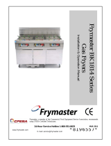
1.6 Description of Operation
1 The liquid level rises and the tip of the detection tube sinks below the liquid level.
2 A head pressure equal to the height of the liquid level at which the tip of the detection tube is
submerged is generated inside the detection tube.
3 The slight pressure change in the P.I port is amplified and the pressure inside the product
increases.
4 The internal diaphragm rises and pushes up the switch.
⑶The slight pressure change in
the P.I port is amplified and the
pressure inside the product
increases.
liquid
⑷The internal diaphragm rises
and pushes up the switch.
⑵A head pressure equal to the
height of the liquid level at
which the tip of the detection
tube is submerged is
generated inside the detection
tube.
⑴The liquid level rises and the tip of the
detection tube sinks below the liquid level.

SM-A84885-A 2. INSTALLATION
5 2023-10-26
2. INSTALLATION
2.1 Piping
CAUTION
Make sure there are no leaks or restrictions in the piping.
Four supply ports are provided on the manifold product supply block.
Please mask unused ports with the attached plugs.
As port cracking and screw damage may occur when constructing the manifold product
supply port, tighten with a torque of 0.4 to 0.6N・m with the resin fitting.
2.2 Wiring
Check the type of switch for the product you are using
and wire it with reference to the figure on the right.
Please refer to the specification table on page 4 for the
contact capacity.
CAUTION
Never perform wiring work while the power is energized (ON).
Check that there is no incorrect wiring before turning ON the power.
Use the supplied housing and terminals for wiring.
Do not solder the connection to the microswitch or reed switch.
Separate the wiring from the power lines of motors, heaters, etc.
KML502-*D-A
Micro switch
(C contact)
KML502-*D-B
Reed Switch
(A contact)
KML502-*D-C
Reed Switch
(B contact)

SM-A84885-A 3. USAGE
6 2023-10-26
3. USAGE
3.1 Safety Instructions
CAUTION
Precautions regarding supply gas
• Use a gas that has been filtered of dust and oil through a submicron filter/micro alescer.
• Use a low-pressure regulator with oil-free processing.
• Do not shut off the supply gas to prevent backflow of the chemical atmosphere or clogging of
the flow path due to crystallization of the chemical.
• When one regulator regulating pressure is branched to multiple KML products, make sure that
gas within the operating pressure range is supplied to each product.
• If pressure over 100 kPa is applied to the P.S port, the diaphragm may be damaged, and so
gradually raise the supply pressure from 0kPa.
Precautions regarding detection tubes
• Use the detection tube with an inner diameter of ø4 mm and a length of 5 m or less.
• Do not install filters, solenoid valves, or anything else that will cause resistance in the middle
of the sensing tube.
• The tip of the detection tube should be placed at least 2 mm above the bottom of the liquid
tank so that the nozzle is not blocked.
• Do not block the P.I port, EXH port or detection tube with hands. Otherwise, failures may be
caused.
Installation precautions of KML502-*D-*-M
• If increasing or replacing the number of stations using KML502-* D-*-M, perform as described
in the instruction manual.
When adding stations, prepare a separate joiner set (KML502-JC-SET).
Other precautions
• This product is adjusted at the time of shipment. If the Adjustment prohibited plate is removed
and the product is readjusted by the customer, performance is not guaranteed.

SM-A84885-A 3. USAGE
7 2023-10-26
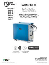
3.2 Supply pressure setting procedure
1 Please connect the piping using the air circuit shown below.
(Note) Before piping, adjust the set pressure of the two regulators to zero.
2 Adjust the regulator on the pressure source side so that the pressure displayed on the gauge is
100 kPa.
3 Next, use the regulator on the detector side to adjust the pressure just before the P.S port to the
rated value of 20 kPa (pressure range 10 to 35 kPa).
(Note)
Be careful not to let the pressure exceed the pressure range.
Please do not seal the P.I port.
If the water level depth is 1000 mm, please use the working pressure at 15 kPa or more.
4 With the above steps, the adjustment is complete and the specifications are satisfied.
Pneumatic
supply
Air dryer
Air filter
0.3 µm
Oil mist filter
Pressure gauge
100 kPa
Low pressure regulator
Pressure gauge
Rating 20 kPa
(10 to 35 kPa)
EXH
switching
water level
KML502
P.S
P.I

SM-A84885-A 3. USAGE
8 2023-10-26
3.3 Manifold station addition/replacement procedure
1 Remove the hexagon socket set screws from the joiner between the sensors and supply blocks
that you want to replace or add.
*Hex wrench size used: 2 mm (5/64: inch)
This is a replacement procedure for adding or replacing
[KML502-*D-*-M].
When increasing the number of stations, remove the
joiner screws between the sections to be increased.
When replacing a sensor, remove the joiner screws
on both sides of the sensor to be replaced.
Select the side for the joiner
(2 flat head hexagon socket head cap screws)
and the side for the joiner back.
An orifice collar is inserted inside.
2 To add more units, fit the joiner set [[KML502-JC-SET] rear side of the joiner into the manifold of
the sensor for expansion.
When replacing, insert the joiner rear, which is removed from both sides, into the grooves on both
sides.
Joiner for front
orifice collar
Flat head screw with
hexagon socket
Joiner for the rear
Joiner for the rear
Joiner for the rear *The square nut is facing backwards

SM-A84885-A 3. USAGE
9 2023-10-26
Included in joiner set
orifice collar
KML502-*D-*-M
Be careful of
dropping
items
3 When expanding stations, install the orifice guard on the manifold side surface where the orifice
guard is not installed. (Applying alcohol to the O-ring will make it easier to install.)
Be sure to insert the orifice collars on both sides.
Pinch the joiner so that the back side does not fall off.
4 When the temporary assembly is completed, tighten with the countersunk screws mounted for the
joiner surface.
(Recommended tightening torque: 0.5±0.05 N·m) * Tightening too strongly may cause damage.
5 After assembly, check that the manifold is assembled straight before use.
Pinch
Check that it is straight.
*If it is bent due to
improper assembly, it
may cause leakage.

SM-A84885-A 4. TROUBLESHOOTING
10 2023-10-26
4. TROUBLESHOOTING
4.1 Problems, Causes, and Solutions
If this product does not operate as intended, check the piping and wiring before inspecting the product a
s per the table below.
Malfunctioning
phenomenon
Cause
confir-
mation
Counter-
measures
The switch does not turn off
the output
When connecting or closing with a small inner diameter tube to the EXH port.
→Difficult to exhaust.
A
a
If the pressure on the tank side is higher than the pressure at the location where
the switch body is installed.
→Pressure difference is higher than the switching pressure.
B
b
If there is piping resistance between the P.I port and the detection nozzle.
→No bubbles are generated from the detection nozzle.
G
g
Does not output
When connecting a vacuum source to the EXH port.
→The switch does not work due to the structure.
A
a
When pressure is supplied exceeding the proof pressure.
→The diaphragm is damaged.
C
c
When clean supply gas is not supplied.
→The internal orifice is clogged with debris.
D
d
Loose piping/connections.
→Leakage occurs.
F
f
No electrical signal is output
If the contact capacity is exceeded.
→The switch is damaged.
E
e
flowed back
Pressure within the operating range is not supplied to each switch.
F
G
f
g
No air bubbles come out of the detection nozzle.
The set position of the switch is below the tank.
H
h
If you have any other questions or concerns, contact your nearest CKD sales office or distributor.

SM-A84885-A 4. TROUBLESHOOTING
11 2023-10-26
Confirmation
Countermeasures
A
To ensure common exhaust to the EXH port, check whether
a tube is connected or whether a vacuum source is
connected.
a
Do not connect a central exhaust tube to the EXH port as
this may cause structural problems.
B
Check the differential pressure between the pressure at the
location where the switch body is installed (Pα) and the
pressure on the tank side (Pβ).
b
(When Pβ-Pα is 50 to 20 Pa)
KML502-2D-A, B, C cannot be used.
Please use another model.
C
If a pressure higher than 0.1 MPa (proof pressure) is supplied
to KML502 and malfunction occurs, check whether there is
any damage to the internal diaphragm.
c
Install the regulator in two stages.
(See confirmation I, countermeasure i)
D
If an operation failure occurs when clean liquid is not
supplied, check whether contaminants are clogged on the
internal orifice.
d
Supply clean fluid by inserting a dryer, submicron air filter
, and micro alescer.
E
Check with a tester whether the contacts of the micro switch
and reed switch turn ON/OFF.
e
Reconsider the circuit so as not to exceed the contact
capacity.
F
注)
Attach a pressure gauge with a range of 0 to 0.1 MPa to the x
part (Ⓧ), add a pressure range of 10 to 35 kPa to P2, and
check whether the following formula is satisfied.
(The reading with this pressure gauge is Px)
NG
OK
①Check whether there are any objects in the piping that would
cause R1 and R2 restrictions.
a) Presence or absence of bends in the piping.
(In some cases, pipes are bundled with bundling bands)
b) Presence or absence of a flow rate meter.
(During flow rate adjustment in some cases)
②Check whether the fitting is somewhere along the piping.
c) Check that there are no leaks due to insufficient tightening
of the fittings.
d) Check the minimum bore size (fitting bore ød4).
e) How many (n) branches to KML502.
③Check the piping length (L1, L2) and inner diameter (ød1,
ød2).
f
① Do not insert anything that will cause restrictions R1
and R2 in the piping.
②The inner diameter of the joint should be ød4≧ø2, and
there should be no further constrictions.
③ Supply tube length: L1+L2≦5m
Supply bore size: ød1 ≧ ø4
Flow meter and fittings are connected part way
in the piping, number n ≧ 5,
Supply tube length L1+L2≧5m
In this case, please install a pressure gauge with a
range of 0 to 0.1 MPa (the reading is Pz) at section z,
add a pressure range of 10 to 35 kPa to P2, and
adjust as shown below.
Re2(For KML502)
Adjust with regulator Re2 so that Pz becomes the value
shown in the table below.
However, in this case, P2=Pz may not be assumed.
Model Pz pressure range (kPa)
KML502-1D- A, B, C 10 to 35
KML502-2D- A, B, C
Note) Please refer to the circuit diagram used on page 13.
P2 ≒ Px
P
z
Z
z

SM-A84885-A 4. TROUBLESHOOTING
12 2023-10-26
Confirmation
Countermeasures
G
Note)
Install a pressure gage with a range of 0 to 0.1MPa on the y
section (Ⓨ) and apply a pressure of 10kPa to P2 to check whether
the following formula is satisfied.
(The reading with this pressure gauge is Py)
NG
OK
① Inspection whether or not restriction R3 is present in the piping.
a) Presence or absence of bends in the piping.
b) Presence of fittings (fitting bore ød5)
② Check the detection tube length (L3) and detection tube bore
size (ød3).
g
① Do not insert anything that will cause restriction R3.
d5≧ø4
②Detection tube length: L3≦5m
Detection tube I.D.: ød3≧ø4
H
If there is backflow, check the following 5 items.
①Check whether the pressure within the working range is
supplied to each KML502.
②Check whether air bubbles are being released from the
detection nozzle.
③Check whether the installation position of the KML502 main unit
is above the tank.
④Check whether only the detection nozzle is in a completely
closed container.
⑤If the pressure supply is stopped, check whether the detection
nozzle is in the liquid.
h
①②Refer to Confirmation F・G, and Countermeasures
f・g.
③Be sure to install the KML502 above the tank, as it will
flow back easily if the MEVT is below the tank.
④A completely closed container is structurally
unusable.
⑤If the detection nozzle is submerged in liquid when
pressure supply is stopped, there is a risk of backflow
if there is some pressure in the tank, so make sure
that the detection nozzle is not submerged in liquid
before stopping the pressure supply.
I
Note)
Check the input pressure (P0) and whether that pressure is
branched within the device.
① Confirm whether the regulator is installed in two stages on the
sensor line.
Pressure P1 at the first stage regulator (Re1).
Pressure P2 at the second stage regulator (Re2).
② Check the pressure P3 at the regulator (Re3) using a line other
than the sensor line.
i
①If the regulator is not turned on in two stages, the
fluctuations in P0 (primary pressure fluctuations) and
the effects of a sudden drop to the low pressure
region in one stage will directly affect the sensor
itself, causing problems, so be sure to turn on the
regulator in two stages.
P1=0.1 MPa
Adjust P2 to the value shown in the table below.
Model P2 pressure range (kPa)
KML502-1D- A, B, C 10 to 35
KML502-2D- A, B, C
Note: However, if it is necessary to perform confirmation
F and make adjustments such as countermeasure f,
follow that procedure.
②If the pressure of P3 and the flow consumption are
high, check the P1 and P2 pressure values.
Note) Please refer to the circuit diagram used on page 13.
Px=Py
O K
N G
→①、②
→①

SM-A84885-A 4. TROUBLESHOOTING
13 2023-10-26
φd5
y
L3
φd3
Py
R3
◼ Circuit diagram used
Adjustment prohibited plate
x
Px
Pz
φd5
Py
P1 P2
L1, φd1
Re1(For KML502)
and Re2(For KML502)
For KML502 single unit
Z
φd4
KML502
L2
φd2
P.S
R2
L3
φd3
R3
P.I
EXH
R1
For MKML2 and MXKML2 (maximum n=5)
R1
L1 φd1
fitting (T)
φd4
Pz
z
P0
Re1(For KML502)
Re3
(Other equipment)
P3
Re2(For KML502)
Z
Z
fitting (T)
φd4
input port
Y
supply block
Manifold
Y
X
y

SM-A84885-A 5. WARRANTY PROVISIONS
14 2023-10-26
5. WARRANTY PROVISIONS
5.1 Warranty Conditions
◼ Warranty coverage
If the product specified herein fails for reasons attributable to CKD within the warranty period specified
below, CKD will promptly provide a replacement for the faulty product or a part thereof or repair the
faulty product at one of CKD’s facilities free of charge.
However, following failures are excluded from this warranty:
• Failure caused by handling or use of the product under conditions and in environments not
conforming to those stated in the catalog, the Specifications, or this Instruction Manual.
• Failure caused by incorrect use such as careless handling or improper management.
• Failure not caused by the product.
• Failure caused by use not intended for the product.
• Failure caused by modifications/alterations or repairs not carried out by CKD.
• Failure that could have been avoided if the customer’s machinery or device, into which the product is
incorporated, had functions and structures generally provided in the industry.
• Failure caused by reasons unforeseen at the level of technology available at the time of delivery.
• Failure caused by acts of nature and disasters beyond control of CKD.
The warranty stated herein covers only the delivered product itself. Any loss or damage induced by
failure of the delivered product is excluded from this warranty.
◼ Confirmation of product compatibility
It is the responsibility of the customer to confirm compatibility of the product with any system,
machinery, or device used by the customer.
◼ Others
The terms and conditions of this warranty stipulate basic matters.
When the terms and conditions of the warranty described in individual specification drawings or the
Specifications are different from those of this warranty, the specification drawings or the Specifications
shall have a higher priority.
5.2 Warranty Period
The product is warranted for one (1) year from the date of delivery to the location specified by the
customer.
5.3 Remarks
As an exception to 5.2 above, the product is warranted for one and a half (1.5) years from the date of
delivery to the location specified by the customer.
/