Frymaster Footprint Pro 35/45 Operational Manual
- Category
- Deep fryers
- Type
- Operational Manual

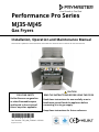
Performance Pro Series
MJ35-MJ45
Gas Fryers
Installation, Operation and Maintenance Manual
This manual is updated as new information and models are released. Visit our website for the latest manual.
Part Number: FRY_IOM_8196042 09/2018
*8196042*
FOR YOUR SAFETY
Do Not Store or use gasoline
or other flammable vapors
and liquids in the vicinity of
this or any other appliance.
OriginalInstructions
CAUTION
READ THE INSTRUCTIONS BEFORE USING THE FRYER.
Read these instructions for use carefully so as to
familiarize yourself with the appliance before
connecting it to its gas supply.
Keep these instructions for future reference.
Your Growth Is Our Goal

i
NOTICE
IF, DURING THE WARRANTY PERIOD, THE CUSTOMER USES A PART FOR THIS FRYMASTER FOODSERVICE
EQUIPMENT OTHER THAN AN UNMODIFIED NEW OR RECYCLED PART PURCHASED DIRECTLY FROM
FRYMASTER DEAN, OR ANY OF ITS AUTHORIZED SERVICERS, AND/OR THE PART BEING USED IS
MODIFIED FROM ITS ORIGINAL CONFIGURATION, THIS WARRANTY WILL BE VOID. FURTHER, FRYMASTER
DEAN AND ITS AFFILIATES WILL NOT BE LIABLE FOR ANY CLAIMS, DAMAGES OR EXPENSES INCURRED
BY THE CUSTOMER WHICH ARISE DIRECTLY OR INDIRECTLY, IN WHOLE OR IN PART, DUE TO THE
INSTALLATION OF ANY MODIFIED PART AND/OR PART RECEIVED FROM AN UNAUTHORIZED SERVICE
CENTER.
NOTICE
This appliance is intended for professional use only and is to be operated by qualified personnel only. A
Frymaster Factory Authorized Servicer (FAS) or other qualified professional should perform installation,
maintenance, and repairs. Installation, maintenance, or repairs by unqualified personnel may void the
manufacturer’s warranty. See Chapter 1 of this manual for definitions of qualified personnel.
NOTICE
This equipment must be installed in accordance with the appropriate national and local codes of the
country and/or region in which the appliance is installed. See NATIONAL CODE REQUIREMENTS in
Chapter 2 of this manual for specifics.
NOTICE TO U.S. CUSTOMERS
This equipment is to be installed in compliance with the basic plumbing code of the Building Officials and
Code Administrators International, Inc. (BOCA) and the Food Service Sanitation Manual of the U.S. Food
and Drug Administration.
DANGER
Instructions to be followed in the event the operator smells gas or otherwise detects a gas leak must be
posted in a prominent location. This information can be obtained from the local gas company or gas
supplier.
WARNING
Improper installation, adjustment, alteration, service or maintenance can cause property damage, injury, or
death. Read the installation, operating, and maintenance instructions thoroughly before installing or
servicing this equipment. Only qualified service personnel may convert this appliance to use a gas other
than that for which it was originally configured.
FOR YOUR SAFETY
Do not store or use gasoline or other flammable liquids or vapors in the vicinity of this or any other
appliance.
DANGER
The front ledge of the fryer is not a step! Do not stand on the fryer. Serious injury can result from slips or
contact with the hot oil.
DANGER
No structural material on the fryer should be altered or removed to accommodate placement of the fryer
under a hood. Questions? Call the Frymaster Dean Service Hotline at 1-800-551-8633.
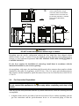
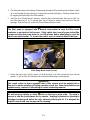
NOTICE
Drawings and photos used in this manual are intended to illustrate operational, cleaning and technical
procedures and may not conform to onsite management operational procedures.

ii
NOTICE TO OWNERS OF UNITS EQUIPPED WITH COMPUTERS
U.S.
This device complies with Part 15 of the FCC rules. Operation is subject to the following two conditions:
1) This device may not cause harmful interference, and 2) This device must accept any interference
received, including interference that may cause undesired operation. While this device is a verified Class
A device, it has been shown to meet the Class B limits.
CANADA
This digital apparatus does not exceed the Class A or B limits for radio noise emissions as set out by the
ICES-003 standard of the Canadian Department of Communications.
Cet appareil numerique n’emet pas de bruits radioelectriques depassany les limites de classe A et B
prescrites dans la norme NMB-003 edictee par le Ministre des Communcations du Canada.
DANGER
Do not spray aerosols in the vicinity of this appliance while it is in operation.
DANGER
The crumb tray in fryers equipped with a filter system must be emptied into a fireproof container at the end
of frying operations each day. Some food particles can spontaneously combust if left soaking in certain
shortening material.
WARNING
Do not bang fry baskets or other utensils on the fryer’s joiner strip. The strip is present to seal the joint
between the fry vessels. Banging fry baskets on the strip to dislodge shortening will distort the strip,
adversely affecting its fit. It is designed for a tight fit and should only be removed for cleaning.
NOTICE
The Commonwealth of Massachusetts requires any and all gas products to be installed by a licensed
plumber or pipe fitter.
WARNING
This appliance is not intended for use by children under the age of 16 or persons with reduced physical,
sensory or mental capabilities, or lack of experience and knowledge, unless they have been given
supervision concerning use of the appliance by a person responsible for their safety. Do not allow children
to play with this appliance.
WARNING
After installation of a gas fryer and after any maintenance to the gas system of a gas fryer-manifold, valve,
burners, etc. – check for gas leaks at all connections. Apply a thick soapy solution to all connections and
ensure there are no bubbles. There should be no smell of gas.
DANGER
When installed, this appliance must be electrically grounded in accordance with local codes, or in the
absence of local codes, with the National Electrical Code, ANSI/NFPA 70, the Canadian Electrical Code,
CSA C22.2 as applicable.
DANGER
When installed, this appliance must conform with local codes, or in the absence of local codes, with the
National Fuel Gas Code, ANSI Z223.1/NFPA54, or the Natural Gas and Propane Installation Code, CSA
B149.1 as applicable or the appropriate national code of the country in which installed.
NOTICE
The appliance must be installed and used in such a way that any water cannot contact the fat or oil.

iii
WARNING
If the electrical power supply cord is damaged, it must be replaced by a Frymaster Factory Authorized
Servicer or a similarly qualified person in order to avoid a hazard.
DANGER
Adequate means must be provided to limit the movement of the appliance without depending upon the gas
line connector and the quick-disconnect device or its associated piping to limit the appliance movement.
All fryers equipped with casters must be stabilized by installing restraining chains. If a flexible gas line is
used, an additional restraining cable must be connected at all times when the fryer is in use.
All fryers equipped with casters must be installed using a connector that complies with the Standard for
Connectors for Moveable Gas Appliances, ANSI Z21.69 or CSA 6.16, and a quick-disconnect device that
complies with the Standard for Quick-Disconnect Devices for Use with Gas Fuel, ANSI Z21.41 or CSA 6.9.
NOTICE
This appliance is intended to be used for commercial applications, for example in kitchens of restaurants,
canteens, hospitals and in commercial enterprises such as bakeries, butcheries, etc., but not for
continuous mass production of food.
DANGER
This appliance must be connected to a power supply having the same voltage and phase as specified on
the rating plate located on the inside of the appliance door.
WARNING
Use caution and wear appropriate safety equipment to avoid contact with hot oil or surfaces that may
cause severe burns or injury.
WARNING
Do not block the area around the base or under the fryers.
WARNING
NEVER drain boil out or cleaning solution into a shortening disposal unit (SDU), a built-in filtration unit, a
portable filter unit. These units are not intended for this purpose and will be damaged by the solution and
void the warranty.
DANGER
Prior to movement, testing, maintenance and any repair on your Frymaster fryer; disconnect ALL electrical
power cords from the electrical power supply.
NOTICE
No warranty is provided for any Frymaster fryer used in a mobile or marine installation or concession.
Warranty protection is only offered for fryers installed in accordance with the procedures described in this
manual. Mobile, marine or concession conditions of this fryer should be avoided to ensure optimum
performance.
WARNING
Operation, installation, and servicing of this product may expose you to chemicals/products including
[Bisphenol A (BPA), glass wool or ceramic fibers, and crystalline silica], which is [are] known to the State
of California to cause cancer, birth defects or other reproductive harm. For more information go to
www.P65Warnings.ca.gov.

i
Performance Pro Series Gas Fryers Models 35 & 45
Installation and Operation Manual
TABLE OF CONTENTS
Page
Chapter 1: Introduction 1-1
Chapter 2: Installation Instructions 2-1
Chapter 3: Operating Instructions 3-1
Chapter 4: Filtration Instructions 4-1
Chapter 5: Preventive Maintenance 5-1
Chapter 6: Operator Troubleshooting 6-1

1-1
PERFORMANCE PRO SERIES GAS FRYERS MODELS 35 & 45
CHAPTER 1: GENERAL INFORMATION
1.1 Applicability and Validity
The Pro Series Gas Fryer has been approved by the European Union for sale and installation
in all EU countries.
This manual is applicable to and valid for all Performance Pro Series Atmospheric Gas Fryers
sold in English-speaking countries, including those in the European Union. Where conflicts
exist between instructions and information in this manual and local or national codes of the
country in which the equipment is installed, installation and operation shall comply with those
codes.
This appliance is only for professional use and shall be used by qualified personnel only, as
defined in Section 1.7.
1.2 Parts Ordering and Service Information
In order to assist you quickly, the Frymaster Factory Authorized Servicer (FAS) or Service Depart-
ment representative requires certain information about your equipment. Most of this information is
printed on a data plate affixed to the inside of the fryer door. Part numbers are found in the Service,
and Parts Manual. Parts orders may be placed directly with your local FAS or distributor. A list of
Frymaster Factory Authorized Servicers (FAS’s) is located on the Frymaster website at
www.frymaster.com. If you do not have access to this list, contact the Frymaster Service Depart-
ment at 1-800-551-8633 or 1-318-865-1711.
When ordering parts, the following information is required:
Model Number:
Serial Number:
Type of Gas or Voltage:
Item Part Number:
Quantity Needed:
Service information may be obtained by contacting your local FAS/Distributor. Service may also be
obtained by calling the Frymaster Service Department at 1-800-551-8633 or 1-318-865-1711. When
requesting service, please have the following information ready:
Model Number:
Serial Number:
Type of Gas:
In addition to the model number, serial number, and type of gas, please be prepared to describe the
nature of the problem and have ready any other information that you think may be helpful in solving
your problem.
RETAIN AND STORE THIS MANUAL IN A SAFE PLACE FOR FUTURE USE.

1-2
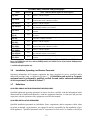
1.3 Safety Information
Before attempting to operate your unit, read the instructions in this manual thoroughly. Throughout
this manual, you will find notations enclosed in double-bordered boxes similar to the ones that
follow.
CAUTION
CAUTION boxes contain information about actions or conditions that may cause or result
in a malfunction of your system.
WARNING
WARNING boxes contain information about actions or conditions that may cause or result
in damage to your system, and which may cause your system to malfunction.
DANGER
DANGER boxes contain information about actions or conditions that may cause or result
in injury to personnel, and which may cause damage to your system and/or cause your
system to malfunction.
Your fryer is equipped with automatic safety features:
1. High temperature detection shuts off gas to the burner assembly should the controlling
thermostat fail.
2. A safety switch built into the drain valve prevents burner ignition with the drain valve even
partially open.
1.4 European Community (CE) Specific Information
The European Community (CE) has established certain specific standards regarding equipment of
this type. Whenever a conflict exists between CE and non-CE standards, the information or
instructions concerned are identified in tables.

1-3
1.5 Equipment Description
All Performance Pro Series fryers are of an open-frypot design with no tubes and have a hand-sized
opening into the deep cold zone, which makes cleaning the frypot quick and easy.
Frypots are constructed of welded, heavy-gauge cold-rolled steel or stainless steel. Heating is
supplied by a burner assembly having multiple gas jets that are focused on ceramic targets located
around the lower side of the frypot. The burner assembly can be configured for natural gas, propane
gas, or manufactured gas. The frypot is drained with a manual ball valve.
Performance Pro Series fryers are equipped with a thermostat probe for precise temperature control.
The probe is located on the centerline of the frypot for rapid response to changes in loads and to
provide the most accurate temperature measurement. Fryers in the 45-model family may have dual-
vat frypots (frypots divided in half). Each half of the dual-vat frypots has its own temperature probe.
Controls on Performance Pro Series fryers vary depending on the model and configuration
purchased. Control options can include thermostat controls, solid-state (analog) controllers, digital
controllers, or Computer Magic 3.5 computers. Not all models are available with all controller
options. Each controller is covered in detail in the separate Frymaster Fryer Controllers User’s
Manual provided with your equipment.
Performance Pro Series fryers may be equipped with an optional melt cycle feature, which pulses the
burner on and off at a controlled rate. The melt cycle feature is designed to prevent scorching and
uneven heating of the frypot when using solid shortening.
Fryers in this series may be configured with pilot ignition or electronic ignition. Fryers configured
with electronic ignition and/or electric controls and all fryers equipped with built-in filtration require
an external source of AC electrical power. Units can be configured for voltages ranging from 100
VAC to 240 VAC.
Fryers equipped with built-in filtration systems are shipped completely assembled. Fryers without
built-in filtration require installation of legs or optional casters at point of use. All fryers are shipped
with a package of standard accessories. Each fryer is adjusted, tested, and inspected at the factory
before crating for shipment.
Model Designations
The primary difference between the fryer models in this series is the size of the frypot.
● 35 models have a frypot capacity of 30-40 pounds of cooking oil or shortening and are
designed for low-volume all-purpose frying.
● 45 models have a frypot capacity of 40-50 pounds of cooking oil or shortening and are
designed for high-volume frying of non-breaded products.
Fryers in the Performance Pro series may be equipped with basket lifts (BL in the designation) and a
built-in filtration system. Fryers having a PMJ designation have no built-in filtration. Garland
Model GF16FR and the Frymaster Model AGF14 are represented by Model PMJ35. Fryers having a
FPP designation have a built-in filtration system under the two leftmost fryers. Those having a
FMP designation have a built-in filtration system under the two leftmost stations and a holding
station. The holding station can be at any position in the battery.

1-4
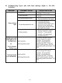
35 Model Family
Model
Built-In
Filtration
Controls
(Note: Millivolt controls require no external power.)
PMJ*35†/GF16FR/
AGF14
No Millivolt. Thermostat knob inside door.
PMJ*35G†
No Millivolt. Thermostat knob on control panel.
PMJ*35GBL†
No Millivolt. Thermostat knob on control panel with push-button basket lift control.
PMJ*35E
No
Electric. Thermostat knob on control panel with ON/OFF switch or Solid State
Controller or Digital Controller.
PMJ*35EC
No Electric. CM III Computer.
PMJ*35EBL
No
Electric. Thermostat knob on control panel with push-button basket lift control
and ON/OFF switch or Basket Lift Timer.
PMJ*35EBLC
No Electric. CM III Computer.
PMJ*35EBLM
No
Electric. Thermostat knob on control panel with push-button basket lift control
plus ON/OFF and melt cycle switches.
PMJ*35EM
No
Electric. Thermostat knob on control panel with ON/OFF and melt cycle
switches.
FMP*35 or
FPP*35
Yes
Millivolt. Thermostat knob on control panel. (Requires external power supply
for filter.)
FMP*35E or
FPP*35E
Yes
Electric. Thermostat knob on control panel with ON/OFF switch or Solid State
Controller or Digital Controller.
FMP*35EC or
FPP*35EC
Yes Electric. CM III Computer.
FMP*35EBL or
FPP*35EBL
Yes
Electric. Thermostat knob on control panel with push-button basket lift control
and ON/OFF switch or Basket Lift Timer.
FMP*35EBLC or
FPP*35EBLC
Yes Electric. CM III Computer.
FMP*35EBLM or
FPP*35EBLM
Yes
Electric. Thermostat knob on control panel with push-button basket lift control
plus ON/OFF and melt cycle switches.
FMP*35EM or
FPP*35EM
Yes
Electric. Thermostat knob on control panel with ON/OFF and melt cycle
switches.
* Insert the number of fryers in the battery (e.g., a PMJ135 has one fryer, a PMJ235 or an FPP235 has two
fryers; an FMP135 has one fryer and one holding station, an FMP235 has two fryers and one holding station.
There is no FPP135).
† Available with pilot ignition only.
45 Model Family
Model
Built-In
Filtration
Controls
(Note: Millivolt controls require no external power.)
PMJ*45†
No Millivolt. Thermostat knob inside door.
PMJ*45G†
No Millivolt. Thermostat knob on control panel.
PMJ*45GBL†
No Millivolt. Thermostat knob on control panel with push-button basket lift control.
PMJ*45E
No
Electric. Thermostat knob on control panel with ON/OFF switch or Solid State
Controller or Digital Controller.
Table continued on following page.

1-5
45 Model Family (continued from previous page)
Model
Built-In
Filtration
Controls
(Note: Millivolt controls require no external power.)
PMJ*45EC
No Electric. CM III Computer.
PMJ*45EBL
No
Electric. Thermostat knob on control panel with push-button basket lift control
and ON/OFF switch or Basket Lift Timer.
PMJ*45EBLC
No Electric. CM III Computer.
PMJ*45EBLM
No
Electric. Thermostat knob on control panel with push-button basket lift control
plus ON/OFF and melt cycle switches.
PMJ*45EM
No
Electric. Thermostat knob on control panel with ON/OFF and melt cycle
switches.
FMP*45 or
FPP*45
Yes
Millivolt. Thermostat knob on control panel. (Requires external power supply
for filter.)
FMP*45E or
FPP*45E
Yes
Electric. Thermostat knob on control panel with ON/OFF switch or Solid State
Controller or Digital Controller.
FMP*45EC or
FPP*45EC
Yes Electric. CM III Computer.
FMP*45EBL or
FPP*45EBL
Yes
Electric. Thermostat knob on control panel with push-button basket lift control
and ON/OFF switch or Basket Lift Timer.
FMP*45EBLC or
FPP*45EBLC
Yes Electric. CM III Computer.
FMP*45EBLM or
FPP*45EBLM
Yes
Electric. Thermostat knob on control panel with push-button basket lift control
plus ON/OFF and melt cycle switches.
FMP*45EM or
FPP*45EM
Yes
Electric. Thermostat knob on control panel with ON/OFF and melt cycle
switches.
* Insert the number of fryers in the battery (e.g., a PMJ145 has one fryer, a PMJ245 or an FPP245 has two
fryers; an FMP145 has one fryer and one holding station, an FMP245 has two fryers and one holding station.
There is no FPP145).
† Available with pilot ignition only.
1.6 Installation, Operating, and Service Personnel
Operating information for Frymaster equipment has been prepared for use by qualified and/or
authorized personnel only, as defined in Section 1.7. All installation and service on Frymaster
equipment must be performed by qualified, certified, licensed, and/or authorized installation
or service personnel, as defined in Section 1.7.
1.7 Definitions
QUALIFIED AND/OR AUTHORIZED OPERATING PERSONNEL
Qualified/authorized operating personnel are those who have carefully read the information in this
manual and have familiarized themselves with the equipment functions, or who have had previous
experience with the operation of the equipment covered in this manual.
QUALIFIED INSTALLATION PERSONNEL
Qualified installation personnel are individuals, firms, corporations, and/or companies which, either
in person or through a representative, are engaged in and are responsible for the installation of gas-
fired appliances. Qualified personnel must be experienced in such work, be familiar with all gas

1-6
precautions involved, and have complied with all requirements of applicable national and local
codes.
QUALIFIED SERVICE PERSONNEL
Qualified service personnel are those who are familiar with Frymaster equipment and who have been
authorized by Frymaster, L.L.C. to perform service on the equipment. All authorized service per-
sonnel are required to be equipped with a complete set of service and parts manuals, and to stock a
minimum amount of parts for Frymaster equipment. A list of Frymaster Factory Authorized Ser-
vicers (FAS’s) is located on the Frymaster website at www.frymaster.com
. Failure to use qualified
service personnel will void the Frymaster warranty on your equipment.
1.8 Shipping Damage Claim Procedure
Your Frymaster equipment was carefully inspected and packed before leaving the factory. The
transportation company assumes full responsibility for safe delivery upon its acceptance of the
equipment for transport.
What to do if your equipment arrives damaged:
1. File a claim for damages immediately, regardless of the extent of damages.
2. Inspect for and record all visible loss or damage, and ensure that this information is noted on
the freight bill or express receipt and is signed by the person making the delivery.
3. Concealed loss or damage that was unnoticed until the equipment was unpacked should be
recorded and reported to the freight company or carrier immediately upon discovery. A
concealed damage claim must be submitted within 15 days of the date of delivery. Ensure that
the shipping container is retained for inspection.
Frymaster
DOES NOT ASSUME RESPONSIBILITY FOR DAMAGE OR LOSS
INCURRED IN TRANSIT.

2-1
PERFORMANCE PRO SERIES GAS FRYERS MODELS 35 & 45
CHAPTER 2: INSTALLATION INSTRUCTIONS
2.1 General Installation Requirements
Qualified, licensed, and/or authorized installation or service personnel, as defined in
Section 1.7 of this manual, should perform all installation and service on Frymaster
equipment.
Conversion of this appliance from one type of gas to another should only be performed by
qualified, licensed, and/or authorized installation or service personnel as defined in
Section 1.7 of this manual.
Failure to use qualified, licensed, and/or authorized installation or service personnel (as
defined in Section 1.7 of this manual) to install, convert to another gas type or otherwise
service this equipment will void the Frymaster warranty and may result in damage to the
equipment or injury to personnel.
Where conflicts exist between instructions and information in this manual and local or
national codes or regulations, installation and operation shall comply with the codes or
regulations in force in the country in which the equipment is installed.
DANGER
Building codes prohibit a fryer with its open tank of hot oil/shortening being installed
beside an open flame of any type, including those of broilers and ranges.
Upon arrival, remove fryer from box and inspect the fryer carefully for visible or concealed damage.
(See Shipping Damage Claim Procedure in Chapter 1.) If there is no damage, remove fryer from
pallet. Discard box and pallet.
DANGER
Frymaster appliances equipped with legs are for stationary installations. Appliances
fitted with legs must be lifted during movement to avoid damage to the appliance
and bodily injury. For movable installations, optional equipment casters must be
used. Questions? Call 1-800-551-8633.
PROPER INSTALLATION IS ESSENTIAL FOR EFFICIENT, TROUBLE-FREE
OPERATION OF YOUR FRYER. ANY UNAUTHORIZED ALTERATIONS MADE
TO THIS EQUIPMENT WILL VOID THE FRYMASTER WARRANTY.

2-2
CLEARANCE AND VENTILATION
DANGER
No structural material on the fryer should be altered or removed to accommodate
placement of the fryer under a hood. Questions? Call the Frymaster/Dean Service
Hotline at 1-800-551-8633.
DANGER
This appliance must be installed with sufficient ventilation to prevent the occurrence
of unacceptable concentrations of substances harmful to the health of personnel in
the room in which it is installed.
The fryer(s) must be installed with a 6" (150 mm) clearance at both sides and back when installed adjacent
to combustible construction; no clearance is required when installed adjacent to noncombustible
construction. If a flue deflector is included with the fryer, ensure that the flue deflector is installed as per
the instruction sheet provided. It is recommended that a flue deflector is used for fryers installed near a
wall cavity that contains combustible materials. A minimum of 24" (600 mm) clearance should be
provided at the front of the fryer.
One of the most important considerations of efficient fryer operation is ventilation. Ensure the fryer is
installed so that products of combustion are removed efficiently, and that the kitchen ventilation system
does not produce drafts that interfere with proper burner operation.
The fryer flue opening must not be placed close to the intake of the exhaust fan, and the fryer must never
have its flue extended in a "chimney" fashion. An extended flue will change the combustion
characteristics of the fryer, causing longer recovery time. It also frequently causes delayed ignition. To
provide the airflow necessary for good combustion and burner operation, the areas surrounding the fryer
front, sides, and rear must be kept clear and unobstructed.
Fryers must be installed in an area with an adequate air supply and adequate ventilation. Adequate
distances must be maintained from the flue outlet of the fryer to the lower edge of the ventilation filter
bank. Filters should be installed at an angle of 45 degrees. Place a drip tray beneath the lowest edge of
the filter. For U.S. installation, NFPA standard No. 96 states, "A minimum distance of 18 inches (450
mm) should be maintained between the flue outlet and the lower edge of the grease filter. " Frymaster
recommends that the minimum distance be 24 inches (600 mm) from the flue outlet to the bottom edge of
the filter when the appliance consumes more than 120,000 BTU per hour.
Information on construction and installation of ventilating hoods can be found in the NFPA standard cited
above. A copy of the standard may be obtained from the National Fire Protection Association, Battery
March Park, Quincy, MA 02269.
NATIONAL CODE REQUIREMENTS
The type of gas for which the fryer is equipped is stamped on the data plate attached to the inside of
the fryer door. Connect a fryer stamped "NAT" only to natural gas, those stamped "PRO" only to
propane gas, and those stamped "MFG" only to manufactured gas.
Installation shall be made with a gas connector that complies with national and local codes, and,
where applicable, CE codes. Quick-disconnect devices, if used, shall likewise comply with national,
local, and, if applicable, CE codes. In the absence of local codes, installation must conform to the

2-3
national Fuel Gas Code, ANSI Z223.1/NFPA 54 or the Natural Gas and Propane Installation code,
CSA B149.1, as applicable including:
1. The appliance and its individual shutoff valve must be disconnected form the gas supply piping
system during any pressure testing of the system at test pressures in excess of ½ psi (3.5 kPa).
2. The appliance must be isolated from the gas supply piping system by closing its individual
manual shutoff valve during any pressure testing of the gas supply piping system at test
pressures equal to or less than ½ psi (3.5 kPa).
ELECTRICAL GROUNDING REQUIREMENTS
All electrically operated appliances must be grounded in accordance with all applicable national and
local codes, and, where applicable, CE codes. In the absence of local codes, the appliance must be
grounded in accordance with National Electrical Code, ANSI/NFPA 70, or the Canadian Electrical
Code, CSA C22.2, as applicable. All units (cord connected or permanently connected) should be
connected to a grounded power supply system. A wiring diagram is located on the inside of the
fryer door. Refer to the rating plate on the inside of the fryer door for proper voltages.
DANGER
If this appliance is equipped with a three-prong (grounding) plug for your protection
against electrical shock, it must be plugged directly into a properly grounded three-
prong receptacle. Do not cut, remove, or otherwise bypass the grounding prong on
this plug!
DANGER
This equipment requires electrical power for operation. Place the gas control valve
in the OFF position in case of a prolonged power outage. Do not attempt to use the
equipment during a power outage.
AUSTRALIAN REQUIREMENTS
To be installed in accordance with AS 5601/ AG 601, local authority, gas, electricity, and any other
relevant statutory regulations.
If casters are fitted, the installation must comply with AS5601 and AS1869 requirements.
SOUTH AFRICA REQUIREMENTS
IMPORTANT INFORMATION FOR THE USER
This appliance may only be installed by a registered SAQCC Gas installer. All registered installers
are issued with a card carrying their registration number. Ask to be shown the card before allowing
the installation work to commence and make a note of the Installer registration number. Upon
completion of the installation, the installer is required to explain the operational details of the
appliance together with the safety instructions. You will be asked to sign acceptance of the
installation and be provided with a completion certificate. You should only sign for acceptance of
the installation when the installation is completed to your satisfaction.
Note that your invoice is required in the event that you wish make a guarantee claim.
IMPORTANT INFORMATION FOR THE INSTALLER.
This appliance may only be installed by a gas installer registered with the South African
qualification and certification committee (SAQCC). The appliance must be installed in accordance

2-4
with the requirements of SANS 10087-1for use with LPG, SANS 827 for use with NG and any fire
department regulations and/or local bylaws applicable to the area. If in doubt, check with the
relevant authority before undertaking the installation. Upon completion of the installation you are
required to fully explain and demonstrate to the user the operational details and safety practices
applicable to the appliance and the installation.
FCC COMPLIANCE
The user is cautioned that any changes or modifications to Frymaster computers not expressly approved by the
party responsible for compliance could void the user’s authority to operate the equipment. Frymaster computers
have been tested and found to comply with the limits for a Class A digital device, pursuant to Part 15 of the FCC
rules. While these devices are verified as Class A devices, they have been shown to meet the Class B limits.
These limits are designed to provide reasonable protection against harmful interference when the equipment is
operated in a commercial environment. This equipment generates, uses, and can radiate radio frequency energy
and, if not installed and used in accordance with the instruction manual, may cause harmful interference to radio
communications. Operation of the equipment in a residential area is likely to cause harmful interference in
which case the user will be required to correct the interference at the user’s expense.
If necessary, the user should consult the dealer or an experienced radio and television technician for
additional suggestions.
The user may find the booklet "How to Identify and Resolve Radio-TV Interference Problems"
helpful. It is prepared by the Federal Communications Commission and is available from the U.S.
Government Printing Office, Washington, DC 20402, Stock No. 004-000-00345-4.
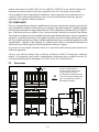
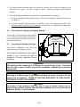
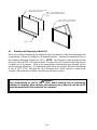
2.2 Dimensions
15.62
(397)
31.24
(794)
46.86
(1190)
31.55
(801)
35.75
(908)
6.10
(155)
36.50
(927)
46.00
(1168)
47.67
(1211)
49.12
(1248)
57.82
(1469)
3.00
(76)
6.00
(152)
CORDSET
8.40
(213)
INCHES
(MM)
12.83
(326)
45
The45inasinglecabinetis
availablewithanoptionallower
reargasconnection,which
accommodatesinstallationscloser
tothewall.Thegasassembly,108‐
5651,isavailablewithanNPT‐to‐
BSPadapter,813‐0540.
GasConnection

2-5
2.3 Caster/Leg Installation
DANGER
DO NOT install this appliance without legs or casters.
Depending upon the specific configuration ordered, the fryer might have been shipped without
installed casters or legs. If casters or legs are installed, you may skip this section and proceed to
Section 2.4, Pre-Connection Preparations. DO NOT INSTALL THIS APPLIANCE WITHOUT
CASTERS OR LEGS.
If your fryer requires the installation of casters/legs, install them in accordance with the
instructions included in your accessory package.
On an appliance with casters; the installation shall be made with a connector that complies with the
Standard for Moveable Gas Appliances, ANSI Z21.69 • CSA 6.16, and a quick disconnect device
that complies with the Standard for Quick-Disconnect Devices for Use With Gas Fuel, ANSI Z21.41
• CSA 6.9.
2.4 Pre-Connection Preparations
DANGER
Do not connect this appliance to the gas supply before completing each step in this
section.
After the fryer has been positioned under the fry station exhaust hood, ensure the following has been
accomplished:
1. Adequate means must be provided to limit the movement of fryers without depending upon the
gas line connections and the quick-disconnect device or its associated piping to limit the
Gas
Connection
INCHES
(MM)
46.86
(1190)
31.24
(793)
36.50
(927)
35.75
(908)
46.00
(1168)
FILTER
31.55
(801)
3.00
(76)
6.10
(155)
23.63
(600)
2.50
(64)
50.64
(1286)
8.40
(213)
FOOD WARMER
(OPTIONAL)
HEAT LAMP
5.50' CORD SET
120V
6.00
(152)
HEAT LAMP
CORD SET
CORD SET
CORD SET
34.55
(878)
15.62
(397)
41.00
(1041)
SINGLE
49.12
(1248)
57.82
(1469)
47.67
(1211)
12.83
(326)
The35inasinglecabinetisavailable
withanoptionallowerreargas
connection,whichaccommodates
installationsclosertothewall.The
gasassembly,108‐5651,isavailable
withanNPT‐to‐BSPadapter,
813‐0540.
35
Gas
Connection

2-6
appliance movement. If a flexible gas hose is used, a restraining cable must be connected at all
times when the fryer is in use. The restraining cable and installation instructions are packed with
the flexible hose in the accessories box that was shipped with your unit.
2. Single unit fryers must be stabilized by installing restraining chains on fryers equipped with
casters or anchor straps on fryers equipped with legs. Follow the instructions shipped with the
casters/legs to properly install the chains or straps.
DANGER
Do not attach an apron drain board to a single fryer. The fryer may become
unstable, tip over, and cause injury. The appliance area must be kept free and clear
of combustible materials at all times.
Level fryers equipped with legs by screwing out the legs approximately 1 inch, and then adjust them
so that the fryer is level and at the proper height in the exhaust hood. Frymaster recommends that the
minimum distance from the flue outlet to the bottom edge of the filter be 24 inches (600 mm) when
the appliance consumes more than 120,000 BTU per hour.
3. For fryers equipped with casters, there are no built-in leveling devices. The floor where the fryer
is to be installed must be level.
4. Test the fryer electrical system: Verify correct voltage and connect per National codes and
regulations.
a. Plug the fryer electrical cord(s) into a grounded electrical receptacle.
b. Place the power switch in the ON position.
For fryers equipped with thermostat controls, verify that the power and heat lights are lit.
For fryers having computer or digital displays, verify that the display indicates CYCL..
c. Place the fryer power switch in the OFF position. Verify that the power and heat lights are
out, or that the display is blank.
5. Refer to the data plate on the inside of the fryer door to verify that the fryer burner is configured
for the proper type of gas before connecting the gas line quick-disconnect device or piping from
the gas supply line.
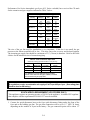
6. Verify the minimum and maximum gas supply pressures for the type of gas to
be used in accordance with the accompanying tables:
7. For fryers equipped with a built-in filter system and/or basket lifts, plug the
electrical cord(s) into a power receptacle behind the fryer.
Non- CE Standard for Gas Pressure
Model 35/GF16FR Model 45
Gas T
y
pe Nat LP Nat LP
Min Pressure W.C/kpa/mba
r
6/1.49/14.93 11/2.74/27.37 6/1.49/14.93 11/2.74/27.37
Max Pressure W.C/kpa/mba
r
14/3.48/34.84 14/3.48/34.84 14/3.48/34.84 14/3.48/34.84
Orifice Size (mm) 1.7 1.05 1.45 0.86
N
umber of Orifices 9 9 18 18
Manifold Pressure (WC) 4.0 10.0 3.0 8.25
NOTE:Gas
specificationsare
includedonappliance
dataplatelocated
insidethedoor.

2-7
2.5 Connection to Gas Line
DANGER
Before connecting new pipe to this appliance, the pipe must be blown out
thoroughly to remove all foreign material. Foreign material in the burner and gas
controls will cause improper and dangerous operation.
DANGER
When pressure-testing incoming gas supply lines, disconnect the fryer from the gas
line if the test pressure will be ½ PSIG (3.45 kPa, 13.84 inches W.C.) or greater to
avoid damage to the fryer’s gas tubes and gas valve(s).
DANGER
The appliance and its individual shutoff valve must be disconnected from the gas supply
piping system during any pressure testing of that system at test pressures in excess of ½
PSIG (3.5 kPa, 14.07 inches W.C.).
DANGER
The appliance must be isolated from the gas supply piping system by closing its individual
manual shutoff valve during any pressure testing of the gas supply system at test pressures
equal to or less than ½ PSIG (3.5 kPa, 14.07 inches W.C.).
CE Standard for Gas Pressure
Model 35/GF16FR Model 45
Gas T
y
pe G20 G25 G30 G31 G20 G25 G30 G31
Rate (kW NET) 27 28.5
Pressure (mbar) 20 20-25 37-50 37-50 20 20-25 37-50 37-50
Orifice Size (mm) 1.70 1.70 1.05 1.05 1.40 1.40 0.86 0.86
N
umber of Orifices 9 9 9 9 18 18 18 18
Manifold Pressure (mbar) 9 13,5 21,5 22,5 7,5 10 20,6 20,6
Australian Standard for Gas Pressure
Model 35/GF16FR/AGF14 Model 45
Gas T
y
pe Nat LP Nat LP
Min Pressure 1.13kpa 2.75 kpa 1.13kpa 2.75 kpa
Max Pressure 5.0 kpa 7.0 kpa 5.0 kpa 7.0 kpa
Orifice Size (mm) 1.7 1.05 1.20 0.81
N
umbe
r
of Orifices 9 9 18 18
Manifold Pressure 0.80 kpa 2. 5 kpa 0.96 kpa 2.2 kpa
Gas Consumption (per hour) 107M
j
107M
j
110M
j
110M
j

2-8
Performance Pro Series Atmospheric gas fryers (J1C Series excluded) have received the CE mark
for the countries and gas categories indicated in Table 3 below.
BE
I2E+(S)
I3P
G20/G25
G31
20/25
37
DE
I2 ELL
13P
G20/G25
G31
20
50
FR
II2Esi3P
G20/G25
G31
20/25
37 ET 50
LU
I2E G20/G25 20/25
ES
II2H3P
G20
G31
20
37 ET 50
NL
II2L3P
G25
G31
25
50
IE-PT-GB
II2H3P
G20
G31
20
37
DK-GR-IT
I2 H G20 20
Table 3: CE Approved Gas Categories
Country Category Gas
Pressure
(mbar)
The size of the gas line used for installation is very important. If the line is too small, the gas
pressure at the burner manifold will be low. This may cause slow recovery and delayed ignition.
The incoming gas supply line should be a minimum of 1½" (38 mm) in diameter. Refer to the Table
4 below for the minimum sizes of connection piping.
Table 4: Gas Connection Pipe Sizes
(Minimum incoming pipe size should be 1-1/2" (38 mm))
Natural 3/4" (19 mm) 1" (25 mm) 1-1/4" (33 mm)
Propane 1/2" (13 mm) 3/4" (19 mm) 1" (25 mm)
Manufactured 1" (25 mm) 1-1/4" (33 mm) 1-1/2" (38 mm)
* For distances of more than 20 feet (6 meters)
and/or more than four fittings or elbows, increase
the connection by one pipe size.
Gas Single Unit 2 - 3 Units 4 Units*
CE Standard
CE regulations require a combustion air supply of 2m
3
/h per kW per fryer. (See rating plate
affixed to door for kW rating.)
1. Connect the quick-disconnect hose to the fryer quick-disconnect fitting under the front of the
fryer and to the building gas line. The gas inlet connection will be up to 1.5” NPT (38.1mm),
depending on the number of fryers in the battery. The gas connection point will be about 13”
SOUTH AFRICA REQUIREMENT (LPG FRYERS ONLY)
This appliance requires an operating pressure of 2,8 kPa at the appliance. A suitable LPG regulator
that complies with the requirements of SANS 1237 must be installed.

2-9
(326mm) from the floor. The left-to-right position will vary according to the number of fryers in
the battery.
NOTE: Some fryers are configured for a rigid connection to the gas supply line. These units are
connected to the gas supply line at the rear of the unit.
When using thread compound, use very small amounts on male threads only. Use a pipe thread
compound that is not affected by the chemical action of LP gases (Loctite PST567 sealant is one
such compound). DO NOT apply compound to the first two threads. Applying compound to the
first two threads will cause clogging of the burner orifices and control valve.
2. Open the gas-supply valve to the fryer and check all piping, fittings, and gas connections for
leaks. A soap and water solution should be used for this purpose.
DANGER
All connections must be sealed with a joint compound suitable for the gas being
used and all connections must be tested with a solution of soapy water before
lighting any pilots.
DANGER
Never use matches, candles, or any other ignition source to check for leaks. If gas
odors are detected:
● Shut off the gas supply to the appliance at the main shut-off valve or bottle.
● Extinguish all naked flames.
● Do not operate any electrical appliances in the area.
● Ventilate the area.
● Check for leaks as detailed in this manual using a solution of soapy solution.
● Immediately contact the local gas company or an authorized service agency for
service.
If odor persists, contact the dealer or gas supplier immediately.
DANGER
In the event of a burn-back, where the flame burns back to the jet, immediately turn
the gas supply off at the control valve on the panel. After ensuring the flame is
extinguished, wait for I minute and re-light the appliance in the normal manner.
Should the appliance again burn back, close the control valve and call a service
technician. Do not use the appliance again until the service technician has declared
that it is safe to do so.
3. Close the fryer drain valve and fill the frypot with water and boil-out solution to the bottom OIL-
LEVEL line at the rear of the frypot. Light the fryer and perform the boil-out procedures that are
described in the "Lighting Instructions" and "Boiling Out the Frypot" topics found in Chapter 3
of this manual.
DANGER
"Dry-firing" your unit will cause damage to the frypot and can cause a fire. Always
ensure that melted shortening, cooking oil, or water is in the frypot before firing your
unit.
Page is loading ...
Page is loading ...
Page is loading ...
Page is loading ...
Page is loading ...
Page is loading ...
Page is loading ...
Page is loading ...
Page is loading ...
Page is loading ...
Page is loading ...
Page is loading ...
Page is loading ...
Page is loading ...
Page is loading ...
Page is loading ...
Page is loading ...
Page is loading ...
Page is loading ...
Page is loading ...
Page is loading ...
Page is loading ...
Page is loading ...
Page is loading ...
Page is loading ...
Page is loading ...
Page is loading ...
Page is loading ...
Page is loading ...
Page is loading ...
Page is loading ...
Page is loading ...
Page is loading ...
Page is loading ...
-
 1
1
-
 2
2
-
 3
3
-
 4
4
-
 5
5
-
 6
6
-
 7
7
-
 8
8
-
 9
9
-
 10
10
-
 11
11
-
 12
12
-
 13
13
-
 14
14
-
 15
15
-
 16
16
-
 17
17
-
 18
18
-
 19
19
-
 20
20
-
 21
21
-
 22
22
-
 23
23
-
 24
24
-
 25
25
-
 26
26
-
 27
27
-
 28
28
-
 29
29
-
 30
30
-
 31
31
-
 32
32
-
 33
33
-
 34
34
-
 35
35
-
 36
36
-
 37
37
-
 38
38
-
 39
39
-
 40
40
-
 41
41
-
 42
42
-
 43
43
-
 44
44
-
 45
45
-
 46
46
-
 47
47
-
 48
48
-
 49
49
-
 50
50
-
 51
51
-
 52
52
-
 53
53
-
 54
54


Frymaster Footprint Pro 35/45 Operational Manual
- Category
- Deep fryers
- Type
- Operational Manual
Ask a question and I''ll find the answer in the document
Finding information in a document is now easier with AI
Related papers
-
Frymaster RE80 Operating instructions
-
 Frymaster YSCF14G User manual
-
 Frymaster YSCF14G User manual
-
 Frymaster 45 Operating instructions
-
 Frymaster HD21814G User manual
-
Frymaster ESG35T Owner's manual
-
 Frymaster 47 Series User manual
-
 Frymaster 2836 Series Electric Fryers w/out Float Switch Operational Manual
-
 Frymaster *8196329* User manual
-
 Frymaster YSCFHC18G Gas Series User manual


Other documents
-
Patriot GF14 User manual
-
 FRYCLONE 259FLTRM50 User manual
-
 VULCAN & WOLF QuickFry Start Up User guide
-
 VULCAN & WOLF QuickFry Start Up User guide
-
 IKON IGF-75/80 Owner's manual
-
ALFI BRAND AB2534-PC User manual
-
Magikitchn 40S User manual
-
-
Pitco Frialator 65C+, 150K BTU User manual
-
Dean SM40 Installation & Operation Manual


