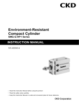
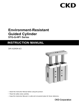
CKD SMG-HP1 Series is a compact cylinder with a built-in switch that can be used for a variety of applications. It is available in a variety of bore sizes and stroke lengths, and can be mounted in any orientation. The built-in switch can be used to sense the position of the piston, and can be used to control the operation of the cylinder or other devices. The CKD SMG-HP1 Series is a versatile and reliable cylinder that is ideal for a wide range of applications.
Some of the potential use cases for the CKD SMG-HP1 Series compact cylinder include:
- Controlling the position of a robotic arm
- Actuating a valve
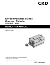


-
 1
1
-
 2
2
-
 3
3
-
 4
4
-
 5
5
-
 6
6
-
 7
7
-
 8
8
-
 9
9
-
 10
10
-
 11
11
-
 12
12
-
 13
13
-
 14
14
-
 15
15
-
 16
16
-
 17
17
-
 18
18
-
 19
19
-
 20
20
-
 21
21
-
 22
22
-
 23
23
-
 24
24
-
 25
25
-
 26
26
-
 27
27
-
 28
28
-
 29
29
-
 30
30
-
 31
31
-
 32
32
-
 33
33


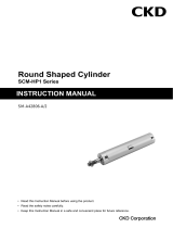
CKD SMG-HP1 Series is a compact cylinder with a built-in switch that can be used for a variety of applications. It is available in a variety of bore sizes and stroke lengths, and can be mounted in any orientation. The built-in switch can be used to sense the position of the piston, and can be used to control the operation of the cylinder or other devices. The CKD SMG-HP1 Series is a versatile and reliable cylinder that is ideal for a wide range of applications.
Some of the potential use cases for the CKD SMG-HP1 Series compact cylinder include:
- Controlling the position of a robotic arm
- Actuating a valve
Ask a question and I''ll find the answer in the document
Finding information in a document is now easier with AI
Related papers
-
 CKD SMG-G-HP1 Series User manual
-
 CKD SSD2-G-HP1 Series User manual
-
 CKD SCM-HP1 Series User manual
-
 CKD STM-HP1 Series User manual
-
 CKD STG-G-HP1 Series User manual
-
 CKD STS・STL-G-HP1 Series User manual
-
 CKD SSD2-HP1 Series User manual
-
 CKD LCG-HP1 Series User manual
-
 CKD HMC-HP1 Series User manual
-
 CKD LCR-HP1 Series User manual


Other documents
-
 Tsubaki ED Series User manual
-
SMC ZXP7–X1-ASSISTA Vacuum Gripper User manual
-
SMC ML2B Series Hyrodless Monosashi Kun Stroke Reading Cylinder User manual
-
Ranger Products Tire Shop Combo Owner's manual
-
Kogan FSAEXT360AA User guide
-
 SUNNY Health Fitness SF-E320002 User manual
-
 SUNNY Health Fitness E321003 User manual
-
Argos davina mccall 2 in 1 Cross Trainer Exercise Bike User manual
-
BLADEZ E300 Owner's manual
-
ProForm 425 CSE User manual


