S.R.Smith Automated Wall-Mount Thermal Pool Cover Reel Owner's manual
- Category
- Wall & ceiling mounts accessories
- Type
- Owner's manual

Installation and Operation Manual
Manuel d’installation et d’utilisation
Manual de instalación y operación
Automated Wall Mounted Thermal Pool Cover
Storage Reel
WARNING
FOR YOUR SAFETY – This product must be installed and serviced by a contractor who is licensed and qualified in pool equipment by the jurisdiction in which the product will be installed
where such state or local requirements exist. The maintainer must be a professional with sufficient experience in pool equipment installation and maintenance so that all of the instructions
in this manual can be followed exactly. Before installing this product, read and follow all warning notices and instructions that accompany this product. Failure to follow warning notices
and instructions may result in property damage, personal injury, or death. Improper installation and/or operation may void the warranty.
Improper installation and/or operation can create unwanted electrical hazard which may cause serious injury, property damage, or death.
ATTENTION INSTALLER – This manual contains important information about the installation, operation and safe use of this product. This information should be given
to the owner/operator of this equipment.

Page 2
ENGLISH S.R.Smith® Automated Wall Mounted Thermal Pool Cover Storage Reel | Installation & Operation Manual
Table of Contents
Section 1. Important Safety Instructions .........3
Section 2. Installation ........................................4
2.1 Installing the Wall Brackets ............................4
2.2 Mounting the Roller ........................................5
2.3 Attaching the Pool Cover ...............................5
2.4 Mounting Multiple Rollers ..............................6
Section 3. Operation .......................................... 9
3.1 Remote Overview ...........................................9
3.2 Changing Motor Direction ..............................9
3.3 Placing the Cover Onto the Pool ..................10
3.4 Pulling the Cover Off the Pool ...................... 10
3.5 Loss of Power ..............................................10
Section 4. Maintenance ...................................10
Section 5. Specifications .................................11

Page 3
S.R.Smith® Automated Wall Mounted Thermal Pool Cover Storage Reel | Installation & Operation Manual ENGLISH
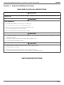
Section 1. Important Safety Instructions
READ AND FOLLOW ALL INSTRUCTIONS
WARNING
Thermal covers are not safety covers and will not support the weight of humans or animals. Do not attempt to walk on or swim
under the cover.
WARNING
AVOID DROWNING RISK
• Keep children away. Children or objects can not be seen under cover.
• This is not a safety cover. Keep off cover. It will not support weight.
• Remove cover(s) completely before entry of bathers. Entrapment possible.
• Unsecured or improperly secured covers are a hazard.
• Failure to follow any instructions may result in injury or drowning.
WARNING
• It is important for the safety of everyone to follow these instructions. The roller system is not intended for use by very young children or infirm
people without supervision.
• Young children should be supervised to ensure that they do not play with the rollers.
• Do not allow children to play with fixed controls.
CAUTION
• Frequently examine the installation for imbalance and signs of wear of damage to cables.
• Do not use if repairs are necessary.
• Never attach the cords to the blanket and then tie the other end off to a fixed object.
• Broken blanket/roller attachment cords should be replaced immediately to prevent blanket creasing.
SAVE THESE INSTRUCTIONS

Page 4
ENGLISH S.R.Smith® Automated Wall Mounted Thermal Pool Cover Storage Reel | Installation & Operation Manual
Section 2. Installation
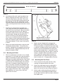
2.1 Installing the Wall Brackets
1. Measure the width of pool and mark the center
line, transfer this line to base of wall.
2. Check which side of the center line the power is
located on. The motor side of roller should be on
the same side as the power.
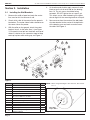
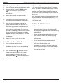
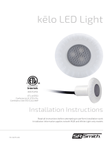
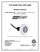
3. With the roller on the ground, attach the motor
bracket, Item 4, to the roller, Item 1 (see Figure
1). Be careful to not pull out the black end cap of
motor. It is better to use some duct tape to keep
end cap in place while setting up, see Figure 2.
4. At the other end of roller, apply some anti-seize
lubricant on the shaft and slide on the bearing,
Item 13. The set screws should be facing
outwards, DO NOT tighten the set screws yet.
This allows you to slide the bearing if the holes
do not align with the mounting bracket at Step 9.
5. Now measure from the center of the bolt holes
of motor bracket to the center of the bolt holes
of the bearing case and mark a center line on
the roller. See Figure 3.
1
2
3
8
12
9
10
11
6
57
5
6
7
4
13
2
2
38
Figure 1.
Item No. Description QTY
1 Wall Roller Assembly 1
2 AR Wall Mounted End Frame 2
3 AR Bearing Mount Plate M12 2
4 AR End Frame Motor Bracket 1
5 M12 Split Lock Washer, DIN 127B, 316SS 4
6M12 Flat Washer, DIN 125, 316SS, 13 mm
ID x 24 mm OD x 2.5 mm THK 4
7 Bolt, M12 x 40 mm, Hex Head 4
8 Tube Closure Plug 65 mm x 65 mm 6
9 Gland Insert (Strain Relief) PG11 1
10 M8 Flat Washer, 316SS 4
11 M8 x 1.25, Nyloc Nut, 316SS 4
12 144" Strap, Pool Cover; Inc. Dowel 5
13 SP206 Bearing Housing with 30 mm
Stainless Bearing 1
NOTE: When storage reel length is less than 18 ft, QTY of Item
12 is 3.
Duct Tape
Cap in Place
Figure 2.

Page 5
S.R.Smith® Automated Wall Mounted Thermal Pool Cover Storage Reel | Installation & Operation Manual ENGLISH
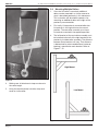
Measure This Distance
Figure 3.
6. At the base of the wall, mark the width of the
roller by aligning the center mark on the wall
with the center mark on the roller. Then mark
the center of the bolt holes (motor bracket and
bearing ends) on the wall. Depending on how
high up the roller will be mounted use a level to
mark a vertical (plumb) line on the wall or a laser
level.
7. Position the wall bracket to the height you
want, align the center of the bracket to one of
the vertical lines from Step 6. Mark the location
of one mounting hole on the wall. Remove
the bracket and install the mounting hardware
at that location. Realign the bracket to the
vertical line and uses the mounting hardware
that was just installed to hold the bracket in
place. Markthe three remaining mounting holes,
remove the bracket, and install the remaining
mounting hardware. Finally, mount the bracket
in place.
8. Mount the second wall bracket using the same
method described in Step 7. Ensure that this
bracket is aligned with the opposite vertical line
from Step 6 and is aligned horizontally with the
bracket installed in Step 7.
2.2 Mounting the Roller
1. With the wall brackets mounted, use a suitable
equipment lift, to lift roller up on top of brackets.
Apply a small bead of silicon around stainless
bearing casting before bolting down, See Figure
4. Slide the mounting plates, Item 3 in Figure 1,
into the tubes that are protruding from the wall.
The holes in the plates need to align with the
holes in the tube. The bolts that hold down the
bearing and motor bracket thread into the hole
in the mounting plate. Once the roller is bolted
down, apply Loctite-242 “Blue,” or equivalent,
to the bearing’s set screw, then install and
tighten the set screws.
Apply Bead of Silicone Around
Perimeter of Bearing Casting
Figure 4.
2. Motors are not shipped with a plug on the
power cord. Have a three-prong (NEMA 5-15
TYP) plug wired by an electrical contractor. Plug
in and turn on power and the check remote. The
brackets have accommodation for routing the
power cable through them, if so desired. Install
the tube closure plugs, Item 8, Figure 1 after the
wiring is complete. Note the remote will come
with a short limit setting. Adjust the limits as
described later in this document per the flow
chart in section 3.2, Changing Motor Direction.
2.3 Attaching the Pool Cover
1. Put the covers onto the pool with the safety
warnings facing upward onto the water.
2. Attach the strap to pool cover by placing the
dowel attached to cover through the loop of
rope at the end of the strap, reference Figure 5.
3. Attach cords to roller by placing the dowel at
theend of the strap through the loop of rope
onthe roller. Similar to how the strap is attached
to the pool cover.

Page 6
ENGLISH S.R.Smith® Automated Wall Mounted Thermal Pool Cover Storage Reel | Installation & Operation Manual
Figure 5.
4. Making sure all attachment straps are close to
the same length.
5. Using the remote control, wind the strap and
cover on to the roller.
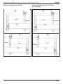
2.4 Mounting Multiple Rollers
1. Once the first roller is mounted, additional
rollers can be mounted in a similar manner to
what is described previously in this document.
This instruction will describe the process for
mounting an additional roller to the right of the
previously mounted roller.
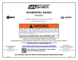
2. First verify if the previously mounted roller has
its brackets in the high mount or low mount
position. The next roller assembly must have
itsbrackets mounted in the opposite position.
3. The left bracket of the next roller assembly must
be installed to the left of the right bracket of the
previously installed roller assembly. The distance
between these brackets will vary. That distance
is determined by what combination of motor or
bearing is mounted on each bracket. Refer to
Figures 7-10.
High Mount
Low Mount
Figure 6.

Page 7
S.R.Smith® Automated Wall Mounted Thermal Pool Cover Storage Reel | Installation & Operation Manual ENGLISH
Bearing at Both Brackets – 28 3/8"
28 3/8"
24 23/32"
28 3/8"
24 23/32"
Figure 7.
Motor at RT Roller, Bearing at LT Roller –
27 7/8" Spacing
27 7/8"
24 23/32"
27 7/8"
24 23/32"
Figure 8.

Page 8
ENGLISH S.R.Smith® Automated Wall Mounted Thermal Pool Cover Storage Reel | Installation & Operation Manual
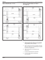
Motor at Both Brackets – 27 1/2"
27 1/2"
24 23/32"
27 1/2"
24 23/32"
Figure 9.
Bearing at RT Roller, Motor at LT Roller –
27 7/8" Spacing
27 7/8"
24 23/32"
27 7/8"
24 23/32"
Figure 10.
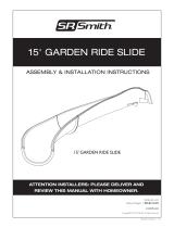
4. Measure and mark the distance on the wall per
the illustrations above. Then mark a plumb line
using a level or use a laser level.
5. Mark a horizontal line from the bottom mounting
plate of the previously installed bracket to where
it intersects the plumb line.
6. Align new bracket to the horizontal and
verticallines.
7. Install this bracket per the instructions.
8. Install the right bracket and roller per
theinstructions.

Page 9
S.R.Smith® Automated Wall Mounted Thermal Pool Cover Storage Reel | Installation & Operation Manual ENGLISH
Section 3. Operation
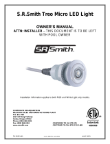
3.1 Remote Overview
Take Cover Off Pool
Stop
Put Cover Onto Pool
LED Light Indicator
Take Cover Off Pool
Stop
Put Cover Onto Pool
LED Light Indicator
Channel Selection Button
Single Channel
Remote
Multi-Channel
Remote
mymy
Figure 11.
3.2 Changing Motor Direction
NOTE:
If the motor rotates in the opposite direction than desired, i.e., rolls down whenthe UP button is pressed.
Press and hold the STOP button for more than5seconds until the motor “jiggles” back and forth.
To Adjust the UP Limit: To Adjust the DOWN Limit:
Press the UP Button. The roller should
continue to move by itself until it stops
on the existing UP limit.
Press the DOWN Button. The roller
should continue to move by itself until
it stops on the existing DOWN limit.
Press and hold the UP and DOWN
button at the same time until the roller
“jiggles” back and forth.
Press and hold the UP and DOWN
button at the same time until the roller
“jiggles” back and forth.
Move the roller to the new desired
end limit using the UP or DOWN
buttons as necessary.
or
Move the roller to the new desired end
limit using the UP or DOWN buttons
as necessary.
or
Press and hold the STOP button until
the roller “jiggles” back and forth to
memorize the new end limit.
Press and hold the STOP button until
the roller “jiggles” back and forth to
memorize the new end limit.
NOTE: Motors are not rated for continuous operation and may stop for “thermal cut-out” after 4-7 minutes ofoperation.
This is normal. If this occurs during commissioning, then motor cannot resume operation for10-15minutes.
It should not occur during the normal mode of cover use.

Page 10
ENGLISH S.R.Smith® Automated Wall Mounted Thermal Pool Cover Storage Reel | Installation & Operation Manual
3.3 Placing the Cover Onto the Pool
1. Have the relevant remotes and pull cords ready.
2. Lower the blanket using the DOWN button
( ) on the remote and stop it at a level
whereyou can easily attach the pull cord
totheblanket.
3. Walk the pull cord to the opposite end of
thepool.
4. Position yourself so that you are looking at
theroller and have the pull cord in your hand.
5. Press the down button again and lead the
blanket onto the water as the roller sheds it.
Do not apply excess tension on the rope the
motor must be allowed to shed the blanket at
its own pace. Theoperator is only required to
pull the blanket onto the pool at the same rate
the motor is shedding the blanket from the roller.
Ensure that the pool cover corners are folded
and does not catch on any obstacles. The roller
will automatically stop when the blanket is
fullydeployed.
6. Repeat this process with the next roller.
3.4 Pulling the Cover Off the Pool
1. Have the relevant remotes ready.
2. Position yourself at the opposite end of the pool
and look at the roller with the corresponding
remote in your hand.
3. Press the UP button ( ) and watch as the
blanket automatically retracts off the pool
ontothe roller. Operator must maintain visual
contact through this process and use the
STOPbutton (my) () on the remote should
any problem occur.
4. Repeat this process with the next roller.
3.5 Loss of Power
In the event that the roller loses power for whatever
reason, the blanket should be folded neatly onto the
pool deck using an accordion technique to remove it
from the pool. Do not attempt to roll the blanket up
on the water. Two or more people may be needed to
do this task.
Place the blanket back onto the pool before winding
back onto the roller as the roller may overload if it is
pulling the first layer of the blanket from the bottom
of the folded stack.
Section 4. Maintenance
Pool Cover Care
1. Do not allow covers to crease when loading
them onto rollers. Creases are extremely hard
toremove once engrained makes cover handling
more difficult.
2. Always replace broken roller attachment cords.
The absence of cords can promote creasing.
Replacement cords are available from the
manufacturer.
3. Do not administer concentrated chemicals
(e.g.chlorine) next to or on covers. Doing so
may cause damage to the cover.
4. Lane ropes can remain in the pool while covers
are in use but will lead to some level of wear on
the covers. However broken lane rope segments
can damage the cover.

Page 11
S.R.Smith® Automated Wall Mounted Thermal Pool Cover Storage Reel | Installation & Operation Manual ENGLISH
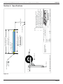
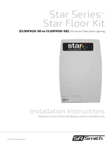
Section 5. Specifi cations
BLANKET WIDTH, 16'6" MAX
BLANKET LENGTH, 82'0" MAX
TUBE CUT LENGTH
BLANKET WIDTH + 24"
NOMINAL BRACKET
C
L
TUBE CUT LENGTH + 4"
84"
MINIMUM HEIGHT
POOL DECK
MOTOR MOUNTING
LEFT END
RIGHT END
8" DIA X .125" WALL
ALUMINUM TUBE
F(X)=354 LB
F(Y)=992 LB
R1 = 935 LB
R2 = 992 LB
NOTES:
EACH ROLLER HAS AN INTERNAL TUBULAR
1.
MOTOR POSITIONED AT ONE END.
EACH MOTOR REQUIES A DEDICATED 120Vac
2.
15A GFCI PROTECTED OUTLET. BY OTHERS
EACH MOTOR HAS A 3.0M ELECTRICAL CORD.
3.
EQUOPOTENTIAL BONDING PER NEC AND
4.
LOCAL CODES. BY OTHERS
HIGH MOUNT
APPROXIMATE ASSEMBLED WEIGHT
USED FOR
CALCULATION
WEIGHT
BLANKET
.132 LBS/FT^2
.26
ROLLER TUBE
3.62 LBS/FT
7.24
OTHER
COMPONENTS
75.6 LBS
152
SCALE: 1:48
SIZE:
DESCRIPTION:
PART NO.:
PLEASE RETURN SIGNED
DRAWING TO SR SMITH IF
APPROVED
SHEET 1 OF 3
P.O. BOX 400 - 1017 S.W. BERG PARKWAY
CANBY, OREGON 97013
PHONE (503) 266-2231
A
DATE:
REV.
DATE:
DRAWN BY:
CHECKED BY:
MOTORIZED WALL ROLLER
COPYRIGHT 2022 S.R. SMITH, LLC.
MATERIAL:
Figure 12.

Page 12
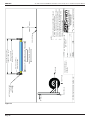
ENGLISH S.R.Smith® Automated Wall Mounted Thermal Pool Cover Storage Reel | Installation & Operation Manual
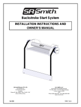
BLANKET WIDTH, 16'6" MAX
BLANKET LENGTH, 82'0" MAX
TUBE CUT LENGTH
BLANKET WIDTH + 24"
NOMINAL BRACKET
C
L
TUBE CUT LENGTH + 4"
84"
MINIMUM HEIGHT
POOL DECK
MOTOR MOUNTING
LEFT END
RIGHT END
8" DIA X .125" WALL
ALUMINUM TUBE
F(X)=354 LB
F(Y)=992 LB
R1=652 LB
R2=992 LB
NOTES:
EACH ROLLER HAS AN INTERNAL TUBULAR
1.
MOTOR POSITIONED AT ONE END.
EACH MOTOR REQUIES A DEDICATED 120Vac
2.
15A GFCI PROTECTED OUTLET. BY OTHERS
EACH MOTOR HAS A 3.0M ELECTRICAL CORD.
3.
EQUOPOTENTIAL BONDING PER NEC AND
4.
LOCAL CODES. BY OTHERS
LOW MOUNT
SCALE: 1:48
SIZE:
DESCRIPTION:
PART NO.:
PLEASE RETURN SIGNED
DRAWING TO SR SMITH IF
APPROVED
SHEET 2 OF 3
P.O. BOX 400 - 1017 S.W. BERG PARKWAY
CANBY, OREGON 97013
PHONE (503) 266-2231
A
DATE:
REV.
DATE:
DRAWN BY:
CHECKED BY:
MOTORIZED WALL ROLLER
COPYRIGHT 2022 S.R. SMITH, LLC.
MATERIAL:
Figure 13.

Page 13
S.R.Smith® Automated Wall Mounted Thermal Pool Cover Storage Reel | Installation & Operation Manual ENGLISH
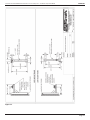
Figure 14.

Page 14
ENGLISH S.R.Smith® Automated Wall Mounted Thermal Pool Cover Storage Reel | Installation & Operation Manual
NOTES

Page 15
S.R.Smith® Automated Wall Mounted Thermal Pool Cover Storage Reel | Installation & Operation Manual ENGLISH
NOTES

S.R. Smith, LLC
1017 SW Berg Parkway
Canby, OR 97013, USA
srsmith.com | 1.800.822.7933
A Fluidra Brand
©2023 S.R. Smith, LLC. All rights reserved. All trademarks are the property of their respective owners.
AWR-20
-
 1
1
-
 2
2
-
 3
3
-
 4
4
-
 5
5
-
 6
6
-
 7
7
-
 8
8
-
 9
9
-
 10
10
-
 11
11
-
 12
12
-
 13
13
-
 14
14
-
 15
15
-
 16
16


S.R.Smith Automated Wall-Mount Thermal Pool Cover Reel Owner's manual
- Category
- Wall & ceiling mounts accessories
- Type
- Owner's manual
Ask a question and I''ll find the answer in the document
Finding information in a document is now easier with AI
Related papers
-
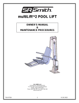 S.R.Smith multiLift™2 Pool Lift Owner's manual
-
 S.R.Smith micro LED Pool Light Installation guide
-
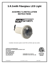 S.R.Smith LED Pool Light for Fiberglass Pools Installation guide
-
 S.R.Smith TREO LED Pool Light Installation guide
-
 S.R.Smith TREO LED Pool Light Owner's manual
-
 S.R.Smith kelo LED Pool Light Installation guide
-
 S.R.Smith micro LED Pool Light Owner's manual
-
 S.R.Smith LED Lit Fiber Optic Star Floor Kit Owner's manual
-
 S.R.Smith Backstroke Start System Installation guide
-
 S.R.Smith poolLUX™ Plus2 Dual Transformer Installation guide


Other documents
-
 SR Smith PAL2 Hi / Lo Portable Aquatic ADA Compliant Pool Lift User guide
-
 S R Smith FLED-C-TR-50 Owner's manual
-
S R Smith GRS10-CR-55-C User manual
-
 SR Smith Residential Board Installation guide
-
S R Smith River Run User manual
-
 SR Smith GRS10-CL-61-C User manual
-
SR Smith FLED-C-TR-30 User manual
-
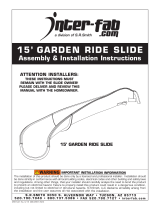 Inter-fab 15’ GARDEN RIDE SLIDE Assembly/Installation Instructions


