Page is loading ...

User Manual
V2.2023 Copyright Safewaze
4 PERSON DOUBLE BRAID ROPE
TEMPORARY
HORIZONTAL LIFELINE
220-00006
Compliant with
OSHA 1926.502, 1910.140, 1910.66

User Manual
V2.2023 Copyright Safewaze Page 1
This product is part of a complete fall protection system. User’s must utilize, and
connect to a Safewaze Horizontal Lifeline (HLL) system with ANSI Z359 compliant
restraint or Personal Fall Arrest Systems (PFAS). This product is not designed, nor
should be used as a component for a Positioning, Suspension, Restraint or Rescue
System. A PFAS is typically composed of a Full Body Harness (FBH), Anchorage, and
a Connecting Device. Connecting Devices used with Safewaze HLLs are Energy
Absorbing Lanyards (EALs) or Self Retracting Lifelines (SRLs). The connection point
to the FBH for use of a Safewaze HLL is the Dorsal D-ring.
WARNING
These instructions must be provided to any person utilizing this equipment. The
worker must read and understand the manufacturer’s instructions for this, and all
other components of the complete Fall Protection System. These instructions must
be followed for the proper use, maintenance, and inspection of this equipment. These
instructions must be kept and made available to workers at all times. Any alteration,
misuse, or use of this equipment outside the scope of the manufacturer’s instructions,
may result in serious injury or death.
A comprehensive Fall Protection Plan must be kept on le and available to all
employees at all times. The employer and users of this equipment must be properly
trained in the installation, use, inspection, and maintenance of this equipment.
The maximum weight capacity of this equipment is 310 lbs. per user, up to
a maximum of four users (including tools and equipment) as specied by ANSI.
The weight capacity of this equipment for two users is 420 lbs. per user
(including tools and equipment).
Consult your doctor if there is reason to doubt your tness to safely absorb the shock
from a fall arrest. Age and tness seriously aect a worker’s ability to withstand falls.
Pregnant women or minors must not use this equipment. Failure to heed this warning
may result in serious injury or death.
Users of this equipment must read and understand this manual in its entirety prior to
use.
Contact Safewaze if you have questions, regarding compatibility of this equipment,
that are not covered in this manual. Do not alter or misuse this equipment. Some
subsystem components could aect the performance and the operation of this
equipment. Do not anchor this product to moving machinery, or hazards that have
chemical, electrical or gaseous characteristics. Failure to comply with this warning
could result in serious injury or death.

User Manual
V2.2023 Copyright Safewaze Page 2
Table of Contents
1 INTRODUCTION & SCOPE OF USE............... 3
2 APPLICABLE SAFETY STANDARDS .............. 3
3 WORKER CLASSIFICATIONS ......................... 3
4 PRODUCT SPECIFIC APPLICATIONS ............ 3
5 LIMITATIONS .................................................... 4
6 COMPATIBILITY OF CONNECTIONS ............. 5
7 MAKING CONNECTIONS ...............................6-7
8 COMPONENTS AND SPECIFICATIONS ......... 8
9 INSTALLATION AND USE ..............................8-12
10 FALL CLEARANCE CHARTS ........................ 13-15
11 INSPECTION AND MAINTENANCE ............... 16
12 LABELS ........................................................... 17
13 INSPECTION LOG .......................................... 17

User Manual
V2.2023 Copyright Safewaze Page 3
2.0 Applicable Safety Standards
Personal Fall Arrest: Safewaze 4 Person Temporary Horizontal Lifelines can be used
as part of a complete Personal Fall Arrest System (PFAS) for up to a maximum of 4
users. The structure utilized for attachment must be capable of withstanding a load of
5,000 lbs. in all directions permitted by the system. The maximum allowable free fall is
6 ft.
4.0 Product Specific Applications
3.0 Worker Classifications
Understand the denitions of those who work in proximity of or may be
exposed to fall hazards.
Qualied Person: A person with an accredited degree or certication, and with
extensive experience or sucient professional standing, who is considered procient
in planning and reviewing the conformity of fall protection and rescue systems.
Competent Person: A highly trained and experienced person who is assigned by the
employer to be responsible for all elements of a fall safety program, including, but not
limited to, its regulation, management, and application. A person who is procient in
identifying existing and predictable hazards, and who has the authority to stop work in
order to eliminate hazards.
Authorized Person: A person who is assigned by their employer to work around or be
subject to potential or existing fall hazards.
It is the responsibility of a Qualied or Competent person to supervise the job
site and ensure safety regulations are complied with.
1.0 Introduction & Scope of Use
Thank you for purchasing a Safewaze 4 Person Temporary Horizontal Lifeline. This
manual must be read and understood in its entirety and used as part of an employee
training program as required by OSHA or any applicable state agency.
This manual and any other instructional material must be available to the user of the
equipment. The user must understand how to safely and eectively use a Horizontal
Lifeline, and all fall protection equipment used in conjunction with such.
The Safewaze 4 Person Temporary Horizontal Lifeline has been designed for your
safety. These Horizontal Lifeline systems are designed to oer users a exible
anchorage between two structures. The lines can also be used to provide a temporary
barrier system.
OSHA REGULATIONS
OSHA 1926.502 Fall Protection Systems Criteria and Practices
OSHA 1910.140 Personal Fall Protection Systems
OSHA 1910.66 Personal Fall Arrest Systems

User Manual
V2.2023 Copyright Safewaze Page 4
Swing Falls: Prior to installation or use, make considerations for eliminating or
minimizing all swing fall hazards. Swing falls occur when the anchor is not directly
above the location where a fall occurs. Always work as close to in line with the anchor
point as possible. Swing falls signicantly increase the likelihood of serious injury or
death in the event of a fall. (See Figure 2)
Fall Clearance Diagram
FIGURE 1 - FALL CLEARANCE CALCULATION DIAGRAM
Fall Clearance: There must be sucient clearance below the anchorage connector to
arrest a fall before the user strikes the ground or an obstruction. When calculating fall
clearance, account for a MINIMUM 2’ safety factor, deceleration distance, user height,
length of Lanyard/SRL, and all other applicable factors. (See Figure 1)
5.0 Limitations
ADynamic Lifeline Sag
BDeployed Energy Absorbing Lanyard
CHarness Stretch
DHeight Of Worker
ESafety Factor
FTotal Required Fall Clearance
***Diagram shown is an EXAMPLE how
to calculate clear fall requirements.
For all applications: Worker Weight Max Capacity for 2 Users
(including all clothing, tools, and equipment) is 420 lbs. for each user.
Capacity range for 4 Users is (130-310 lbs.) for each User
(including all clothing, tools , and equipment)
A
FALL-ARREST
A
FALL-ARREST
F
A
B
C
D
E
ANSI Z359.1
Use this nut with help
of 24mm spanner to provide
appropriate tension to
the rope with minimum
possible sag
CAREFULLY READ
THE INSTRUCTION
MANUAL BEFORE
USING THIS PRODUCT
Ref.: PN 3001A
Batch No:12 18
Use this nut with help
of 24mm spanner to provide
appropriate tension to
the rope with minimum
possible sag
ANSI Z359.1
CAREFULLY READ
THE INSTRUCTION
MANUAL BEFORE
USING THIS PRODUCT
Ref.: PN 3001A
Batch No:12 18

User Manual
V2.2023 Copyright Safewaze
Connectors are compatible with connecting elements when they have been designed
to work together in such a way that their sizes and shapes do not cause their
gate mechanisms to inadvertently open regardless of how they become oriented.
Connectors (hooks, carabiners, and D-rings) must be capable of supporting at least
5,000 lbs. (22.2 kN). Connectors must be compatible with the anchorage or other
system components (See Figure 4). Do not use equipment that is not compatible.
Non-compatible connectors may unintentionally disengage (See Figure 3). Connectors
must be compatible in size, shape, and strength. Self-locking snap hooks and
carabiners are required by ANSI Z359 and OSHA guidelines. Contact Safewaze
if you have any questions about compatibility.
FIGURE 3 - UNINTENTIONAL DISENGAGEMENT
NOTE: SOME SPECIALTY CONNECTORS HAVE ADDITIONAL REQUIREMENTS.
CONTACT SAFEWAZE WITH QUESTIONS.
FIGURE 2
Using a connector that is undersized or irregular in shape (1) to connect a snap hook
or carabiner could allow the connector to force open the gate of the snap hook or
carabiner. When force is applied, the gate of the hook or carabiner presses against
the non-compliant part (2) and forces open the gate (3). This allows the snap hook or
carabiner to disengage (4) from the connection point.
Page 5
6.0 Compatibility Of Connections
A
FALL-ARREST
Use this nut with help
of 24mm spanner to provide
appropriate tension to
the rope with minimum
possible sag
ANSI Z359.1
CAREFULLY READ
THE INSTRUCTION
MANUAL BEFORE
USING THIS PRODUCT
Ref.: PN 3001A
Batch No:12 18
3 - Gate opens
2 - Gate presses
against
non-complaint
part
4 - Parts disengage.1 - Non-compliant part

User Manual
V2.2023 Copyright Safewaze Page 6
7.0 Making Connections
Snap Hooks and Carabiners must be ANSI Z359.12 compliant with a double locking
gate. Ensure all connections are compatible in size, shape and strength. Do not use
equipment that is not compatible. Ensure all connectors are fully closed and locked.
Safewaze connectors (snap hooks and carabiners) are designed to be used only
as specied in each product’s user’s instructions. See gure 4 for examples of
inappropriate connections. Do not connect snap hooks and carabiners:
• To a D-ring to which another connector is attached.
• In a manner that would result in a load on the gate (with the exception of tie back
hooks).
• In a false engagement, where features that protrude from the snap hook or
carabiner catch on the anchor, and without visual conrmation seems to be fully
engaged to the anchor point.
• To each other.
• By wrapping the web lifeline around an anchor and securing to lifeline except as
allowed for Tie Back models.
• To any object which is shaped or sized in a way that the snap hook or carabiner will
not close and lock, or that roll-out could occur.
• In a manner that does not allow the connector to align properly while under load.
NOTE: Large throat snap hooks must not be connected to standard size D-rings or
similar objects which will result in a load on the gate if the hook or D-ring twists or
rotates, unless the snap hook complies with ANSI Z359.1-2007 or ANSI Z359.12 and is
equipped with a 3,600 lb. (16 kN) gate. Check the marking on your snap hook to verify
that it is appropriate for your application.
FIGURE 4 - INAPPROPRIATE CONNECTIONS
• NOTE: Large snap hooks must not be connected to objects which will result in a
load on the gate if the hook twists or rotates, unless the snap hook complies with
ANSI Z359.1-2007 or ANSI Z359.12 and is equipped with a 3,600 lb. (16 kN) gate.
Check the marking on your snap hook to verify its compatibility.

User Manual
V2.2023 Copyright Safewaze Page 7
7.1 Connections
Number of Users:
Maximum four users at one time with a capacity up to 310 lbs. per worker including
tools and equipment.
Maximum two users at one time with a capacity up to 420 lbs. per worker including
tools and equipment.
Full Body Harnesses
Only Full Body Harnesses may be used with a Safewaze 4 Person Temporary
Horizontal Lifeline.
Use of Energy Absorbing Lanyards
Fall Clearance Requirements when utilizing a 6’ Shock Absorbing Lanyard with the HLL
system are indicated in the fall clearance table in Section 10, page 14 of this manual.
The fall clearance distances indicated are the total required from the properly installed
HLL system to the next lower level or obstruction. The user should ensure that the
distance between the installed lifeline and the next lower level is at least equal to, or
greater than the values given in Section 10, page 13 of this manual prior to use of the
HLL system. Failure to calculate proper fall clearances prior to use of the system could
result in serious injury or death.
Note: Never use combinations of components or subsystems that may aect, or
interfere with the safe function of each other.
Use of Self-Retracting Lifelines
Fall Clearance Requirements when utilizing an SRL with the HLL system in an
overhead installation are indicated in the fall clearance table in Section 10.1, page 14
of this manual. When using Personal SRLs with the HLL system, where the
installation could possibly be below dorsal D-ring Height, refer to the fall clearance
table in Section 10.2, page 15 of this manual. The user must ensure that the
Personal SRL being utilized is not connected to the HLL at a distance below the dorsal
D-ring, which exceeds the maximum allowed as specied by the SRL manufacturer.
When calculating fall clearance distances, the user must add the total deection of
the HLL system during a fall event, to the total deceleration distance of the SRL being
used. The combination of the system deection, and the deceleration distance of the
SRL, when added to the Harness Stretch of the full body harness, worker’s height, and
Safety Factor equals the minimum required fall clearance. Failure to calculate proper
fall clearances prior to use of the system could result in serious injury or death.

User Manual
V2.2023 Copyright Safewaze Page 8
8.0 Components and Specifications
Part # Length
019-8012 30 ft. (9.1 m)
019-8013 60 ft. (18.3 m)
019-8014 80 ft. (24.4 m)
019-8015 100 ft. (30.5 m)
FIGURE 5 - HLL KIT PART NUMBERS AND CONFIGURATIONS
Conguration
Safewaze 4 Person Temporary Horizontal Lifelines are oered in 4 dierent
lengths. The table above indicates the part numbers and system lengths oered.
9.0 Installation and Use
Before Each Use
Users of personal fall arrest systems must have a rescue plan in place if the user
cannot rescue themselves, as well as the means to carry out the rescue.
The user must read and understand these instructions, as well as the User Instructions
for every component/subsystem of the personal fall arrest system.
The entire Safewaze 4 Person Temporary Horizontal Lifeline system, and its
subsystems, must be inspected prior to each use for wear, damage, and other
deterioration. All snap hooks and carabiners must be able to self-close and lock.
Check the operation of self retracting lanyards by pulling smoothly on the lifeline, then
pull sharply on the lifeline to engage the locking mechanism. All webbing and rope
must be inspected for tears, cuts, fraying, abrasion, unsplicing, discoloration, or other
signs of wear and damage. Sewn terminations should be secure, complete, and not
visibly damaged. All rope splices should be secure. System must be properly
tensioned. Users must ensure that no load indicators have been deployed on their
connecting device(s) that are intended for use with the HLL. Damaged and other
deteriorated and defective components must be immediately removed from service, in
accordance with the requirements of OSHA 29 CFR 1910.66 and 1926.502.

User Manual
V2.2023 Copyright Safewaze Page 9
Step 2. Connect Thimble End of Rope
Connect the swivel on the thimbled end of the rope lifeline, to the small D-ring of the
Cross Arm Strap using the supplied carabiner. Connect the tensioner to the opposite
anchorage point (cross arm strap) via the other supplied carabiner.
Step 3. Connect Tensioner
Rope is pre-laced through tensioner for ease of use. Do not attempt to disassemble
the tensioner.
Step 5. Tension the System
Ensure the locking lever is in the Open position (See Figure 8B). Pull the spliced end
of the rope through the tensioner by hand until the slack has been removed from the
system. Close the locking lever in the closed position so that it is engaged
(See Figure 7A). Use a spanner / adjustable wrench to turn Tensioning Nut in a
counter clockwise direction to tension the system (See Figure 7C-E) This lifeline
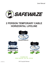
requires a specic amount of sag (based on span length) to function properly. Figure
10 on Page 12 indicates the proper sag for the system based upon span lengths.
Step 4. Ensure Plate Bolt Knob is Securely Tightened
Rotate the Locking Knob in a clockwise direction after tensioning rope until securely
tightened (See Figure 7F). Ensure Plate Bolt Knob is tightened prior to each use.
Attachment O-Ring for User (Lanyard)
Rope
Rope Tensioner
Carabiner
Carabiner
Swivel
Cross-Arm Strap
Typical Installation
Max. 100 Ft Span Length
Use this nut with help
of 24mm spanner to provide
appropriate tension to
the rope with minimum
possible sag
ANSI Z359.1
CAREFULLY READ
THE INSTRUCTION
MANUAL BEFORE
USING THIS PRODUCT
Ref.: PN 3001A
Batch No:12 18
Label Cover
FIGURE 6 - CROSS ARM STRAP INSTALLATION EXAMPLE
Cross Arm Strap System Installation
Step 1. Install Anchorage Connector
Wrap the Cross Arm Strap around the anchorage and pass the small D-ring end through
the large D-ring end. Wrap as many times as necessary to achieve desired length,
ensuring strap is wrapped at least twice around the end anchorage. A minimum of two
wraps around the end anchorage helps prevent sliding of the anchor straps during use.
Only connect to the small D-ring of the Cross Arm Strap. Refer to the Fall Clearance
Charts (Page 12, 13, and 14) for installation height variances.
Other approved anchorage connectors, which meet the 5,000 lbs. strength requirement,
may be used in place of the supplied FS810-6 Cross Arm Straps. See anchorage
connector user instructions for proper installation.

User Manual
V2.2023 Copyright Safewaze Page 10
Specications:
-Anodized Aluminum/Clear Zinc Steel
-Designed to be used with the Safewaze 4 Person Temporary Horizontal Lifeline System
-Weight: 3.6 lbs.
-16mm Double Braid Rope (16-plait cover and 8-plait core)
Meets OSHA 1926.502, 1910.140, 1910.66
FIGURE 7 - ROPE TENSIONER OPERATION
Use this nut with help
of 24mm spanner to provide
appropriate tension to
the rope with minimum
possible sag
ANSI Z359.1
CAREFULLY READ
THE INSTRUCTION
MANUAL BEFORE
USING THIS PRODUCT
Ref.: PN 3001A
Batch No:12 18
Ensure full
tightening of this nut
afert providing proper
tension to the lifeline
Perform following checks before each use:
• Ensure that the strength of the receiving structure
onto which device is anchored has breaking
strength greater than 5000lbs(23kN).
• For safe fall clearance from the ground refer to
the chart for relative span length/No of User’s
show in user instruction sheet.
• In case of any doubt arising about the safety of
the product, it should be replaced immediately on
consultation with an expert.
Use this nut with help
of 24mm spanner to provide
appropriate tension to
the rope with minimum
possible sag
ANSI Z359.1
CAREFULLY READ
THE INSTRUCTION
MANUAL BEFORE
USING THIS PRODUCT
Ref.: PN 3001A
Batch No:12 18
Front of Tensioner Rear of Tensioner
Use a Spanner / Adjustable
Wrench to tension.
Turn Wrench
counter clockwise
to put more tension on
the rope.
Tensioning Nut
Plate Bolt Knob
(Tightening)
Plate Bolt
Knob
Locking Lever
Closed
A
C D E
F
B

User Manual
V2.2023 Copyright Safewaze Page 11
FIGURE 9 - COMPONENTS
Max. 100 Ft Span Length
Use this nut with help
of 24mm spanner to provide
appropriate tension to
the rope with minimum
possible sag
ANSI Z359.1
CAREFULLY READ
THE INSTRUCTION
MANUAL BEFORE
USING THIS PRODUCT
Ref.: PN 3001A
Batch No:12 18
A
G
C
D
E
F
B
H
FIGURE 8 - RELEASING LIFELINE TENSION
If work operations are complete, work requires movement of HLL system to another location, or the
system needs to be uninstalled, the lifeline tension will need to be released. To release the tension:
Step 1. Ensure all equipment (SRLs / Energy Absorbing Lanyards), and users are disconnected from
the system prior to Step 2.
Step 2. Use a wrench or bar to open the locking lever to allow loosening of the lifeline.
Step 3. Loosen the tensioning nut, if necessary, with the spanner / adjustable wrench by turning the
tensioning nut clockwise until rope lifeline is loosened.
Step 4. The rope can be pulled through the tensioner by hand, if necessary, by holding the locking
lever in the disengaged position and pulling the rope through the tensioner.
The Safewaze 4 Person Temporary Horizontal Lifeline is designed as a temporary reusable
anchorage subsystem for the attachment of up to 4 Personal Fall Arrest systems. The 4 Person
Temporary Horizontal Lifeline subsystem is comprised of , 5/8” (16mm) diameter Polyester Double
Braid rope (Plait cover - Plait core), with a stitched thimble connection eye on one end and a rope
tensioning device on the other. The system also contains two self-closing, self-locking, ANSI Z359.12
compliant end attachment carabiners. One carabiner is attached to the thimble eye, and one is
attached to the rope tensioning device. The rope tensioning device is a painted steel tensioner
through which the Double Braid rope is threaded and then stitch terminated to prevent removal of the
rope from the tensioner.
A
B
C
D
E
F
G
Carabiner
O-Rings
Rope
Rope Tensioner
Swivel Connection
Cross Arm Strap
Anchorage
HLabel Cover
Ensure full
tightening of this nut
afert providing proper
tension to the lifeline
Perform following checks before each use:
• Ensure that the strength of the receiving structure
onto which device is anchored has breaking
strength greater than 5000lbs(23kN).
• For safe fall clearance from the ground refer to
the chart for relative span length/No of User’s
show in user instruction sheet.
• In case of any doubt arising about the safety of
the product, it should be replaced immediately on
consultation with an expert.
Rear of Tensioner Rear of Tensioner
Locking Lever
(Open)
Ensure full
tightening of this nut
afert providing proper
tension to the lifeline
Perform following checks before each use:
• Ensure that the strength of the receiving structure
onto which device is anchored has breaking
strength greater than 5000lbs(23kN).
• For safe fall clearance from the ground refer to
the chart for relative span length/No of User’s
show in user instruction sheet.
• In case of any doubt arising about the safety of
the product, it should be replaced immediately on
consultation with an expert.
AB

User Manual
V2.2023 Copyright Safewaze Page 12
FIGURE 10 - HLL SAG DISTANCES
1
0
2
3
4
5
6
7
8
9
10
11
12
13
10 20 30 40 50 60 70 80 90 100
Midpoint Span Sag (Inches)
HLL Span Length (Feet)
Incorrect Sag - Do Not Use
Correct Sag - OK For Use
Use this nut with help
of 24mm spanner to provide
appropriate tension to
the rope with minimum
possible sag
ANSI Z359.1
CAREFULLY READ
THE INSTRUCTION
MANUAL BEFORE
USING THIS PRODUCT
Ref.: PN 3001A
Batch No:12 18
Span Length
Midpoint
Sag
Span Length
(Feet)
Sag at Midpoint
(Inches)
10’ 1.0”
20’ 1.3”
30’ 1.7”
40’ 2.3”
50’ 3.1”
60’ 4.1”
70’ 5.5”
80’ 7.2”
90’ 9.5”
100’ 13.0”

User Manual
V2.2023 Copyright Safewaze Page 13
10.0 Fall Clearance Charts
A
FALL-ARREST
Use this nut with help
of 24mm spanner to provide
appropriate tension to
the rope with minimum
possible sag
ANSI Z359.1
CAREFULLY READ
THE INSTRUCTION
MANUAL BEFORE
USING THIS PRODUCT
Ref.: PN 3001A
Batch No:12 18
6 ft. Energy Absorbing Lanyard Fall
Clearance Chart
(2 Users)
420 lbs. Max Capacity per User
6 ft. Energy Absorbing Lanyard
Fall Clearance Chart
(4 Users)
310 lbs. Max Capacity per User
0-30
(0-9.14)
31-40
(9.44-12.20)
41-50
(12.50-15.24)
51-60
(15.54-18.28)
61-70
(18.60-21.33)
71-80
(21.64-24.38)
81-90
(24.68-27.43)
91-100
(27.73-30.48)
0 1 2 3 4 5 6
Freefall Distance in Feet
Span Length in Feet (m)
32.5
(9.90)
32.5
(9.90)
34.5
(10.51)
34.5
(10.51)
35.5
(10.82)
35.5
(10.82)
22.0
(6.70)
23.5
(7.16)
26.0
(7.92)
27.5
(8.38)
36.5
(11.12)
36.5
(11.12)
36.5
(11.12)
23.0
(7.01)
24.5
(7.46)
27.0
(8.22)
27.0
(8.22)
28.5
(8.68)
28.5
(8.68)
33.5
(10.21)
33.5
(10.21)
37.5
(11.43)
37.5
(11.43)
24.0
(7.31)
25.5
(7.77)
28.0
(8.53)
28.0
(8.53)
29.5
(8.99)
29.5
(8.99)
31.0
(9.44)
31.0
(9.44)
38.5
(11.73)
38.5
(11.73)
37.5
(11.43)
38.5
(11.73)
25.0
(7.62)
26.5
(8.07)
29.0
(8.83)
30.5
(9.29)
32.0
(9.75)
32.0
(9.75)
39.5
(12.03)
26.0
(7.92)
27.5
(8.38)
30.0
(9.14)
30.0
(9.14)
31.5
(9.60)
34.0
(10.36)
35.0
(10.66)
36.0
(10.97)
33.0
(10.05)
40.5
(12.34)
39.5
(12.03)
40.5
(12.34)
41.5
(12.64)
42.5
(12.95)
0-30
(0-9.14)
31-40
(9.44-12.20)
41-50
(12.50-15.24)
51-60
(15.54-18.28)
61-70
(18.60-21.33)
71-80
(21.64-24.38)
81-90
(24.68-27.43)
91-100
(27.73-30.48)
0 1 2 3 4 5 6
Freefall Distance in Feet
Span Length in Feet (m)
17
(5.18)
18.5
(5.63)
20.0
(6.09)
21.5
(6.55)
24.0
(7.31)
25.5
(7.77)
27.0
(8.22)
29.0
(8.83)
18.0
(5.48)
19.5
(5.94)
21.0
(6.40)
22.5
(6.85)
25.0
(7.62)
26.5
(8.07)
28.0
(8.53)
30.0
(9.14)
19.0
(5.79)
20.5
(6.24)
22.0
(6.70)
23.5
(7.16)
26.0
(7.92)
27.5
(8.38)
29.0
(8.83)
31.0
(9.44)
20.0
(6.09)
21.5
(6.55)
23.0
(7.01)
24.5
(7.46)
27.0
(8.22)
28.5
(8.68)
30.0
(9.14)
32.0
(9.75)
21.0
(6.40)
22.5
(6.85)
24.0
(7.31)
25.5
(7.77)
28.0
(8.53)
29.5
(8.99)
31.0
(9.44)
33.0
(10.05)
22.0
(6.70)
23.5
(7.16)
25.0
(7.62)
26.5
(8.07)
29.0
(8.83)
30.5
(9.29)
32.0
(9.75)
34.0
(10.36)
23.0
(7.01)
24.5
(7.46)
26
(7.92)
27.5
(8.38)
30.0
(9.14)
31.5
(9.60)
33.0
(10.05)
35.0
(10.66)

User Manual
V2.2023 Copyright Safewaze Page 14
Class A SRL Fall Clearance Chart Class B SRL Fall Clearance Chart
10.1 Fall Clearance Charts
Span Length In
Feet
(m)
Fall Clearance with
SafeWaze SRD in
Feet
(m)
Fall Clearance with
SafeWaze SRD in
Feet
(m)
SafeWaze Required Fall Clearance for Up to 4 Users
Maximum Span 100 ft.
0-30
(0-9.14)
31-40
(9.44-12.20)
41-50
(12.50-15.24)
51-60
(15.54-18.28)
61-70
(18.60-21.33)
71-80
(21.64-24.38)
81-90
(24.68-27.43)
91-100
(27.73-30.48)
ONE USER TWO USERS
10.0
(3.04)
11.0
(3.35)
13.0
(3.96)
14.0
(4.26)
16.0
(4.87)
17
(5.18)
19.0
(5.79)
20.0
(6.09)
11.0
(3.35)
12.0
(3.65)
14.0
(4.26)
15.0
(4.57)
17.0
(5.18)
18.0
(5.48)
20.0
(6.09)
21.0
(6.40)
Fall Clearance with
SafeWaze SRD in
Feet
(m)
Fall Clearance with
SafeWaze SRD in
Feet
(m)
THREE USERS FOUR USERS
12.0
(3.65)
13.0
(3.96)
15.0
(4.57)
16.0
(4.87)
18
(5.48)
19.0
(5.79)
21.0
(6.40)
22.0
(6.70)
13.0
(3.96)
14.0
(4.26)
16.0
(4.87)
17.0
(5.18)
19.0
(5.79)
20.0
(6.09)
22.0
(6.70)
23.0
(7.01)
Span Length In
Feet
(m)
Fall Clearance with
SafeWaze SRD in
Feet
(m)
Fall Clearance with
SafeWaze SRD in
Feet
(m)
SafeWaze Required Fall Clearance for Up to 4 Users
Maximum Span 100 ft.
0-30
(0-9.14)
31-40
(9.44-12.20)
41-50
(12.50-15.24)
51-60
(15.54-18.28)
61-70
(18.60-21.33)
71-80
(21.64-24.38)
81-90
(24.68-27.43)
91-100
(27.73-30.48)
ONE USER TWO USERS
12.5
(3.81)
13.5
(4.11)
15.5
(4.72)
16.5
(5.02)
18.5
(5.63)
19.5
(5.94)
21.5
(6.55)
22.5
(6.85)
13.5
(4.11)
14.5
(4.41)
16.5
(5.02)
17.5
(5.33)
19.5
(5.94)
20.5
(6.24)
22.5
(6.85)
23.5
(7.16)
Fall Clearance with
SafeWaze SRD in
Feet
(m)
Fall Clearance with
SafeWaze SRD in
Feet
(m)
THREE USERS FOUR USERS
14.5
(4.41)
15.5
(4.72)
17.5
(5.33)
18.5
(5.63)
20.5
(6.24)
21.5
(6.55)
23.5
(7.16)
24.5
(7.46)
15.5
(4.72)
16.5
(5.02)
18.5
(5.63)
19.5
(5.94)
21.5
(6.55)
22.5
(6.85)
24.5
(7.46)
25.5
(7.77)
A
FALL-ARREST
Use this nut with help
of 24mm spanner to provide
appropriate tension to
the rope with minimum
possible sag
ANSI Z359.1
CAREFULLY READ
THE INSTRUCTION
MANUAL BEFORE
USING THIS PRODUCT
Ref.: PN 3001A
Batch No:12 18
WWW.SAFEWAZE.COM
SELF RETRACTING LANYARD
SELF RETRACTING LANYARD
ANSI Z359.14 & ANSI A10.32
OSHA 1910.66 & OSHA 1926.502
Fall Arrest Systems • Confined Space • Engineering • Rescue Systems
6’
6’
Overhead SRL Usage
Fall Clearance Chart
(1 To 4 Users)
**THESE CLEARANCE CHARTS REQUIRE THAT THE SRL IS OVER THE HEAD OF THE WORKER WHEN
ATTACHED TO THE HORIZONTAL LIFELINE

User Manual
V2.2023 Copyright Safewaze Page 15
A
FALL-ARREST
WWW.SAFEWAZE.COM
SELF RETRACTING LANYARD
SELF RETRACTING LANYARD
ANSI Z359.14 & ANSI A10.32
OSHA 1910.66 & OSHA 1926.502
Fall Arrest Systems • Confined Space • Engineering • Rescue Systems
6’
6’
Use this nut with help
of 24mm spanner to provide
appropriate tension to
the rope with minimum
possible sag
ANSI Z359.1
CAREFULLY READ
THE INSTRUCTION
MANUAL BEFORE
USING THIS PRODUCT
Ref.: PN 3001A
Batch No:12 18
Personal SRL Usage
At or Below Dorsal D-ring Height
Fall Clearance Chart
0-30
(0-9.14)
31-40
(9.44-12.20)
41-50
(12.50-15.24)
51-60
(15.54-18.28)
61-70
(18.60-21.33)
71-80
(21.64-24.38)
81-90
(24.68-27.43)
91-100
(27.73-30.48)
0 1 2 3 4 5
Freefall Distance in Feet
THREE TO FOUR USERS
Span Length in Feet (m)
17
(5.18)
18.5
(5.63)
20.0
(6.09)
21.5
(6.55)
24.0
(7.31)
25.5
(7.77)
27.0
(8.22)
29.0
(8.83)
18.0
(5.48)
19.5
(5.94)
21.0
(6.40)
22.5
(6.85)
25.0
(7.62)
26.5
(8.07)
28.0
(8.53)
30.0
(9.14)
19.0
(5.79)
20.5
(6.24)
22.0
(6.70)
23.5
(7.16)
26.0
(7.92)
27.5
(8.38)
29.0
(8.83)
31.0
(9.44)
20.0
(6.09)
21.5
(6.55)
23.0
(7.01)
24.5
(7.46)
27.0
(8.22)
28.5
(8.68)
30.0
(9.14)
32.0
(9.75)
21.0
(6.40)
22.5
(6.85)
24.0
(7.31)
25.5
(7.77)
28.0
(8.53)
29.5
(8.99)
31.0
(9.44)
33.0
(10.05)
22.0
(6.70)
23.5
(7.16)
25.0
(7.62)
26.5
(8.07)
29.0
(8.83)
30.5
(9.29)
32.0
(9.75)
34.0
(10.36)
10.2 Fall Clearance Charts
0-30
(0-9.14)
31-40
(9.44-12.20)
41-50
(12.50-15.24)
51-60
(15.54-18.28)
61-70
(18.60-21.33)
71-80
(21.64-24.38)
81-90
(24.68-27.43)
91-100
(27.73-30.48)
0 1 2 3 4 5
Freefall Distance in Feet
ONE USER
Span Length in Feet (m)
9.5
(2.90)
10.5
(3.20)
11.5
(3.50)
13.0
(3.96)
14.0
(4.30)
15.5
(4.72)
17.0
(5.20)
18.0
(5.48)
11.0
(3.35)
12.0
(3.65)
13.0
(3.96)
14.5
(4.41)
15.5
(4.72)
17.0
(5.18)
19.0
(5.79)
20.5
(6.24)
12.5
(3.81)
13.5
(4.11)
14.5
(4.41)
16.0
(4.87)
17.0
(5.18)
18.5
(5.63)
21.0
(6.40)
22.5
(6.85)
13.5
(4.11)
15.5
(4.72)
17.0
(5.18)
18.0
(5.48)
19.5
(5.94)
21.0
(6.40)
22.5
(6.85)
25.0
(7.62)
15.0
(4.57)
17.0
(5.18)
18.5
(5.63)
19.5
(5.94)
21.0
(6.40)
22.5
(6.85)
24.0
(7.31)
27.0
(8.22)
16.5
(5.02)
18.5
(5.63)
20.0
(6.09)
21.5
(6.55)
23.0
(7.01)
24.0
(7.31)
26.0
(7.92)
28.5
(8.68)
0-30
(0-9.14)
31-40
(9.44-12.20)
41-50
(12.50-15.24)
51-60
(15.54-18.28)
61-70
(18.60-21.33)
71-80
(21.64-24.38)
81-90
(24.68-27.43)
91-100
(27.73-30.48)
0 1 2 3 4 5
Freefall Distance in Feet
TWO USERS
Span Length in Feet (m)
14
(4.26)
14.5
(4.41)
15.5
(4.72)
17.5
(6.55)
19.5
(7.31)
21.5
(7.77)
23.0
(8.22)
25.0
(8.83)
15.0
(4.57)
16.5
(5.02)
17.5
(5.33)
19.0
(5.79)
21.0
(6.40)
22.5
(6.85)
24.0
(7.31)
26.5
(8.07)
16.5
(5.02)
18.0
(5.48)
19.0
(5.79)
21.0
(6.40)
22.5
(6.85)
24.0
(7.31)
26.0
(7.92)
27.5
(8.38)
18.0
(5.48)
19.5
(5.94)
21.0
(6.40)
22.5
(6.85)
24.5
(7.46)
26.0
(7.92)
28.0
(8.53)
29.5
(8.99)
19.5
(5.94)
21.0
(6.40)
23.0
(7.01)
24.0
(7.31)
25.5
(7.77)
27.0
(8.22)
29.0
(8.83)
30.5
(9.29)
21.0
(6.40)
23.0
(7.01)
25.0
(7.62)
26.5
(8.07)
27.5
(8.38)
28.5
(8.68)
30.0
(9.14)
31.5
(9.60)

User Manual
V2.2023 Copyright Safewaze Page 16
Maintenance
Any Safewaze 4 Person Temporary Horizontal Lifeline components requiring
maintenance must be tagged “unusable” and removed from service.
Cleaning maintenance may be performed by the user.
Repairs to the product may only be made by the manufacturer or entities authorized in
writing by the manufacturer.
THIS DEVICE MUST ONLY BE SERVICED BY A TRAINED AND COMPETENT INDIVIDUAL!
NEVER ATTEMPT TO SERVICE THIS UNIT OR TAMPER WITH ITS FUNCTION IN ANY WAY!
Storage
When not installed, the Safewaze Horizontal Lifeline should be stored in a cool, dry
place out of direct sunlight. Do not store in areas where damage from environmental
factors such as heat, light, excessive moisture, oil, chemicals and their vapors, or other
degrading elements may be present. Do not store damaged equipment, or equipment
in need of maintenance, in the same area as equipment approved for use. Equipment
that has been stored for an extended period must be inspected as described in these
User Instructions prior to use.
11.0 Inspection and Maintenance
Inspection
Inspect the device and components for corrosion and/or damage.
Check the Housing Plates for signs of distortion.
Inspect both the webbing of Cross Arm Straps (if being used) and Rope for cuts,
abrasions and contamination.
Check carabiners for proper operation, signs of corrosion, distortion, or damage.
Ensure that no load indicators have deployed on any connecting device intended for
use with the HLL.
Frequency
All components of the Safewaze 4 Person Temporary Horizontal Lifeline must be
inspected prior to each use, and annually by a “competent person” (other than the
user), as dened by OSHA.
Criteria
If inspection reveals any defect, inadequate maintenance, or unsafe condition, remove
from service until a “qualied person” as dened by OSHA 1926.32(m) can determine
the need for authorized repair or disposal.

User Manual
V2.2023 Copyright Safewaze
12.0 Labels
WARNING
Manufacturer’s instructions supplied with this product at time of shipment must be
read and understood prior to use. Ensure Horizontal Lifeline is installed at an
elevations which will limit Free Falls to a maximum of 6 feet when using Energy
Absorbing Lanyards, and installed overhead when using Self Retracting Lifelines.
This equipment must be installed under the supervision of a Qualified Person.
Inspect all connections prior to use and verify connecting components are installed
correctly. Failure to make secure connections could result in serious injury or death.
Not flame or heat resistant. Avoid contact with sharp and abrasive edges. Caution
should be taken using this equipment near Hazardous Thermal, Electrical, or
Chemical Sources. Equipment exposed to fall arrest forces should be immediately
removed from service. Alteration or misuse of this product, or failure to follow
instructions could lead to serious injury or death. DO NOT REMOVE THIS LABEL.
019702
Page 17
13.0 Inspection Log
DATE CONDITION OF SYSTEM INSPECTED BY:

User Manual
V2.2023 Copyright Safewaze Page 18
WARRANTY
Safewaze
225 Wilshire Ave SW
Concord, NC 28025
PHONE: 1-800-230-0319
FAX: 1-704-262-9051
EMAIL: [email protected]
Web: safewaze.com

Manual del usuario
220-00006
Cumple con las normas
1926.502, 1910.140, 1910.66
V2.2023 Copyright Safewaze
LÍNEA SALVAVIDAS HORIZONTAL TEMPORAL
DE CUERDA DE TRENZA DOBLE
PARA 4 PERSONAS
/