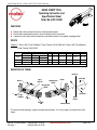
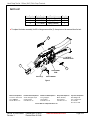
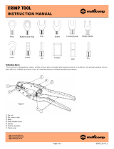
Molex 63811-0300 is a hand crimp tool designed for crimping 1.25mm (.049") pitch crimp terminals. It is ideally suited for end users due to its small handle spread and user-friendly terminal locator wire stop. The ratchet mechanism ensures consistent performance, and the adjustable crimp force allows for customization to suit different crimping needs. The tool is suitable for crimping PicoBlade™ crimp terminals and board-in crimp terminals with wire sizes ranging from 26-28 AWG and insulation diameters from 0.67-1.00 mm.
Molex 63811-0300 is a hand crimp tool designed for crimping 1.25mm (.049") pitch crimp terminals. It is ideally suited for end users due to its small handle spread and user-friendly terminal locator wire stop. The ratchet mechanism ensures consistent performance, and the adjustable crimp force allows for customization to suit different crimping needs. The tool is suitable for crimping PicoBlade™ crimp terminals and board-in crimp terminals with wire sizes ranging from 26-28 AWG and insulation diameters from 0.67-1.00 mm.


-
 1
1
-
 2
2
-
 3
3
-
 4
4
-
 5
5


Molex 63811-0300 is a hand crimp tool designed for crimping 1.25mm (.049") pitch crimp terminals. It is ideally suited for end users due to its small handle spread and user-friendly terminal locator wire stop. The ratchet mechanism ensures consistent performance, and the adjustable crimp force allows for customization to suit different crimping needs. The tool is suitable for crimping PicoBlade™ crimp terminals and board-in crimp terminals with wire sizes ranging from 26-28 AWG and insulation diameters from 0.67-1.00 mm.
Ask a question and I''ll find the answer in the document
Finding information in a document is now easier with AI
Related papers
-
Molex CS 150 User manual
-
-
Molex 207129 Series User manual
-
-
-
Molex 0151341205 Assembly Instructions
-
-
-
-
Other documents
-
Beta 1752 Operating instructions
-
 Keeper 05514 Operating instructions
-
3M Scotchlok™ Hardened Steel Ratchet Tool TR-482, crimps nylon, vinyl-insulated, butted- or brazed-seam terminals and connectors User guide
-
 multicomp pro KST2000D-1322 Operating instructions
-
Amphenol 957-7610 Assembly Procedure
-
Mitsubishi Electric MR-MC200 Series Owner's manual
-
GE Tempo Interlocking Solution User manual

