Page is loading ...

RO ALK + UV System
Installation Manual
Cuomer Support 1-800-992-8876

RO Alkaline + UV
Overall System Connections
Connection Points
A to B Connect the RED Tubing to the Feed Water
Adapter Valve (point A), then to the hole marked as
“IN” on the Leak Stop Valve (point B).
C to D Connect the WHITE Tubing to the hole
marked as “OUT” on the Leak Stop Valve (point C),
then to the Sediment Filter Housing’s Male Elbow
Fitting (point D).
E to F Connect the BLACK Tubing to the Flow
Restrictor side indicated by the arrow on the Restrictor
(point E), then to the Drain Saddle (point F).
G to H Connect the YELLOW Tubing to the Inline
Post Carbon Filter’s Stem Run Tee (point G), then to
the Water Storage Tank’s Tank Valve (point H).
I to J Connect the BLUE Tubing to the Stem Elbow at
the end of the Inline Post Carbon Filter (point I), then
to your RO Faucet connection (point J).
Your drinking water is going to be healthier and taste better from now on, and nothing
makes us happier. Getting started is a breeze— most of your Reverse Osmosis System is
already assembled and every connection is color coded. We’ve marked where the colored
tubes will go with matching colored plugs in each tting.
We know life isn’t always so simple though. If you have questions during your setup we
can help. Just give us a call during normal business hours at: 1-800-992-8876
For Installation Videos go to:
www.youtube.com/c/ExpressWaterVideo


READ THIS FIRST
Please pay attention to the following inallation and safety recommendations:
- Read the inallation manual before inalling this syem.
NOTE! Please make sure your inallation location has enough room for the RO Syem and Water Storage Tank.
Make sure your inall location has access to a power outlet for the Ultraviolet Sterilizer.
Incoming Water
Incoming water pressure mu be between 40 PSI and 80 PSI. If your water pressure is under 40 PSI you
will need a booer pump for your syem. If your water pressure is above 80 PSI you will need a pressure
regulator for your syem. Te your water pressure occasionally to make sure the syem is performing. If your
water is microbiologically unsafe or of unknown quality do not use this syem without adequate disinfection
before or after the syem. Extremely hot or cold incoming water will damage the syem and cannot be used.
Leaks
The Leak Stop Valve mu be inalled. Inspect all connections after the inallation to make sure no leaks
occur, wait until after the syem is pressurized (turned on) to inspect again. Check syem occasionally
after inallation or maintenance to make sure no leaks have developed. Inall the syem in a location with
adequate drainage.
General
This RO Syem unit is for climate controlled indoor use only. Exposure to overly high or low temperature
ranges will damage the unit. Follow all of your ate and local laws and codes regarding plumbing even if they
dier from what is ated in this manual. If your ate law requires it or you prefer to we recommend using
a professional licensed inaller or plumber who meets the requirements of this syem. All O-Rings, ttings,
lter caniers, and teon tape wear out after a certain period of time. The lifetime of your components are
subject to change with the quality of the water supplied. Do not handle an unwrapped lter directly with your
bare hands as this can cause early lter failure. Use appropriate eye and face protection when performing any
drilling. The Ultraviolet Sterilizer requires access to a 110V power outlet; make sure you have safe access to
power for this syem. Do not look directly at UV Bulb without protection!
Maintenance
The owner/user is obligated to properly maintain the RO Syem when necessary, at lea every 1 year. This
includes the following:
- Replace the O-rings on the lter housings, membrane housing, ttings, and lter cartridges.
- Replace any connectors and lter housings with proper replacement parts.
- Sanitize your syem as often as needed (how often changes with the prole of your area’s incoming water).
- Always use proper replacement lter cartridges with the correct size and length replacements.
- Replace the Teon Tape on all threaded connections and ttings.
Copyright © 2020 by Express Water Inc.
All rights reserved. No part of this publication may be reproduced, diributed, or transmitted in any form or by any
means, including photocopying, recording, or other electronic or mechanical methods, without the prior written
permission of the publisher, except in the case of brief quotations embodied in critical reviews and certain other
noncommercial uses permitted by copyright law.
Conditions

Table of Contents
Introduction
Inallation Notes
Components Li
Syem Components
Tubing Quick Connect Guide
Inallation
Feed Water Adapter Valve
RO Faucet
Drain Saddle
Housing Assembly
Elbow Fitting Inallation
Gauge Inallation
Leak Stop Valve
Water Storage Tank
Ultraviolet Sterilizer Inallation
Syem Connections
Syem Startup
Syem Maintenance
Filter Change Inruction
How to Sanitize your RO Drinking Water Syem
Troubleshooting
FAQ
Express Water Accessories and Upgrades
Warranty
Page 7
Page 8
Page 8
Page 10
Page 11
Page 12
Page 14
Page 16
Page 17
Page 18
Page 18
Page 19
Page 20
Page 21
Page 22
Page 23
Page 23
Page 24
Page 26
Page 27
Page 28
Page 30
Page 31


7
Introduction
You have purchased the ne residential Reverse Osmosis Alkaline + Ultraviolet Drinking Water
Syem available for your home. When properly maintained this syem will provide you with years of
great taing pure drinking water and trouble-free service.
Please make sure to thoroughly read the inallation manual and become familiar with the tools needed
before proceeding with the inallation.
Also, please make sure to inspect the package for any missing components or shipping damages.
If you nd any issues or have queions please contact Express Water at 1-800-992-8876
Monday - Friday 10 am to 5 pm PST
Replacements Table
Replacement Filters
Express Water oers replacement lters for both the ROALKUV5D (50GPD Syem) and ROALKUV10D
(100GPD Syem) Reverse Osmosis Water Filtration Syems. For purchasing information for replacement
lters, please visit our website at www.ExpressWater.com

8
Inallation Notes
Tools Required
Before you begin please make sure you have all of the following tools ready to use:
- Box Cutter
- Phillips-Head Screwdriver
- Power Drill
- 1/4” Drill Bit (for Drain Saddle Valve)
- 1/2” Drill Bit (for RO Faucet)
- Adjuable Wrench
Components Li
Your new Reverse Osmosis Water Syem should include the following items.
If any item is missing please contact Express Water.
Please take a few moments to check all the following components:
5 ft Yellow 2 ft White
5 ft Red 5 ft Blue 5 ft Black
Color Coded Tube 1/4” OD Drain Saddle Package
Foam Gasket2 Drain Clamp Halves
2 Nuts
2 Bolts
Connections
Faucet
Adapter
Male
Elbow
Male Elbow
with Red Plug
2
Screws
Locking Clip
Bag
Tank
Valve
Feed Water Adapter Valve Teon Tape Filter Housing Wrench

9
Leak Stop Valve Components
Leak Stop Valve
3 Replacement Pads
2 Mounting Screws
Screws
Pads
Leak Stop Valve
RO Storage Tank
Water Storage Tank
Tank Stand
NOTE!
In the package you will nd the Tank Stand
screwed to the top of the tank. Unscrew it
and place it underneath for a eady position.
Storage Tank
Tank Stand
Thread
Air Valve
RO Faucet Kit Components
1
4
7
2
5
8
3
6
9
Faucet Design and
Accesories May Vary
1. Rubber Washer (Large)
2. Base Plate
3. Plaic Washer
4. Rubber Washer (Small)
5. Lock Washer
6. Hex Nut
7. Compression Nut
8. Insert
9. Sleeve
UV Sterilizer
Quartz Tube
UV O-Ring
UV Housing
UV Bulb
UV Balla

10
Carbon
Filter
GAC
Filter
Sediment
Filter
Filter Housing
RO Unit
Top Part Components
Inline Po Carbon Filter - FLTIN01PKQ
Ultraviolet Filter - FLTUV110BCH
Alkaline Filter - FLTALK10Q
RO Membrane Filter - FLTMEME50 / FLTMEME100
Bottom Part Components
Filter Housings - PRTHSF10DB14
Sediment Filter - FLTSED0501
GAC Filter - FLTGAC0501
Carbon Block Filter - FLTCAR0501C
Syem Components
RO Membrane
Ultraviolet Filter
Inline Po Carbon Filter
Alkaline Filter
1. Feed Water Adapter Valve
2. Leak Stop Valve
3. Sediment Water Filter
4. GAC Filter
5. Carbon Block Filter
6. Male Elbow 1/4”
7. Automatic Shut-O Valve
8. Male Elbow 1/8”
9. RO Membrane Housing
10. Check Valve
11. Drain Flow Restrictor
12. Drain Saddle
13. Stem Elbow
14. Alkaline Filter
15. Ultraviolet Sterilizer
16. Stem Run Tee
17. Inline Post Carbon Filter
18. Tank Valve
19. Water Storage Tank
20. Tank Stand
21. QC Faucet Connector
22. Faucet

11
Tubing Quick Connect Guide
To Cut Tubing
Make your cuts again a at cutting surface with a razor blade, or use a handheld tube cutter. Any cuts to
your Tubing mu be perfectly raight.
NOTE!
Improperly cut Tubing may leak water or fail to lock into Fittings.
Wait until all elements of your RO Syem are in their nal locations before cutting your Tubing.
Make sure you measure the length you will need before cutting.
Attach Tubing
Push Tubing in raight and level with the
Collet. The Tubing will go 5/8ths of an inch
into the Collet before the lock is activated.
Pull out on the Tube to make sure the lock
has activated and the Tubing is secure.
NOTE! Once connected, make sure to
check tubing is secure.
5/8”
5/8”
Insert or Remove Locking Clips
To lock a Tube in place make sure the
Tubing is fully inserted then slide the open
end of the Clip between the Collet and Fit-
ting. The Clip mu be removed before the
Tubing can be removed. To remove the Clip
pull away until it slides out from between
the Collet and Fitting.
Unlocked Locked
The tubing in your RO Syem uses a Quick Connect locking mechanism to
lock the Color Coded Tubing in place. Be careful not to damage your tubing
as you unpack it.
NOTE!
Make sure to remove any plugs before attempting to insert tubing.
Plug
Collet
Locking
Clip
Fitting
Release Tubing/Plugs
If there is a Locking Clip on the Collet it mu
be removed before the Tubing can be released.
Push and hold the Collet in to release the lock
while pulling out on the Tube/Plugs.
NOTE! Collet mu be held down while
pulling up on the tube to release the tube.
Hold
Down
Pull
Up

12
Feed Water Adapter Valve
NOTE!
If your Cold Water Valve is too old or weak to connect
to directly Option A you can connect at the top of the
line where the faucet connects Option B (if applicable,
some sinks do not have this connection point).
CAUTION!
The water supply to the unit MUST be from
the COLD WATER LINE. Using HOT WATER will
severely damage your RO Syem.
Do Not Connect To
Hot Water Line!
NOTE!
On single-handle faucets the hot water may
have to be turned o to prevent hot water
crossover (only during your r inallation).
If water ill continues to come out of the faucet with
the Cold Water Valve turned o, then the main water
supply mu be turned o as well.
1. Locate the Cold Water Valve underneath the sink
and turn it o completely. Next, open the cold water
handle on your sink to release any pressure by expelling
any exiing water. Check to make sure the water has
opped owing completely before proceeding.
B
A
Hot Water Line
Cold Water Line

13
2. As shown below, the Feed Water Adapter Valve can be used for 3/8” or 1/2” feed line plumbing.
Next, use an adjuable wrench to secure the Adapter Valve either directly to the Cold Water Valve
Option A or further up in the line before the faucet Option B (if applicable).
Make sure your Adapter Valve is in the closed position when inalling it.
Using the Feed Water Adapter Valve
During inallation leave your Feed Water Adapter Valve in the “CLOSED” position until Syem Startup.
The Feed Water Adapter Valve controls all water coming into your RO Syem. If for any reason you need to
op incoming water turn the Feed Water Adapter Valve to the “CLOSED” position. Always turn this valve o
before replacing lters, if a leak is discovered, or when shutting down the syem.
CLOSEDOPEN
WARNING!
INCOMING WATER PRESSURE
SHOULD NOT EXCEED 80 PSI
NOTE!
Do Not Use Teon Tape!
Use your wrench to tighten the connection, be careful not to over tighten.
Simply switch the Adapter Nut
(see left image) from one side of
the Adapter Valve to the other.
3/8” Connection1/2” Connection
Adapter
Nut
Adapter
Nut

14
Stainless Steel Sink
1. Use a proper 1/2” drill bit (depending on your sink/counter material) to make a hole for your RO Faucet.
2. Insert the small rubber washer, then the base plate, then the large rubber washer (see image on next page)
onto the Threaded Faucet Stem at the base of the RO Faucet.Then put the Threaded Faucet Stem through the
newly drilled or pre-exiing hole. Make sure the RO Faucet sits in the center of your new or exiing hole.
3. Under the sink inall Plaic Washer, Lock Washer, and Hex Nut (see image on next page) onto the Thread-
ed Faucet Stem. Make sure they are inalled all the way up the em.
NOTE! You can use either connection type (A or B).
4. Faucet Connection Line
Connection Type A - Add the Compression Nut, with the
more open end facing outwards, and Sleeve (see image) to
the Blue Tubing near one of the ends. Add the Insert into the
opening at the same end of the Tubing, then bring this end
to the Threaded Faucet Stem. Screw the Compression Nut
onto the Threaded Faucet Stem with an adjuable wrench.
Be careful not to over tighten.
Connection Type B - Add the Faucet Adapter to one end
of the Blue Tubing. Screw the Faucet Adapter onto the
Threaded Faucet Stem.
RO Faucet
The RO Faucet may be inalled on any at surface. Check the underside of your inall location for interfer-
ence by making sure that drilling a hole will not damage any pipes or wiring underneath the countertop or
sink. Check to be sure there is enough room for the Threaded Faucet Stem.
NOTE! For drilling you mu use an appropriate drill bit and drilling method for the material of your sink
and counter top. Dierent drill bits are required for ainless eel, porcelain, granite, etc.
You may use an exiing hole in your counter or sink or drill a new hole (if using an exiing hole begin at
ep 2). Make sure the Base Plate is big enough to cover the hole you use.
Porcelain Sink
A proper porcelain 1/2” drill bit is rongly recommended to prevent chipping if you are drilling on a
porcelain sink. Drill slowly to avoid chipping during the initial cutting of the porcelain.
Insert
Sleeve
Compression
Nut
1/4” Blue Color
Tube
1/4” Blue Color
Tube
Faucet
Adapter

15
Open and Closed Position
Closed Open
Insert
Sleeve
Connection
Type A
Compression Nut
Connection
Type B
Faucet Adapter
1/4”Blue
Color Tube
Base Plate
Plastic Washer
Lock Washer
Hex Nut
Large Rubber Washer
(If Applied)
Small Rubber Washer
(If Applied)
Counter Top
Threaded
Faucet
Stem
*Faucet Design May Vary

16
OK
Mount Drain Saddle
at either location
Drain Saddle
The Drain Saddle is used to connect the Black Drain Line to the drain pipe under the sink. The Drain Saddle
is designed to t around a andard 1.5 inch OD (outer diameter) drain pipe. The Drain Saddle should
always be inalled above (before) the P-Trap and on a raight vertical or horizontal section of pipe.
To avoid clogging the drain line with debris do not inall the Drain Saddle after the drain pipe meets a
garbage disposal or dishwasher drain. Refer to the image below to see ideal Drain Saddle locations.
1. Once you have found where your Drain Saddle will go on the Drain Pipe make a mark for the opening
there with a marker or pencil.
2. Use your drill and an appropriate 1/4 inch (6.35mm) drill bit to drill a hole at your mark. Be careful to drill
through one side of the pipe and abilize your pipes while drilling to avoid damaging them.
3. Find the half of the Drain Clamp with a hole in its center. Then remove the backing from the Foam Gasket
(the foam circle at the center of the Gasket is disposable). Make sure to align the Foam Gasket hole with the
Drain Clamp hole and ick the adhesive side of the Gasket to the inner wall of the Drain Clamp half.
4. Take the half of the Drain Clamp without the Foam Gasket and insert a nut into the recess on each side.
5. Position both halves of the Drain Clamp on the drain pipe with the clamp’s opening aligned over the
drilled hole. The Foam Gasket will be between the drain clamp and the drilled hole. Push your 1/4 inch drill
bit through both holes (the Drain Clamp hole and the hole in the Drain Pipe) and remove to verify that the
clamp is properly aligned with the hole you drilled.
6. Secure the Drain Clamp halves together in place on the Drain Pipe. Screw the bolts through the Drain
Clamp half with the Foam Gasket and into the half you inalled the nuts into. (Do not over tighten. Make sure
there is equal space on both sides between the Drain Clamp halves.)
X
WARNING!
Never mount there!
OK
OK
X
X
P-Trap
Garbage
Disposal
Nut
Black Tube/Drain Line
Foam Gasket
Drain
Clamp
Drain Pipe
1/4” Hole
Bolt
*Adjuable drain saddles are available if the saddle does not t your pipe

17
Housing Assembly
Prepare Prelters
Leave the lters wrapped until you need them. When inalling
be careful not to touch the lter portion with your hands.
Remove the plaic wrap from the 3 Filter Housings and and
them upright. Make sure each Housing has two O-Rings rmly
in place at the top of the Housing and in the Housing’s lower
groove.
NOTE!
Reference image to place
each of the prelters in the
correct order:
- the orange Sediment Filter
will be on the far right (under
the label “TO FEED”).
- the blue Carbon Block Filter
will be on the opposite side,
the far left.
- the green GAC Filter will be
in the center, between the
other two. The white washer
will be facing up for correct
placement.
Top Part of the Unit
Filter
Housing O-Rings
Filter Housing
3rd 2nd 1
1. The RO Membrane is already on the syem. To
make sure the cap is secure, tighten the RO Membrane
Housing Cap clockwise by Wrench or hand.
2. Use your hands to screw each Filter Housing onto
the RO Syem. Finish tightening each housing using
the lter wrench. DO NOT OVERTIGHTEN!
Attention
1
2

18
Elbow Fitting Inallation
Gauge Inallation
1. Screw a Male Elbow Fitting into the right-
mo Filter Housing (Sediment) marked “IN”.
Screw until tightened and the arm of the Elbow
is facing downward.
2. Secure the White Tubing into the Male Elbow
Fitting. Push hard enough on the tubing to
make sure the Quick Connect has locked
before moving on.
3. Screw the other Male Elbow Fitting (with red
plug) into the leftmo Filter Housing (Carbon
Block) marked “OUT”. Screw until tightened and
the arm of the Elbow is facing upwards at an 11
O’Clock angle (use the above image for reference).
4. Remove the Red Plug. Secure the Red
Tubing into the Male Elbow Fitting. Push hard
enough on the tubing to make sure the Quick
Connect has locked before moving on.
1. Put the end of the Pressure Gauge into one
of the top arms of the Stem Tee. Then, put the
Red Tubing into the opposite end as shown.
Both will go about 5/8ths inch into the tee to
secure.
2. Put the small bottom end of the Stem Tee into
the Male Elbow of the RO Membrane Cap. Use
Blue Locking Clips to secure all 3 connection
points as shown.
NOTE!
Not all RO Syems include a Pressure Gauge. If your syem does include a Gauge we will inall it now.

19
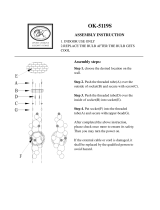
Leak Stop Valve
Note! Please avoid contact of any liquid to the compressed textile. Failure to do so will activate
the textile and shut the incoming water. Textile will not work if plaic wrap is not removed.
Please do not re-use Leak Stop pads once activated.
4. Take the plaic wrap o of the Compressed
Textile then place the Textile inside the Leak Stop
Valve as shown above. (You may wish to insert
the Compressed Textile after Syem Startup is
complete in case of early monitored leaks).
INOUT
Flow Closed Position
5. Turn the Stop Switch down and the
Leak Stop Valve is ready.
Red
Tube
White
Tube
INOUT
Flow Open Position
2. Position the Leak Stop Valve on the oor of the same
cabinet (so any leaking water will make contact with the
valve) beside the syem and use the two screws to secure
the Valve to the cabinet oor. (Place Leak Stop Valve in the
lowe possible location beside the RO Syem).
3. Connect one end of the Red Tubing into the Feed Water Adapter Valve and connect the other end
of the Red Tubing into the hole marked “IN” on the Leak Stop Valve. Then connect one end of the
White Tubing into the hole marked “OUT” on the Leak Stop Valve and connect the other end of the
White Tubing into the Male Elbow Fitting attached to the Sediment Filter Housing marked “IN”.
Red TubeWhite Tube
INOUT
1. Position the RO Syem in the
desired permanent location. Your
syem can be placed on its back
for space if needed.

20
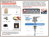
Water Storage Tank
NOTE! Do not tamper with the air valve on the lower side of
the Water Storage Tank. It has been preset at 7-10 PSI.
1. Open the Water Storage Tank box and unscrew the Tank Stand
from the threaded em at the top of the Tank.
2. Wrap the threaded em 8-10 times with Teon Tape.
3. Screw the Tank Valve onto the threaded em. Make sure it is
tight, but do not over tighten.
4. Place the Water Storage Tank near the RO Syem in the de-
sired location. The Tank can and up raight or lie on its side.
5. Connect the Yellow Tubing to the Stem Run Tee of the Inline
Po Carbon Filter, then to the Tank Valve (See I to J on Page 23).
6. Keep the Tank Valve in the Closed Position until Syem Startup.
NOTE! If 3-5 hours after artup your tank does not ll: Connect
the tank directly to the cold water supply (bypassing the RO Sys-
tem) and allow the tank to ll for about 1 minute. Then reconnect
to your syem as normal and empty the tank through faucet. This
will help activate the tank bladder.
NOTE! The Tank Valve only controls
water leaving the Water Storage Tank.
To op all incoming water use the
Feed Water Adapter Valve.
A. Tank Thread
B
A
C
B. Tank Valve
OPEN POSITION
C. Tank Stand
CLOSED POSITION
/