Page is loading ...

Dell Dimension 9200C Service Manual
file:///T|/htdocs/systems/dim9200C/en/SM_EN/index.htm[10/31/2012 8:07:07 AM]
Dell™ Dimension™ 9200C Service Manual
Before You Begin
About Your Computer
Technical Overview
Specifications
Troubleshooting
System Setup
Removing the Computer Cover
Removing and Installing Parts
Replacing the Computer Cover
Notes, Notices, and Cautions
NOTE: A NOTE indicates important information that helps you make better use of your computer.
NOTICE: A NOTICE indicates either potential damage to hardware or loss of data and tells you how to avoid the
problem.
CAUTION: A CAUTION indicates a potential for property damage, personal injury, or death.
Information in this document is subject to change without notice.
© 2006 Dell Inc. All rights reserved.
Reproduction in any manner whatsoever without the written permission of Dell Inc. is strictly forbidden.
Trademarks used in this text: Dell, the DELL logo, and Dimension are trademarks of Dell Inc.; Intel, Pentium, Intel SpeedStep, and Celeron are
registered trademarks of Intel Corporation; Microsoft and Windows are registered trademarks of Microsoft Corporation.
Other trademarks and trade names may be used in this document to refer to either the entities claiming the marks and names or their products.
Dell Inc. disclaims any proprietary interest in trademarks and trade names other than its own.
August 2006 Rev. A00

Before You Begin: Dell Dimension 9200C Service Manual
file:///T|/htdocs/systems/dim9200C/en/SM_EN/before.htm[10/31/2012 8:07:09 AM]
Back to Contents Page
Before You Begin
Dell™ Dimension™ 9200C Service Manual
Getting Started
Recommended Tools
Turning Off Your Computer
Before Working Inside Your Computer
Getting Started
This manual provides procedures for removing and replacing the components in your computer. Unless otherwise noted, each
procedure assumes that the following conditions exist:
You have performed the steps in Turning Off Your Computer and Before Working Inside Your Computer.
You have read the safety information in your Dell™ Product Information Guide.
A component can be replaced by performing the removal procedure in reverse order.
Recommended Tools
The procedures in this document may require the following tools:
Small flat-blade screwdriver
Phillips #0, #1, or #2 screwdriver
Flash BIOS update program (download from support.dell.com)
Turning Off Your Computer
NOTICE: To avoid losing data, save and close any open files and exit any open programs before you turn off your
computer.
1. Shut down the operating system:
a. Save and close any open files, exit any open programs, click the Start button, and then click Shutdown.
b. In the Shut Down Windows window, select Shut Down.
The computer turns off after the operating system shutdown process finishes.
2. Ensure that the computer and any attached devices are turned off. If your computer and attached devices did not
automatically turn off when you shut down your operating system, press and hold the power button for 4 seconds.
Before Working Inside Your Computer

Before You Begin: Dell Dimension 9200C Service Manual
file:///T|/htdocs/systems/dim9200C/en/SM_EN/before.htm[10/31/2012 8:07:09 AM]
Use the following safety guidelines to help protect your computer from potential damage and to help ensure your own
personal safety.
CAUTION: Before you begin any of the procedures in this section, follow the safety instructions in the
Product Information Guide.
CAUTION: Handle components and cards with care. Do not touch the components or contacts on a card.
Hold a card by its edges or by its metal mounting bracket. Hold a component such as a processor by its
edges, not by its pins.
NOTICE: Only a certified service technician should perform repairs on your computer. Damage due to servicing that is
not authorized by Dell is not covered by your warranty.
NOTICE: When you disconnect a cable, pull on its connector or on its strain-relief loop, not on the cable itself. Some
cables have a connector with locking tabs; if you are disconnecting this type of cable, press in on the locking tabs
before you disconnect the cable. As you pull connectors apart, keep them evenly aligned to avoid bending any
connector pins. Also, before you connect a cable, ensure that both connectors are correctly oriented and aligned.
NOTICE: To avoid damaging the computer, perform the following steps before you begin working inside the computer.
1. Follow the steps in Turning Off Your Computer
.
NOTICE: To disconnect a network cable, first unplug the cable from your computer and then unplug it from the
network port or device.
2. Disconnect any telephone or network cables from the computer.
3. Disconnect your computer and all attached devices from their electrical outlets, and then press the power button to
ground the system board.
CAUTION: To guard against electrical shock, always unplug your computer from the electrical outlet before
opening the cover.
4. Remove the computer cover (see Removing the Computer Cover
).
NOTICE: Before touching anything inside your computer, ground yourself by touching an unpainted metal surface,
such as the metal at the back of the computer. While you work, periodically touch an unpainted metal surface to
dissipate any static electricity that could harm internal components.
Back to Contents Page

About Your Computer: Dell Dimension 9200C Service Manual
file:///T|/htdocs/systems/dim9200C/en/SM_EN/about.htm[10/31/2012 8:07:13 AM]
Back to Contents Page
About Your Computer
Dell™ Dimension™ 9200C Service Manual
Front View
Back View
Front View
NOTE: The front panel door does not close when you are using certain Flash Media, IEEE 1394, USB, or headphone
connectors.
--
1 CD/DVD
drive eject
button
Press this button to eject a CD/DVD from the drive.
2 CD/DVD
drive
activity
light
The drive activity light is on when the computer reads data from the CD or
DVD drive.
3 USB 2.0
connectors
(2)
Use the front USB connectors for devices that you connect occasionally, such
as joysticks or cameras (see System Setup
for more information on booting
to a USB device).

About Your Computer: Dell Dimension 9200C Service Manual
file:///T|/htdocs/systems/dim9200C/en/SM_EN/about.htm[10/31/2012 8:07:13 AM]
It is recommended that you use the back USB connectors for devices that
typically remain connected, such as printers and keyboards.
4 IEEE 1394
connector
Attach high-speed serial multimedia devices, such as digital video cameras.
It is recommended that you use the back IEEE 1394 connector for devices
that typically remain connected, such as external hard drives and other
storage devices.
5 vents For adequate cooling, do not block any of the vents.
NOTICE: Ensure that there is a minimum of two inches of space between all
vents and any object near the vents.
NOTICE: Do not lift or carry the computer by the vents to avoid damage to
the computer.
NOTICE: Keep the vent area clean and dust free to ensure that the computer
is adequately ventilated. Use only a dry cloth to clean the vent area to avoid
water damage to the computer.
6 power
button
Press this button to turn on the computer.
NOTICE: To avoid losing data, do not use the power button to turn off the
computer. Instead, perform an operating system shutdown.
7 power light The power light illuminates and indicates different power states:
No light — The computer is turned off.
Steady green — The computer is in a normal operating state.
Blinking green — The computer is in a power-saving state.
Blinking or solid amber — See Power Problems in your computer
Owner's Manual.
8 front panel
door
release
button
Press this button to access the front panel connectors.
9 microphone
connector
Use the pink microphone connector to attach a personal computer
microphone for voice or musical input into a sound or telephony program.
On computers with a sound card, use the microphone connector on the card.
10 headphone
connector
Use the green headphone connector to attach headphones and most kinds of
speakers.
11 FlexBay Use the Flexbay for an optional floppy drive or Media Card Reader.
12 hard drive
activity
light
The hard drive activity light is on when the computer reads data from, or
writes data to the hard drive. The light might also be on when a device such
as a CD player is operating.
13 diagnostic
lights
For an explanation of the diagnostic light codes, see Diagnostic Lights
.
14 front panel
door
This panel covers the CD/DVD drive, the Media Card Reader, and the optional
floppy drive.
Back View

About Your Computer: Dell Dimension 9200C Service Manual
file:///T|/htdocs/systems/dim9200C/en/SM_EN/about.htm[10/31/2012 8:07:13 AM]
1 voltage selection switch (may not be
available on all computers)
See the safety instructions in the Product
Information Guide for more information.
2 power connector Insert the power cable.
3 back panel connectors Plug IEEE 1394, USB and other devices into the
appropriate connector.
4 card slots Access connectors for any installed PCI Express
cards.
Back Panel Connectors
1 link
integrity
light
Green — A good connection exists between a 10-Mbps network and the
computer.
Orange — A good connection exists between a 100-Mbps network and
the computer.
Off — The computer is not detecting a physical connection to the
network.

About Your Computer: Dell Dimension 9200C Service Manual
file:///T|/htdocs/systems/dim9200C/en/SM_EN/about.htm[10/31/2012 8:07:13 AM]
2 network
adapter
connector
To attach your computer to a network or broadband device, connect one end
of a network cable to either a network jack or your network or broadband
device. Connect the other end of the network cable to the network adapter
connector on the back panel of your computer. A click indicates that the
network cable has been securely attached.
NOTE: Do not plug a telephone cable into the network connector.
On computers with a network connector card, use the connector on the card.
It is recommended that you use Category 5 wiring and connectors for your
network. If you must use Category 3 wiring, force the network speed to 10
Mbps to ensure reliable operation.
3 network
activity
light
Flashes a yellow light when the computer is transmitting or receiving network
data. A high volume of network traffic may make this light appear to be in a
steady "on" state.
4 modem
connector
Use the modem connector to connect your computer to the Internet.
5 rear
surround
sound
connector
Use the black surround sound connector to attach multichannel-capable
speakers.
6 line-in
connector
Use the blue line-in connector to attach a record/playback device such as a
cassette player, CD player, or VCR.
On computers with a sound card, use the connector on the card.
7 line-out
connector
Use the green line-out connector to attach headphones and most speakers
with integrated amplifiers.
On computers with a sound card, use the connector on the card.
8 microphone Use the pink connector to attach a personal computer microphone for voice or
musical input into a sound or telephony program.
On computers with a sound card, use the microphone connector on the card.
9 side
surround
sound
connector
Use the grey surround sound connector to attach multichannel-capable
speakers.
10 center/LFE
connector
The LFE (Low Frequency Effects) Audio channel, found in digital surround
sound audio schemes, carries only low frequency information of 80 Hz and
below. The LFE channel drives a subwoofer to provide extremely low bass
extension. Systems not using subwoofers can shunt the LFE information to
the main speakers in the surround sound setup.
11 S/PDIF
connector
This connector is used to transmit digital audio without going through an
analog audio conversion process.
12 VGA
connector
If your monitor has a VGA connector, plug it into the VGA connector on the
computer.
13 USB 2.0
connectors
(6)
Use the back USB connectors for devices that typically remain connected,
such as printers and keyboards.
It is recommended that you use the front USB connectors for devices that you
connect occasionally, such as joysticks or cameras.
14 IEEE 1394
connector
Attach high-speed serial multimedia devices, such as digital video cameras.
Back to Contents Page

About Your Computer: Dell Dimension 9200C Service Manual
file:///T|/htdocs/systems/dim9200C/en/SM_EN/about.htm[10/31/2012 8:07:13 AM]

Technical Overview: Dell Dimension 9200C Service Manual
file:///T|/htdocs/systems/dim9200C/en/SM_EN/techov.htm[10/31/2012 8:07:20 AM]
Back to Contents Page
Technical Overview
Dell™ Dimension™ 9200C Service Manual
Inside View of Your Computer
System Board Components
Power Supply DC Connector Pin Assignments
Inside View of Your Computer
CAUTION: Before you begin any of the procedures in this section, follow the safety instructions in the
Product Information Guide.
CAUTION: To guard against electrical shock, always unplug your computer from the electrical outlet before
opening the cover.
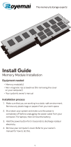
1 drive release latch 2 CD/DVD drive 3 power supply and fan
4 hard drive 5 heat sink assembly 6 power button
7 front panel door
System Board Components

Technical Overview: Dell Dimension 9200C Service Manual
file:///T|/htdocs/systems/dim9200C/en/SM_EN/techov.htm[10/31/2012 8:07:20 AM]
1 processor fan connector (CPUFAN) 16 modem connector (RJ11)
2 processor connector (CPU) 17 RJ11 internal connector
(RJ11INT)
3 processor power connector
(POWER12V)
18 video connector (VGA)
4 memory module connectors (2, 4) 19 Media Card Reader connector
(USBINT)
5 memory module connectors (1, 3) 20 USB connectors (4)
(USB_BACK)
6 battery socket (BATTERY) 21 network connector (NIC) and
USB connectors (2)
(NIC_USB1)
7 internal speaker (SPKR) 22 back panel IEEE 1394
connector (BACK1394)
8 hard drive fan connector (HDDFAN) 23 IEEE 1394 connector
(INT1394)
9 hard drive connector (SATA0) 24 PCI Express x1 connector
(SLOT2)

Technical Overview: Dell Dimension 9200C Service Manual
file:///T|/htdocs/systems/dim9200C/en/SM_EN/techov.htm[10/31/2012 8:07:20 AM]
10 CD/DVD connector (SATA1) 25 PCI Express x16 connector
(SLOT1)
11 front panel connector (FRONT PANEL) 26 standby LED (STBYLED)
12 modem 27 password jumper (CLRPSWD)
13 power connector (POWER) 28 RTC reset jumper (CLRCMOS)
14 line-in, line-out, microphone, and
center/LFE connectors (AUDIOBACK1)
29 temperature connector (THRM)
15 S/PDIF audio connector (SPDIF) 30 floppy drive connector
(FLOPPY)
Jumper Settings
Jumper locations are shown below.
Jumper Setting Description
CLRPSWD Password features are enabled (default setting).
Password features are disabled.
CLRCMOS The real-time clock has not been reset.
The real-time clock is being reset (jumpered temporarily).
jumpered unjumpered
-
Power Supply DC Connector Pin Assignments

Technical Overview: Dell Dimension 9200C Service Manual
file:///T|/htdocs/systems/dim9200C/en/SM_EN/techov.htm[10/31/2012 8:07:20 AM]
DC Power Connector P1
Pin Number Signal Name 18-AWG Wire
1 +3.3 VDC Orange
2 +3.3 VDC Orange
3 COM Black
4 +5 VDC Red
5 COM Black
6 +5 VDC Red
7 COM Black
8 POK* Gray
9 +5 VFP Purple
10 +12 VDC Yellow
11
+12 VDC
*
Yellow
12 +3.3 VDC Orange
13 +3.3 VDC/SE Orange
14 -12 VDC Blue
15 COM Black

Technical Overview: Dell Dimension 9200C Service Manual
file:///T|/htdocs/systems/dim9200C/en/SM_EN/techov.htm[10/31/2012 8:07:20 AM]
16 PS_ON* Green
17 COM Black
18 COM Black
19 COM Black
20 N.C. N.C.
21 +5 VDC Red
22 +5 VDC Red
23 +5 VDC Red
24 COM Black
*Uses 22 AWG wire instead of 18 AWG.
DC Power Connector P2
Pin Number Signal Name 18-AWG Wire
1 COM Black
2 COM Black
3 +12 VDC Yellow
4 +12 VDC Yellow
DC Power Connector P3
Pin Number Signal Name 18-AWG Wire
1 +3.3 VDC Orange
2 COM Black
3 +5 VDC Red
4 COM Black
5 +12 VDC Yellow
DC Power Connector P5


Specifications: Dell Dimension 9200C Service Manual
file:///T|/htdocs/systems/dim9200C/en/SM_EN/specs.htm[10/31/2012 8:07:23 AM]
Back to Contents Page
Specifications
Dell™ Dimension™ 9200C Service Manual
Processor
Processor types Intel® Pentium® 4, Pentium® D,
Celeron® D, Intel Core™ processor
Level 2 (L2) cache 1 MB for Pentium 4 5XX processors (with
Hyper Threading)
2 MB for Pentium 4 6XX processors (with
Hyper Threading)
2 x 2 MB for Pentium D 9XX processors
(with dual core)
2 x 1 MB for Pentium D 8XX processors
(with dual core)
256K for Celeron D 3XX processors
2 MB for Intel Core E6400 processors and
earlier
4 MB for Intel Core E6600 processors and
later
Memory
Type 533-, 667-, and 800-MHz DDR2
Memory connectors four
Memory capacities 256 MB, 512 MB, 1 GB, or 2 GB
Maximum memory 4 GB
NOTE: See Addressing Memory With 4-
GB Configurations to verify the amount of
memory available to the operating
system.
BIOS address F0000h
Computer Information
Chipset Intel G965 Express
DMA channels eight
Interrupt levels 24
BIOS chip (NVRAM) 4 Mb
NIC Integrated network interface capable of
10/100-Mbps communication
System clock 533-, 800- or 1066-MHz data rate
(depending on your processor)

Specifications: Dell Dimension 9200C Service Manual
file:///T|/htdocs/systems/dim9200C/en/SM_EN/specs.htm[10/31/2012 8:07:23 AM]
Video
Type integrated Intel Graphics Media
Accelerator X3000 or PCI Express x16
graphics expansion slot
Audio
Type Internal 7.1 channel Intel High Definition
Audio (Sigmatel STAC9227)
Expansion Bus
Bus type PCI Express x1 and x16
Bus speed PCI Express:
x1 slot bidirectional speed: 500
MB/sec
x16 slot bidirectional speed: 8
GB/sec
PCI Express:
connector one x1
connector size 36 pins
connector data width (maximum) one PCI Express lane
PCI Express:
connector one x16
connector size 164 pins
connector data width (maximum) 16 PCI Express lanes
Drives
Externally accessible one slimline 3.5-inch media bay
one slimline 5.25-inch drive bay
Available devices Serial ATA drive, USB memory devices,
floppy drive, CD drive, DVD drive,
DVD+RW drive, DVD/CD-RW combo
drive, DVD+/-RW drive, and Media Card
Reader
Internally accessible one bay for 1-inch high hard drive
Connectors
External connectors:
IEEE 1394 one 6-pin powered back panel connector
one 6-pin powered front panel connector
Video 15-hole D-SUB connector
USB 10-pin header for optional Media Card
Reader (3.5 inch bay device) and two
front panel and six back panel USB 2.0–
compliant connectors

Specifications: Dell Dimension 9200C Service Manual
file:///T|/htdocs/systems/dim9200C/en/SM_EN/specs.htm[10/31/2012 8:07:23 AM]
NOTE: The 10-pin header connector used
for the optional Media Card Reader is
populated with only nine pins for keying
purposes.
Audio six back panel connectors for line-in, line-
out/headphone, rear surround sound,
microphone, side surround sound, and
center/Low Frequency Effects (LFE)
channel
back panel S/PDIF connector
front panel miniature headphone
connector for line-out
front panel microphone connector
Network adapter RJ45 connector
Modem RJ11 (MDC 1.5) connector and internally
accessible 3-pin header that connects the
modem to RJ11
Temperature Sensor one 2-pin connector
System board connectors:
Serial ATA two 7-pin connectors
Fan two 5-pin connectors (one for the CPU fan
and one for the optional hard drive fan
connector.)
PCI Express x1 36-pin connector
PCI Express x16 164-pin connector
USB 10-pin header for optional Media Card
Reader (3.5-inch bay device)
MDC one 12-pin connector
Floppy connector one 26-pin connector
Front panel one 40-pin header
Power one 2 x 12 connector
Processor power one 2 x 2 connector
IEEE 1394 one 2 x 5 header — always connected by
cable to the front panel; supports front
panel IEEE 1394 port
Controls and Lights
Power control push button
Power light green light — Blinking green in sleep
state; solid green for power-on state.
amber light — Blinking amber indicates a
problem with an installed device; solid
amber indicates an internal power
problem (see "Power Problems" in your
computer Owner's Manual).
Hard drive access light green
Link integrity light (on integrated network
adapter)
green light — A good connection exists
between a 10-Mbps network and the
computer.

Specifications: Dell Dimension 9200C Service Manual
file:///T|/htdocs/systems/dim9200C/en/SM_EN/specs.htm[10/31/2012 8:07:23 AM]
orange light — A good connection exists
between a 100-Mbps network and the
computer.
off (no light) — The computer is not
detecting a physical connection to the
network.
Activity light (on integrated network
adapter)
yellow blinking light
Diagnostic lights four lights on the front panel (see
Diagnostic Lights
for an explanation of the
diagnostic light codes)
Standby power light STBYLED on the system board
Activity light (optional Media Card Reader) green blinking light
Power
DC power supply:
Wattage 275 W
Heat dissipation 935 BTU/hr
Voltage (see the safety instructions
in the Product Information Guide
for important voltage setting
information)
manual selection power supplies — 90 to
135 V at 50/60 Hz; 180 to 265 V at 50/60
Hz
Backup battery 3-V CR2032 lithium coin cell
Physical
Height 31.8 cm (12.5 inches)
Width 9.4 cm (3.7 inches)
Depth 36.8 cm (14.5 inches)
Weight 6.89 kg (15.2 lb)
Environmental
Temperature:
Operating 10° to 35°C (50° to 95°F)
Storage –40° to 65°C (–40° to 149°F)
Relative humidity 20% to 80% (noncondensing)
Maximum vibration:
Operating 0.25 G at 3 to 200 Hz at 0.5 octave/min
Storage 0.5 G at 3 to 200 Hz at 1 octave/min
Maximum shock:
Operating bottom half-sine pulse with a change in
velocity of 50.8 cm/sec (20 in/sec)
Storage 27-G faired square wave with a velocity
change of 508 cm/sec (200 in/sec)
Altitude:
Operating –15.2 to 3048 m (–50 to 10,000 ft)


Troubleshooting: Dell Dimension 9200C Service Manual
file:///T|/htdocs/systems/dim9200C/en/SM_EN/tshoot.htm[10/31/2012 8:07:27 AM]
Back to Contents Page
Troubleshooting
Dell™ Dimension™ 9200C Service Manual
Dell Diagnostics
System Lights
Diagnostic Lights
Beep Codes
Dell Diagnostics
CAUTION: Before you begin any of the procedures in this section, follow the safety instructions located in
the Product Information Guide.
When to Use the Dell Diagnostics
If you experience a problem with your computer, perform the checks in this section and run the Dell Diagnostics before you
contact Dell for technical assistance.
NOTE: The Dell Diagnostics only operate on Dell computers.
Starting the Dell Diagnostics
1. Turn on (or restart) your computer.
2. When the DELL logo appears, press <F12> immediately.
NOTE: Keyboard failure may result when a key is held down for extended periods of time. To avoid possible
keyboard failure, press and release <F12> in even intervals to open the Boot Device Menu.
If you wait too long and the operating system logo appears, continue to wait until you see the Microsoft® Windows®
desktop, then shut down your computer and try again.
3. At the Boot Device Menu, use the up- and down-arrow keys or press the appropriate number on the keyboard to
highlight Boot to Utility Partition, and then press <Enter>.
NOTE: The Quickboot feature changes the boot sequence for the current boot only. Upon restart, the computer
boots according to the boot sequence specified in system setup.
4. At the Dell Diagnostics Main Menu, left-click with the mouse, or press <Tab> and then <Enter>, to select the test you
want to run (see Dell Diagnostics Main Menu
).
NOTE: Write down any error codes and problem descriptions exactly as they appear and follow the instructions
on the screen.
5. After all tests have completed, close the test window to return to the Dell Diagnostics Main Menu.
6. Close the Main Menu window to exit the Dell Diagnostics and restart the computer.
/