Dell Dimension 5000 User manual

Category
Networking
Type
User manual

This manual is also suitable for

Dell™Dimension™5000ServiceManual
Before You Begin
Removing the Computer Cover
AboutYourDell™Dimension™5000Computer
Advanced Troubleshooting
Removing and Installing Parts
Replacing the Computer Cover
Specifications
Technical Overview
System Setup
Notes, Notices, and Cautions
Abbreviations and Acronyms
For a complete list of abbreviations and acronyms, see the Dell Dimension Help file.
IfyoupurchasedaDell™nSeriescomputer,anyreferencesinthisdocumenttoMicrosoft®
Windows®operating systems are not applicable.
Information in this document is subject to change without notice.
©2004DellInc.Allrightsreserved.
Reproduction in any manner whatsoever without the written permission of Dell Inc. is strictly forbidden.
Trademarks used in this text: Dell, the DELL logo, Inspiron, Dell Precision, Dimension, OptiPlex, Latitude, PowerEdge, PowerVault, PowerApp, and Dell OpenManage are trademarks of Dell
Inc.; Intel and Pentium are registered trademarks of Intel Corporation; Microsoft and Windows are registered trademarks of Microsoft Corporation.
Other trademarks and trade names may be used in this document to refer to either the entities claiming the marks and names or their products. Dell Inc. disclaims any
proprietary interest in trademarks and trade names other than its own.
Model DCSM
November2004Rev.A00
NOTE: A NOTE indicates important information that helps you make better use of your computer.
NOTICE: A NOTICE indicates either potential damage to hardware or loss of data and tells you how to avoid the problem.
CAUTION: A CAUTION indicates a potential for property damage, personal injury, or death.
Back to Contents Page
AboutYourDell™Dimension™5000Computer
Dell™Dimension™5000ServiceManual
Front View of Computer
Back View of Computer
Front View of Computer
1
cover latch
release
Use this latch release to remove the cover.
2
CD or DVD
activity light
The drive light is on when the computer reads data from the CD or DVD drive.
3
CD or DVD eject
button
Press to eject a disk from the CD or DVD drive.
4
FlexBay drive
Can contain an optional floppy drive or optional Media Card Reader.
5
USB 2.0
connectors (2)
Use the front USB connectors for devices that you connect occasionally, such as joysticks or cameras. It is recommended that you use
the back USB connectors for devices that typically remain connected, such as printers and keyboards.
6
hard-drive
activity light
The hard drive activity light is on when the computer reads data from or writes data to the hard drive. The light might also be on
when a device such as a CD player is operating.
7
vents
For adequate cooling, do not block any of the vents.
NOTICE: Ensure that there is a minimum of two inches of space between all vents and any object near these vents.
NOTICE: Keep the vent area clean and dust-free to ensure that the system is adequately ventilated. Use only a dry cloth to clean
the vent area to avoid water damage to the system.
8
power button
Press to turn on the computer.
NOTICE: To avoid losing data, do not use the power button to turn off the computer. Instead, perform an operating system
shutdown.
9
headphone
connector
Use the headphone connector to attach headphones and most kinds of speakers.
Back View of Computer
10
microphone
connector
Use the microphone connector to attach a personal computer microphone for voice or musical input into a sound or telephony
program.
11
diagnostic lights
(4)
Use the lights to help you troubleshoot a computer problem based on the diagnostic code. For more information, see "Diagnostic
Lights."
12
Service Tag
Used to identify your computer when you access the Dell Support website or call technical support.
1
Insert the power cable.
2
l Line-in connector Use the blue line-in connector to attach a
record/playback device such as a cassette player, CD player, or VCR.
l Line-out connector Use the green line-out connector to attach
headphones and most speakers with integrated amplifiers.
l Microphone connector Use the pink microphone connector to
attach a personal computer microphone for voice or musical input
into a sound or telephony program.
l Surround connector Use the black surround connector to attach
multichannel-capable speakers.
l Center/subwoofer connector Use the yellow subwoofer connector
to attach multiple speakers.
3
Use the back USB connectors for devices that typically remain connected,
such as printers, keyboards, or for bootable USB devices.
It is recommended that you use the front USB connectors for devices that
you connect occasionally, such as joysticks or cameras.
4
To attach your computer to a network or broadband device, connect one
end of a network cable to either a network jack or your network or
broadband device. Connect the other end of the network cable to the
network adapter connector on your computer. A click indicates that the
network cable has been securely attached.
NOTE: Do not plug a telephone cable into the network connector.
On computers with a network connector card, use the connector on the
card.
It is recommended that you use Category 5 wiring and connectors for your
network. If you must use Category 3 wiring, force the network speed to 10
Mbps to ensure reliable operation.
5
If your monitor has a VGA connector, plug it into the VGA connector on the
computer.
6
Connect a serial device, such as a handheld device, to the serial port. The
default designations are COM1 for serial connector 1 and COM2 for serial
connector 2.
For more information, see "System Setup" options.
7
Connect a parallel device, such as a printer, to the parallel connector. If
Back to Contents Page
you have a USB printer, plug it into a USB connector.The integrated parallel
connector is automatically disabled if the computer detects an installed
card containing a parallel connector configured to the same address. For
more information, see "System Setup" options.
8
Access connectors for any installed PCI cards (two slots) and PCI Express
cards (one x16 slot and one x1 slot).
Back to Contents Page
Advanced Troubleshooting
Dell™Dimension™5000ServiceManual
Dell Diagnostics
System Lights
Diagnostic Lights
Beep Codes
Dell Diagnostics
When to Use the Dell Diagnostics
If you experience a problem with your computer, perform the checks in this section and run the Dell Diagnostics before you contact Dell for technical
assistance.
It is recommended that you print these procedures before you begin.
Enter "system setup" to review your computer's configuration information, and ensure that the device you want to test displays in system setup and is active.
Start the Dell Diagnostics from either your hard drive or from the Drivers and Utilities CD (also known as the ResourceCD - optional).
Starting the Dell Diagnostics From Your Hard Drive
1. Turn on (or restart) your computer.
2. WhentheDELL™logoappears,press<F12>immediately.
If you wait too long and the operating system logo appears, continue to wait until you see the Microsoft®Windows®desktop. Then shut down your
computer and try again.
3. When the boot device list appears, highlight Boot to Utility Partition and press <Enter>.
4. When the Dell Diagnostics Main Menu appears, select the test you want to run.
Starting the Dell Diagnostics From the Drivers and Utilities CD (optional)
1. Insert the Drivers and Utilities CD (optional).
2. Shut down and restart the computer.
When the DELL logo appears, press <F12> immediately.
If you wait too long and the Windows logo appears, continue to wait until you see the Windows desktop. Then shut down your computer and try again.
3. When the boot device list appears, highlight IDE CD-ROM Device and press <Enter>.
4. Select the IDE CD-ROM Device option from the CD boot menu.
5. Select the Boot from CD-ROM option from the menu that appears.
CAUTION: Before you begin any of the procedures in this section, follow the safety instructions located in the Product Information Guide.
NOTE: The Drivers and Utilities CD (ResourceCD) is optional, and as such, may not ship with all computers.
NOTICE: TheDellDiagnosticsworksonlyonDell™computers.
NOTE: If you see a message stating that no diagnostics utility partition has been found, run the Dell Diagnostics from your Drivers and Utilities CD
(optional).
NOTE: The next steps change the boot sequence for one time only. On the next start-up, the computer boots according to the devices specified in
system setup.
6. Type 1 to start the ResourceCD menu.
7. Type 2 to start the Dell Diagnostics.
8. Select Run the 32 Bit Dell Diagnostics from the numbered list. If multiple versions are listed, select the version appropriate for your computer.
9. When the Dell Diagnostics Main Menu appears, select the test you want to run.
Dell Diagnostics Main Menu
1. After the Dell Diagnostics loads and the Main Menu screen appears, click the button for the option you want.
2. If a problem is encountered during a test, a message appears with an error code and a description of the problem. Write down the error code and
problem description and follow the instructions on the screen.
If you cannot resolve the error condition, contact Dell.
3. If you run a test from the Custom Test or Symptom Tree option, click the applicable tab described in the following table for more information.
4. When the tests are completed, if you are running the Dell Diagnostics from the Drivers and Utilities CD, remove the CD.
5. Close the test screen to return to the Main Menu screen. To exit the Dell Diagnostics and restart the computer, close the Main Menu screen.
System Lights
Your power button light and hard-drive light may indicate a computer problem.
Option
Function
Express Test
Performs a quick test of devices. This test typically takes 10 to 20 minutes and requires no interaction on your part. Run Express Test first to
increase the possibility of tracing the problem quickly.
Extended
Test
Performs a thorough check of devices. This test typically takes 1 hour or more and requires you to answer questions periodically.
Custom Test
Tests a specific device. You can customize the tests you want to run.
Symptom
Tree
Lists the most common symptoms encountered and allows you to select a test based on the symptom of the problem you are having.
NOTE: The Service Tag for your computer is located at the top of each test screen. If you contact Dell, technical support will ask for your Service Tag.
Your computer's Service Tag is listed in the system information option in system setup.
Function
Displays the results of the test and any error conditions encountered.
Displays error conditions encountered, error codes, and the problem description.
Describes the test and may indicate requirements for running the test.
Displays your hardware configuration for the selected device.
The Dell Diagnostics obtains configuration information for all devices from system setup, memory, and various internal tests, and it displays
the information in the device list in the left pane of the screen. The device list may not display the names of all the components installed on
your computer or all devices attached to your computer.
Allows you to customize the test by changing the test settings.
Power Light
Problem Description
Suggested Resolution
Solid green
Power is on, and the computer is operating normally. On
the desktop computer, a solid green light indicates a
network connection.
No corrective action is required.
Blinking green
The computer is in the suspended state (Microsoft®
Windows®2000 and Windows XP).
Press the power button, move the mouse, or press a key
on the keyboard to wake the computer.
Blinks green several times and then
turns off
A configuration error exists.
Check the diagnostic lights to see if the specific problem is
identified.
Solid yellow
The Dell Diagnostics is running a test, or a device on the
system board may be faulty or incorrectly installed.
If the Dell Diagnostics is running, allow the testing to
complete.
Check the diagnostic lights to see if the specific problem is
Diagnostic Lights
To help you troubleshoot a problem, your small form factor, small desktop, and small mini-tower computers have four lights labeled "A," "B," "C," and "D" on
the back panel. The lights can be yellow or green. When the computer starts normally, the patterns or codes on the lights change as the boot process
completes. If the POST portion of system boot completes successfully, all four lights display solid green. If the computer malfunctions during the POST process,
the pattern displayed on the lights may help identify where in the process the computer halted.
identified.
If the computer does not boot, contact Dell for technical
assistance.
Blinking yellow
A power supply or system board failure has occurred.
Check the diagnostic lights to see if the specific problem is
identified. Also, see "Power Problems."
Solid green and a beep code during
POST
A problem was detected while the BIOS was executing.
See "Beep Codes" for instructions on diagnosing the beep
code. Also, check the diagnostic lights to see if the specific
problem is identified.
Solid green power light and no beep
code and no video during POST
The monitor or the graphics card may be faulty or
incorrectly installed.
Check the diagnostic lights to see if the specific problem is
identified. See "Video and Monitor Problems."
Solid green power light and no beep
code but the computer locks up
during POST
An integrated system board device may be faulty.
Check the diagnostic lights to see if the specific problem is
identified. If the problem is not identified, contact Dell for
technical assistance.
CAUTION: Before you begin any of the procedures in this section, follow the safety instructions located in the Product Information Guide.
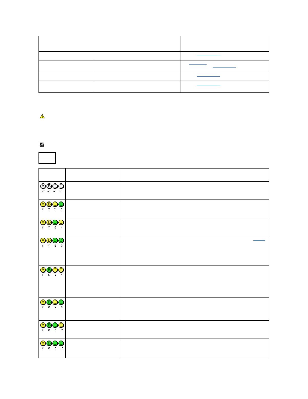
NOTE: The orientation of the diagnostic lights may vary depending on the system type. The diagnostic lights can appear either vertical or horizontal.
Y = Yellow
G = Green
Light Pattern
Problem Description
Suggested Resolution
The computer is in a normal off
condition or a possible pre-BIOS
failure has occurred.
Plug the computer into a working electrical outlet and press the power button.
A possible BIOS failure has
occurred; the computer is in the
recovery mode.
Run the BIOS Recovery utility, wait for recovery completion, and then restart the computer.
A possible processor failure has
occurred.
Reinstall the processor and restart the computer.
Memory modules are detected, but
a memory failure has occurred.
l If you have one memory module installed, reinstall it and restart the computer. See "Memory"
for instructions on how to remove and install memory modules.
l If you have two or more memory modules installed, remove the modules, reinstall one module,
and then restart the computer. If the computer starts normally, reinstall an additional module.
Continue until you have identified a faulty module or reinstalled all modules without error.
l If available, install properly working memory modules of the same type into your computer.
l If the problem persists, contact Dell.
A possible expansion card failure
has occurred.
l Determine if a conflict exists by removing a card (not the graphics card) and then restarting
the computer.
l If the problem persists, reinstall the card that you removed, remove a different card, and then
restart the computer.
l Repeat this process for each card. If the computer starts normally, troubleshoot the last card
removed from the computer for resource conflicts.
l Move each card one at a time to a different PCI slot and restart the computer after each move.
l If the problem persists, contact Dell.
A possible graphics card failure has
occurred.
l If the computer has a graphics card, remove the card, reinstall it, and then restart the
computer.
l If the problem still exists, install a graphics card that you know works and restart the
computer.
l If the problem persists or the computer has integrated graphics, contact Dell.
A possible floppy or hard drive
failure has occurred.
Reseat all power and data cables and restart the computer.
A possible USB failure has
occurred.
Reinstall all USB devices, check cable connections, and then restart the computer.
Beep Codes
Your computer might emit a series of beeps during start-up if the monitor cannot display errors or problems. This series of beeps, called a beep code, identifies
a problem. One possible beep code (code 1-3-1) consists of one beep, a burst of three beeps, and then one beep. This beep code tells you that the computer
encountered a memory problem.
If your computer beeps during start-up:
1. Write down the beep codes.
2. Run the Dell Diagnostics to identify a more serious cause.
3. Contact Dell for technical assistance.
No memory modules are detected.
l If you have one memory module installed, reinstall it and restart the computer. See "Memory"
for instructions on how to remove and install memory modules.
l If you have two or more memory modules installed, remove the modules, reinstall one module,
and then restart the computer. If the computer starts normally, reinstall an additional module.
Continue until you have identified a faulty module or reinstalled all modules without error.
l If available, install properly working memory of the same type into your computer.
l If the problem persists, contact Dell.
Memory modules are detected, but
a memory configuration or
compatibility error exists.
l Ensure that no special memory module/memory connector placement requirements exist.
l Verify that the memory modules that you are installing are compatible with your computer (see
"Memory").
l If the problem persists, contact Dell.
Other failure has occurred.
l Ensure that the cables are properly connected to the system board from the hard drive, CD
drive, and DVD drive.
l Check the computer message that appears on your monitor screen.
l If the problem persists, contact Dell.
The computer is in a normal
operating condition after POST.
None.
Code
Cause
1-1-2
Microprocessor register failure
1-1-3
NVRAM read/write failure
1-1-4
ROM BIOS checksum failure
1-2-1
Programmable interval timer failure
1-2-2
DMA initialization failure
1-2-3
DMA page register read/write failure
1-3
Video Memory Test failure
1-3-1 through 2-4-4
Memory not being properly identified or used
3-1-1
Slave DMA register failure
3-1-2
Master DMA register failure
3-1-3
Master interrupt mask register failure
3-1-4
Slave interrupt mask register failure
3-2-2
Interrupt vector loading failure
3-2-4
Keyboard Controller Test failure
3-3-1
NVRAM power loss
3-3-2
Invalid NVRAM configuration
3-3-4
Video Memory Test failure
3-4-1
Screen initialization failure
3-4-2
Screen retrace failure
3-4-3
Search for video ROM failure
4-2-1
No timer tick
4-2-2
Shutdown failure
4-2-3
Gate A20 failure
4-2-4
Unexpected interrupt in protected mode
4-3-1
Memory failure above address 0FFFFh
4-3-3
Timer-chip counter 2 failure
4-3-4
Time-of-day clock stopped
4-4-1
Serial or parallel port test failure
Back to Contents Page
4-4-2
Failure to decompress code to shadowed memory
4-4-3
Math-coprocessor test failure
4-4-4
Cache test failure
Back to Contents Page
Before You Begin
Dell™Dimension™5000ServiceManual
Getting Started
Recommended Tools
Turning Off Your Computer
Before Working Inside Your Computer
Getting Started
This section provides procedures for removing and installing the components in your computer. Unless otherwise noted, each procedure assumes that the
following conditions exist:
l You have performed the steps in "Turning Off Your Computer" and "Before Working Inside Your Computer."
l YouhavereadthesafetyinformationinyourDell™Product Information Guide.
l A component can be replaced by performing the removal procedure in reverse order.
Recommended Tools
The procedures in this document may require the following tools:
l Small flat-blade screwdriver
l Phillips screwdriver
l Flash BIOS update program floppy disk or CD
Turning Off Your Computer
1. Shut down the operating system:
a. Save and close any open files, exit any open programs, click the Start button, and then click Turn Off Computer.
b. In the Turn off computer window, click Turn off.
The computer turns off after the operating system shutdown process finishes.
2. Ensure that the computer and any attached devices are turned off. If your computer and attached devices did not automatically turn off when you shut
down your operating system, press and hold the power button for 4 seconds.
Before Working Inside Your Computer
Use the following safety guidelines to help protect your computer from potential damage and to help ensure your own personal safety.
1. Turn off your computer.
NOTICE: To avoid losing data, save and close any open files and exit any open programs before you turn off your computer.
CAUTION: Before you begin any of the procedures in this section, follow the safety instructions in the Product Information Guide.
CAUTION: Handle components and cards with care. Do not touch the components or contacts on a card. Hold a card by its edges or by its metal
mounting bracket. Hold a component such as a processor by its edges, not by its pins.
NOTICE: Only a certified service technician should perform repairs on your computer. Damage due to servicing that is not authorized by Dell is not
covered by your warranty.
NOTICE: When you disconnect a cable, pull on its connector or on its strain-relief loop, not on the cable itself. Some cables have a connector with
locking tabs; if you are disconnecting this type of cable, press in on the locking tabs before you disconnect the cable. As you pull connectors apart, keep
them evenly aligned to avoid bending any connector pins. Also, before you connect a cable, ensure that both connectors are correctly oriented and
aligned.
NOTICE: To avoid damaging the computer, perform the following steps before you begin working inside the computer.
NOTICE: To disconnect a network cable, first unplug the cable from your computer and then unplug it from the network wall jack.
2. Disconnect any telephone or telecommunication lines from the computer.
3. Disconnect your computer and all attached devices from their electrical outlets, and then press the power button to ground the system board.
4. Open the computer cover.
Back to Contents Page
CAUTION: To guard against electrical shock, always unplug your computer from the electrical outlet before opening the cover.
NOTICE: Before touching anything inside your computer, ground yourself by touching an unpainted metal surface, such as the metal at the back of the
computer. While you work, periodically touch an unpainted metal surface to dissipate any static electricity that could harm internal components.
Back to Contents Page
Replacing the Computer Cover
Dell™Dimension™5000ServiceManual
1. Ensure that all cables are connected, and fold cables out of the way.
Gently pull the power cables toward you so that they do not get caught underneath the drives.
2. Ensure that no tools or extra parts are left inside the computer.
3. Align the bottom of the cover with the tabs located along the bottom edge of the computer.
4. Using the tabs as leverage, rotate the cover downward and close.
5. Snap the cover into place by pulling back on the cover latch release, and then releasing the latch release when the cover is seated.
6. Ensure that the cover is seated correctly before moving it to the upright position.
7. Connect your computer and devices to electrical outlets, and turn them on.
Back to Contents Page
CAUTION: Before you begin any of the procedures in this section, follow the safety instructions located in the Product Information Guide.
NOTICE: To connect a network cable, first plug the cable into the network device and then plug it into the computer.
Back to Contents Page
Removing the Computer Cover
Dell™Dimension™5000ServiceManual
1. Follow the procedures in "Before you Begin."
2. Lay your computer on its side with the computer cover facing up.
3. Pull back the cover latch release on the top panel.
4. Locate the three hinge tabs on the bottom edge of the computer.
5. Grip the sides of the computer cover and pivot the cover up, using the bottom hinges as leverage points.
6. Release the cover from the hinge tabs and set it aside in a secure location.
Back to Contents Page
CAUTION: Before you begin any of the procedures in this section, follow the safety instructions located in the Product Information Guide.
CAUTION: To guard against electrical shock, always unplug your computer from the electrical outlet before removing the cover.
NOTICE: Ensure that sufficient space exists to support the removed coverat least 30 cm (1 ft) of desk top space.
NOTICE: Ensure that you are working on a level, protected surface to avoid scratching either the computer or the surface on which it is resting.
Back to Contents Page
Removing and Installing Parts
Memory
You can increase your computer memory by installing memory modules on the system board.
YourcomputersupportsDDR2memory.
DDR2 Memory Overview
DDR2 memory modules should be installed in pairs of matched memory size, speed, and technology. If the DDR2 memory modules are not installed in matched
pairs, the computer will continue to operate, but with a slight reduction in performance. See the label on the module to determine the module's capacity.
The recommended memory configurations are:
¡ A pair of matched memory modules installed in DIMM connectors 1 and 2
or
¡ A pair of matched memory modules installed in DIMM connectors 1 and 2 and another matched pair installed in DIMM connectors 3 and 4
l If you install mixed pairs of DDR2 400-MHz (PC2-3200) and DDR2 533-MHz (PC2-4300) memory, the modules function at the slowest speed installed.
l Be sure to install a single memory module in DIMM connector 1, the connector closest to the processor, before you install modules in the other
connectors.
Dell™Dimension™5000ServiceManual
Memory
Cards
Drive Panels
Drives
Hard Drive
Floppy Drive
Media Card Reader
CD/DVD Drive
Processor
System Board
Power Supply
Battery
NOTE: Always install DDR2 memory modules in the order indicated on the system board.
NOTICE: Do not install ECC memory modules.
NOTE: Memory purchased from Dell is covered under your computer warranty.
NOTICE: If you remove your original memory modules from the computer during a memory upgrade, keep them separate from any new modules that
you may have, even if you purchased the new modules from Dell. If possible, do not pair an original memory module with a new memory module.
Otherwise, your computer may not start properly. You should install your original memory modules in pairs either in DIMM connectors 1 and 2 or DIMM
connectors 3 and 4.
Addressing Memory With 4-GB Configurations
Your computer supports a maximum of 4 GB of memory when you use four 1-GB DIMMs. Current operating systems, such as Microsoft®Windows®XP, can
only use a maximum of 4 GB of address space; however, the amount of memory available to the operating system is less than 4 GB. Certain components
within the computer require address space in the 4-GB range. Any address space reserved for these components cannot be used by computer memory.
Installing Memory
1. Follow the procedures in "Before you Begin."
2. Lay the computer on its side so that the system board is on the bottom of the inside of the computer.
3. Press out the securing clip at each end of the memory module connector.
4. Align the notch on the bottom of the module with the crossbar in the connector.
5. Insert the module into the connector until the module snaps into position.
If you insert the module correctly, the securing clips snap into the cutouts at each end of the module.
CAUTION: Before you begin any of the procedures in this section, follow the safety instructions located in the Product Information Guide.
NOTICE: To prevent static damage to components inside your computer, discharge static electricity from your body before you touch any of your
computer's electronic components. You can do so by touching an unpainted metal surface on the computer chassis.
1
memory connector closest to processor
2
securing clips (2)
3
connector
1
cutouts (2)
2
memory module
3
notch
4
crossbar
NOTICE: To avoid damage to the memory module, press the module straight down into the connector while you apply equal force to each end of the
module.
6. Replace the computer cover.
7. Connect your computer and devices to electrical outlets, and turn them on.
8. Right-click the My Computer icon and click Properties.
9. Click the General tab.
10. To verify that the memory is installed correctly, check the amount of memory (RAM) listed.
Removing Memory
1. Follow the procedures in "Before you Begin."
2. Press out the securing clip at each end of the memory module connector.
3. Grasp the module and pull up.
If the module is difficult to remove, gently ease the module back and forth to remove it from the connector.
Cards
YourDell™computerprovidesthefollowingslotsforPCIandPCIExpresscards:
l Two PCI card slots
l One PCI Express x16 card slot
l One PCI Express x1 card slot
PCI Cards
Your computer supports two PCI cards.
If you are installing or replacing a card, follow the procedures in the next section. If you are removing but not replacing a PCI card, see "Removing a PCI Card."
If you are replacing a card, remove the current driver for the card from the operating system.
NOTICE: To connect a network cable, first plug the cable into the network device and then plug the cable into the computer.
CAUTION: Before you begin any of the procedures in this section, follow the safety instructions located in the Product Information Guide.
NOTICE: To prevent static damage to components inside your computer, discharge static electricity from your body before you touch any of your
computer's electronic components. You can do so by touching an unpainted metal surface on the computer chassis.
If you are installing or replacing a PCI Express card, see "Installing a PCI Express Card."
Installing a PCI Card
1. Follow the procedures in "Before you Begin."
2. Gently push the release tab on the card retention door from the inside to pivot the door open. Because the door is captive, it will remain in the open
position.
3. If you are installing a new card, remove the filler bracket to create a card-slot opening. Then continue with step5.
4. If you are replacing a card that is already installed in the computer, remove the card.
If necessary, disconnect any cables connected to the card. Grasp the card by its top corners, and ease it out of its connector.
5. Prepare the card for installation.
See the documentation that came with the card for information on configuring the card, making internal connections, or otherwise customizing it for your
computer.
6. Place the card in the connector and press down firmly. Ensure that the card is fully seated in the slot.
1
filler bracket
2
alignment guide
3
alignment bar
4
card retention door
5
release tab
CAUTION: Some network adapters automatically start the computer when they are connected to a network. To guard against electrical shock, be
sure to unplug your computer from its electrical outlet before installing any cards.
1
alignment bar
7. Before you close the card retention door, ensure that:
l The tops of all cards and filler brackets are flush with the alignment bar.
l The notch in the top of the card or filler bracket fits around the alignment guide.
8. Close the card retention door by snapping it into place to secure the card(s).
9. Connect any cables that should be attached to the card.
See the documentation for the card for information about the card's cable connections.
10. Replace the computer cover, reconnect the computer and devices to electrical outlets, and then turn them on.
11. If you installed a sound card:
a. Enter system setup, select Audio Controller, and then change the setting to Off.
b. Connect external audio devices to the sound card's connectors. Do not connect external audio devices to the microphone, speaker/headphone,
or line-in connectors on the back panel.
12. If you installed an add-in network adapter and want to disable the integrated network adapter:
a. Enter system setup, select Network Controller, and then change the setting to Off.
b. Connect the network cable to the add-in network adapter's connectors. Do not connect the network cable to the integrated connector on the
back panel.
13. Install any drivers required for the card as described in the card documentation.
Removing a PCI Card
1. Follow the procedures in "Before you Begin."
2. If you are removing the card permanently, install a filler bracket in the empty card-slot opening.
If you need a filler bracket, contact Dell.
2
alignment guide
3
fully seated card
4
not fully seated card
5
bracket within slot
6
bracket caught outside of slot
1
card retention door
2
release tab
NOTICE: Do not route card cables over or behind the cards. Cables routed over the cards can prevent the computer cover from closing properly or
cause damage to the equipment.
NOTICE: To connect a network cable, first plug the cable into the network device and then plug the cable into the computer.
NOTE: Installing filler brackets over empty card-slot openings is necessary to maintain FCC certification of the computer. The brackets also keep dust
and dirt out of your computer.
3. Replace the computer cover, reconnect the computer and devices to electrical outlets, and then turn them on.
4. Remove the card's driver from the operating system.
5. If you removed a sound card:
a. Enter system setup, select Audio Controller, and then change the setting to On.
b. Connect external audio devices to the audio connectors on the back panel of the computer.
6. If you removed an add-in network connector:
a. Enter system setup, select Network Controller, and then change the setting to On.
b. Connect the network cable to the integrated connector on the back panel of the computer.
PCI Express Cards
Your computer supports one PCI Express x16 card and one PCI Express x1 card.
If you are installing or replacing a PCI Express card, follow the procedures in the next section. If you are removing but not replacing a card, see "Removing a
PCI Express Card."
If you are replacing a card, remove the current driver for the card from the operating system.
If you are installing or replacing a PCI card, see "Installing a PCI Card."
Installing a PCI Express Card
1. Follow the procedures in "Before you Begin."
2. Gently push the release tab on the card retention door from the inside to pivot the door open. Because the door is captive, it will remain in the open
position.
3. If your computer includes a card retention mechanism, to secure the x16 card in place from the top:
a. Pivot the mechanism upward and gently squeeze in on the sides to release the mechanism from the two tab slots holding it in place.
b. Set the retention mechanism aside in a secure location.
4. If you are installing a new card, remove the filler bracket to create a card-slot opening. Then continue with step5.
5. If you are replacing a card that is already installed in the computer, remove the card.
NOTICE: To connect a network cable, first plug the cable into the network device and then plug the cable into the computer.
1
release tabs (2)
2
card retention mechanism
3
card retention door
If necessary, disconnect any cables connected to the card. If your card includes a retention mechanism, remove the top of the retention mechanism by
pressing the tab and pulling up on the top. Gently pull the securing tab, grasp the card by its top corners, and then ease it out of its connector.
6. Prepare the card for installation.
See the documentation that came with the card for information on configuring the card, making internal connections, or otherwise customizing it for your
computer.
7. If you are installing the card into the x16 card connector, position the card so the securing slot is aligned with the securing tab, and gently pull the
securing tab.
8. Place the card in the connector and press down firmly. Ensure that the card is fully seated in the slot.
9. If you replaced a card that was already installed in the computer and you removed the retention mechanism, you may reinstall the retention mechanism.
10. Before replacing the card retention mechanism, ensure that:
l The tops of all cards and filler brackets are flush with the alignment bar.
l The notch in the top of the card or filler bracket fits around the alignment guide.
1
PCI Express x16 card slot
2
PCI Express x16 card
3
securing tab
4
PCI Express x1 card
5
PCI Express x1 card slot
CAUTION: Some network adapters automatically start the computer when they are connected to a network. To guard against electrical shock, be
sure to unplug your computer from its electrical outlet before installing any cards.
NOTICE: Ensure that you release the securing tab to unseat the card. If the card is not removed correctly, the system board may be damaged.
1
alignment bar
2
alignment guide
3
fully seated card
4
not fully seated card
5
bracket within slot
6
bracket caught outside of slot
  • Page 1 1
  • Page 2 2
  • Page 3 3
  • Page 4 4
  • Page 5 5
  • Page 6 6
  • Page 7 7
  • Page 8 8
  • Page 9 9
  • Page 10 10
  • Page 11 11
  • Page 12 12
  • Page 13 13
  • Page 14 14
  • Page 15 15
  • Page 16 16
  • Page 17 17
  • Page 18 18
  • Page 19 19
  • Page 20 20
  • Page 21 21
  • Page 22 22
  • Page 23 23
  • Page 24 24
  • Page 25 25
  • Page 26 26
  • Page 27 27
  • Page 28 28
  • Page 29 29
  • Page 30 30
  • Page 31 31
  • Page 32 32
  • Page 33 33
  • Page 34 34
  • Page 35 35
  • Page 36 36
  • Page 37 37
  • Page 38 38
  • Page 39 39
  • Page 40 40
  • Page 41 41
  • Page 42 42
  • Page 43 43
  • Page 44 44
  • Page 45 45
  • Page 46 46
  • Page 47 47
  • Page 48 48
  • Page 49 49
  • Page 50 50
  • Page 51 51
  • Page 52 52
  • Page 53 53
  • Page 54 54
  • Page 55 55

Dell Dimension 5000 User manual

Category
Networking
Type
User manual
This manual is also suitable for

Ask a question and I''ll find the answer in the document

Finding information in a document is now easier with AI