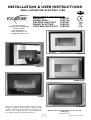
FocalPoint Kavachi Electric Wall Mounted User manual
- Type
- User manual

INSTALLATION & USER INSTRUCTIONS
All instructions must be handed to the user for
safekeeping.
MODELS COVERED BY THESE INSTRUCTIONS
KAVACHI - F500181
ANDALUSIA - F500164
VALERIA ELECTRIC F500307
PIANO ELECTRIC- F500225
CASCARA ELECTRIC - F500282
Focal Point Fires plc.
Christchurch, Dorset BH23 2BT
Tel: 01202 499330
Fax: 01202 499326
www.focalpointfires.co.uk
e : sales@focalpointfires.co.uk
WALL MOUNTED ELECTRIC FIRE
Please note : Except where otherwise stated, all rights,
including copyright in the text, images and layout of this
booklet is owned by Focal Point Fires plc. You are not per-
mitted to copy or adapt any of the content without the
prior written permission of Focal Point Fires plc.
1
Revision D - 11/10
© 2010 Focal Point Fires plc.
GB IE
KAVACHI
ANDALUSIA
PIANO
CASCARA
VALERIA

• DO NOT use this appliance immediately below a fixed socket outlet.
• DO NOT use this appliance in the immediate vicinity of a bath, shower, swimming pool or other area where water/moisture
could present a hazard.
• WARNING: This heater is not equipped with a device to control the room temperature. Do not use this heater in small rooms
when they are occupied by persons not capable of leaving the room on their own, unless constant supervision is provided.
• CAUTION: This appliance must not be used in conjunction with any timer, programmer or thermal control, or any other device
that will switch on the appliance automatically, as a fire risk may occur if the heater is accidentally covered or displaced.
• Do not allow the heater to be covered as this may cause overheating. The appliance must not be placed near curtains or simi-
lar material. A clearance space of at least one metre should be allowed in front of the appliance.
• The electrical socket that the appliance uses MUST be easily accessible. Do not route the supply cord directly in front of the heater unit.
• If the cord is damaged, it must be replaced by a service agent or competent person.
• This appliance is not intended for use by persons (including children) with reduced physical, sensory or mental capabilities, or
lack of experience and knowledge, unless they have been given supervision or instruction concerning use of the appliance by a
person responsible for their safety.
• Children should be supervised to ensure that they do not play with the appliance.
The appliance is supplied with a pre-wired three pin plug, (13Amp fuse rated), and 2 metres of electrical cable. It is therefore nec-
essary for a suitable electrical socket to be located within this distance and be easily accessible.
This appliance is designed to be wall-hung, using the wall fixtures/fixings provided. DO NOT recess any part of
appliance into the wall.
Read all the instructions before continuing to unpack or install this appliance. Carefully remove the appliance from its packaging
and lay on the floor with it`s back surface downward. Note: DO NOT stand the appliance on its frame as this may cause distor-
tion. Check that the remaining packaging contents correlate with the component checklist below. Please dispose of all packaging
with care at your local recycling centre.
QUANTITY DESCRIPTION
1 Wall Heater
1 Bag of Decorative Pebbles
1 Instruction Booklet
1 Screw and Wall-Plug Pack (3 x 40mm pozi pan head screws/3 x wall plugs)
The appliance is designed for wall mounting only, at a minimum distance of 100mm from the floor or hearth to the bottom edge
of the rear frame. The wall should be relatively flat and not interfere with any of the various vent holes in the back panel. The wall
must be structurally sound and constructed of a material capable of withstanding moderate heat. Finished plaster, conventional
wallpaper, dry-lined plasterboard are examples of suitable materials. Materials such as flock, blown vinyl or embossed paper which
are sensitive to even small amounts of heat should be avoided as some discolouration may occur.
If the appliance is to be mounted on a dry lined or a timber framed construction wall then the integrity and ability of the wall to
carry the weight of the appliance must be confirmed. It is important in these circumstances that any vapour control barrier and/or
structural member of the house frame are not damaged.
Section Contents Page No.
1.0 Important Notes 2
2.0 Installation Requirements 2
3.0 Appliance Data 2
4.0 Unpacking the Appliance 2
5.0 Component Checklist 2
6.0 Site Requirements 2
7.0 Appliance Disassembly 3
Section Contents Page No.
8.0 Fixing the Appliance 3
9.0 Placing the Pebbles 4
10.0 Operating the Fire 4
11.0 Safety Cut-Out System 4
12.0 Maintenance 4
13.0 Cleaning 4
14.0 Spares 4
1.0 IMPORTANT NOTES
INSTALLATION & USER INSTRUCTIONS
© 2010 Focal Point Fires plc.
2
GB IE
© 2010 Focal Point Fires plc.
2.0 INSTALLATION REQUIREMENTS
3.0 APPLIANCE DATA
Supply Voltage: 230/240V AC, 50Hz Fuse Rating: 13 Amp
Heating Elements: 2 x 900W/2 x1000W Lighting: 2 x 60W GE Fireglow “BC” bulbs
4.0 UNPACKING THE APPLIANCE
5.0 COMPONENT CHECKLIST
6.0 SITE REQUIREMENTS

3
7.0 APPLIANCE DISASSEMBLY
GB IE
CAUTION: DO NOT CONNECT THE APPLIANCE TO THE ELECTRICAL SUPPLY AT THIS TIME.
Removing the decorative facia: The Appliance is supplied with a decorative facia fitted. This must be removed before the
appliance can be wall mounted :
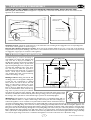
Andalusia models : Simply lift off the frame. To re-fit, ensure the four mounting hooks engage the four corresponding holes
on the front of the appliance as shown in figure 1.
Kavachi, Piano, Valeria and Cascara models : First, remove the retaining thumbscrews (one on each side of the appliance).
Simply lift the frame upwards. Refitting is the reverse of removal. Ensure the cut-outs in the bottom of the frame support brack-
ets engage the support pins on each side of the appliance.
Focal Point Fires plc. assumes absolutely no
responsibility for injuries and damages that
may occur due to improper installation or
handling. The appliance should not be installed
until all wet plastering and/or dry wall sand-
ing and wall painting has been completed. Do
not block the ventilation holes of the appli-
ance. The wall onto which the appliance is
installed must be flat. Install only on a vertical
surface. Avoid sloped surfaces. Installation
onto anything other than a vertical wall may
result in fire, damage or injury.
Marking Positions: Having selected the final
mounting position for the appliance, taking into
account the site requirements as detailed
above, the fire can now be fixed to the wall.
There are three fixing positions, two upper
“hanging” positions, and one lower positions.
Refer to Fig 3 for details. The two upper posi-
tions are located 85mm down from the top
edge of the top frame, and are spaced 350mm
apart about the centre line of the appliance. Once these have been marked the lower fixing position
can then be marked. This is 395mm vertically below the upper fixing positions, on the appliance centre
line. See Fig 3. Use a spirit level to ensure that the upper positions are horizontally aligned.
Wall Fixings: If the appliance is to be mounted on the inner leaf of a conventional cavity wall or a
solid wall, drill three holes to a depth of 42mm using a 8mm masonry bit. Insert the wall-plugs pro-
vided. If the appliance is to be mounted on a dry lined wall or timber framed construction, then spe-
cial cavity screw fixings will be required, that are not supplied with this product (see figure 4). Insert 2 x 40mm long fixing screws into
the upper two wall-plugs, taking care to leave the screws protruding approximately 6mm from the wall. Now hang the appliance onto
these upper screws through the two keyhole shaped holes in the upper brackets on the back panel of the appliance. Insert the lower
fixing screw into the lower wall plug through the corresponding fixing hole in the lower part of the back panel. Do not tighten fully.
Before tightening the wall mounting screws fully, at this stage it is recommended to check the horizontal alignment of the appliance
with a spirit level, as small adjustments can still be made if necessary. When this has been checked, tighten all four fixing screws fully.
To access the upper fixing screws insert a screwdriver through the access holes in the front face of the heater casing.
8.0 FIXING THE APPLIANCE
Figure 1
Figure 2
Andalusia frame mounting points
Kavachi, Piano, Valeria and Cascara models
1.Remove retaining
Thumbscrews
2.Lift frame away
from supporting pins
350mm
Lower fixing
point
Upper fixing points
C
L
395mm
Figure 3
© 2010 Focal Point Fires plc.
Figure 4

Peel off any remaining protective plastic coatings on the front and rear frame, backpanel and any other surfaces.
Unpack the pebbles and arrange them over the fuel bed. The final pebble arrangement can only be done later when the appliance
lamps are switched on. For the best visual effect, do not push the pebbles up against the back panel, leave a gap of approximate-
ly 40mm between the back panel and the pebbles. This allows light to shine up through the cut outs and illuminate the back panel.
READ ALL INSTRUCTIONS BEFORE USE!
Check that the fan outlet, mounted underneath the opening at the top, is not covered or obstructed in any way, and ensure the power
to the fire is switched on. The appliance is controlled using four switches mounted underneath the opening at the right hand side.
To operate the fire in any of the above modes, the left hand switch marked (OI) must be switched to the “on” position. To oper-
ate the fire, the left switch must be turned on first, followed by the second switch to start the blower, if required. To obtain heat
from the appliance, the I switch must then be operated for LOW heat, followed by the II switch for the HIGH heat setting.
The appliance can be switched off at any time, irrespective of the particular mode selected, by simply switching the left hand switch
marked (OI) to the “off” position. It is also recommended to unplug the power supply cable at the supply outlet when not in use.
This appliance has a safety cut-out system fitted which will activate if the air inlets or outlets are obstructed. For safety reasons
the fire WILL NOT switch on again automatically. NOTE: The visual light effect will remain operational if the cut-out is activated,
only the fan heater is prevented from operating.
The following procedure must be carried out before the fire can be operated again:
Unplug the power supply cable at the outlet socket and place all switches to off at the appliance. Leave the fire OFF for a period
of not less than 10 minutes, ensuring any obstructions are removed. Plug in the power supply cable at the outlet socket, and then
switch on at the appliance.
If the appliance fails to operate correctly, repeat the above procedure. If an attempt to switch on is made before the safety cut-out
has reset, the heaters may cut-out for a further period of time. If the sequence has been followed correctly and the heaters still fail
to function, check the power supply cable plug is plugged in to the outlet socket. If this is not the cause, call an electrician.
ALWAYS DISCONNECT THE APPLIANCE FROM THE MAINS SUPPLY OUTLET SOCKET BEFORE UNDERTAKING ANY MAINTENANCE!
Excluding lamps and fuses, use only genuine spare parts available from your supplier. Replacement lamps must be of the same
wattage and specification as those stated in Section 3.0 Appliance Data.
Replacing the light bulbs.
1. Switch off at the appliance, and then disconnect the appliance at the outlet socket.
2. Remove the decorative facia from the appliance (see section 7.0).
3. Remove the light bulb(s). Note that the bulbs have a conventional bayonet fitting. Replace with a new bulb(s). Refer to section 14.0.
4. Replace the decorative facia.
5. Reconnect electrical supply and check for correct operation of lamps and both spinner assemblies.
ALWAYS DISCONNECT THE APPLIANCE FROM THE MAINS SUPPLY OUTLET SOCKET BEFORE UNDERTAKING ANY MAINTENANCE!
There are no specific requirements for care, other than regular cleaning of the general appliance. A wipe with a dry cloth is nor-
mally sufficient. DO NOT use abrasive cleaners as they can damage the finish. Stainless steel parts (where applicable) may be
cleaned using an appropriate metal cleaner or baby oil. Test on a hidden part of the stainless steel before cleaning. Clean only in
the direction of the grain. Mirror surfaces may be cleaned using normal glass cleaner.
Refer to Section 3.0 Appliance Data for lamp and fuse specification. Excluding lamps and fuses, use only genuine manufacturers
spare parts available from your supplier. We recommend ‘GE Fireglow’ replacement lamps. Do not use ‘Maxim’ branded lamps as
these have been found to cause discolouration of the white inner firebox.
9.0 PLACING THE PEBBLES
GB IE
As our policy is one of continuous improvement and development, we therefore hope that you will understand we must retain the right to amend details and/or specifica-
tions without prior notice.
4
© 2010 Focal Point Fires plc.
13.0 CLEANING
10.0 OPERATING THE FIRE
11.0 SAFETY CUT-OUT SYSTEM
12.0 MAINTENANCE
14.0 SPARES
Waste electrical products should not be disposed of with household waste. Please recycle where facilities exist. Check with your local authority or retailer for recycling advice.
F860579
• The left hand switch marked (0I), controls the main power to the appliance and switches on the visual light display. This fea-
ture can be used independently of the heating features.
• The next switch marked (
*
) operates the fan blower without heat, and can be used for cool air circulation. However for this
feature, the main power switch (0I), must also be in the “on” position.
• The next switch with a “single bar” marked (I) operates the low heat, (1kW), setting.
• The switch with “ two single bars” marked (II) operates the high heat, (2kW), setting.
-
 1
1
-
 2
2
-
 3
3
-
 4
4


FocalPoint Kavachi Electric Wall Mounted User manual
- Type
- User manual
Ask a question and I''ll find the answer in the document
Finding information in a document is now easier with AI
Related papers
-
Focal Point UMBRIA User manual
-
-
-
-
-
-
FocalPoint MONET ELECTRIC ECO User manual
-
Focal Point Valeria User manual
-
-
Other documents
-
-
Solistone 6038SAM User manual
-
-
-
-
-
-
-
-