Page is loading ...

© 2015 Focal Point Fires plc.
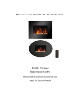
INSTALLATION & USER INSTRUCTIONS
All instructions must be handed to the user for
safekeeping.
MODELS COVERED BY THESE INSTRUCTIONS
Ebony LED Electric Fire
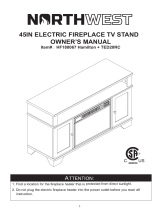
WALL MOUNTED ELECTRIC FIRE
Please note: Except where otherwise stated, all rights,
including copyright in the text, images and layout of this
booklet is owned by Focal Point Fires plc. You are not
permitted to copy or adapt any of the content without
the prior written permission of Focal Point Fires plc.
1
Revision B - 09/15
GB IE
Focal Point Fires plc.
Christchurch, Dorset BH23 2BT
Tel: 01202 499330
Fax: 01202 499326
www.focalpointfires.co.uk
Email: [email protected].uk
Questions or problems with your appliance?
Don’t take it back to the store
just give us a call on 01202 588601 we’re here to help
lines open between 9am and 5pm, Monday to Friday
EBONY LED ELECTRIC FIRE

© 2015 Focal Point Fires plc.
I N S TA L L AT I O N & U S E R I N S T R U C T I O N S
2
GB IE
Section Contents Page No.
1.0 Important Notes 2
2.0 Installation Requirements 3
3.0 Appliance Data 3
4.0 Component Checklist 3
5.0 Site Requirements 3
6.0 Clearances To Combustibles 4
7.0 Unpacking The Appliance 4
8.0 Installation Wall Mounted 4
Section Contents Page No.
9.0 Operating the Appliance 7
10.0 Safety Cutout System 8
11.0 Cleaning and Maintenance 9
12.0 Troubleshooting Guide 9
13.0 Servicing 9
14.0 Appliance Dimensions 10
15.0 Guarantee - Terms and Conditions 10
1.0 IMPORTANT NOTES
IMPORTANT - THESE INSTRUCTIONS SHOULD BE READ CAREFULLY
AND RETAINED FOR FUTURE REFERENCE.
When using this electrical appliance, basic precautions should be followed to reduce the risk
of fire, electric shock and injury to person, including the following:
• This heater must be used on an AC supply only and the voltage marked on the heater’s
rating label must correspond to the supply voltage.
• DO NOT switch the appliance on until it is properly installed as described in this
manual.
• This appliance can be used by children aged from 8 years and above and persons with
reduced physical, sensory or mental capabilities or lack of experience and knowledge if they
have been given supervision or instruction concerning use of the appliance in a safe way and
understand the hazards involved. Children shall not play with the appliance. Cleaning and
user maintenance shall not be made by children without supervision.
• Children of less than 3 years should be kept away unless continuously supervised.
Children aged from 3 years and less than 8 years shall only switch on/off the appliance
provided that it has been placed or installed in its intended normal operating position and
they have been given supervision or instruction concerning use of the appliance in a safe
way and understand the hazards involved. Children aged from 3 years and less than 8 years
shall not plug in, regulate and clean the appliance or perform user maintenance.
• CAUTION: Some parts of this product can become very hot and cause burns.
Particular attention has to be given where children and vulnerable people are present.
• If the supply cord is damaged, it must be replaced by the manufacturer, its service agent or
similarly qualified persons in order to avoid a hazard.
• The heater must not be located immediately below a socket-outlet.
• DO NOT use this heater in the immediate surroundings of a bath, a shower or a
swimming pool.
• WARNING: In order to avoid overheating, do not cover the heater.
• DO NOT use this heater with a programmer, timer, separate remote-control system or
any other device that switches the heater on automatically, since a fire risk exists if the
heater is covered or positioned incorrectly.
• CAUTION: In order to avoid a hazard due to inadvertent resetting of the thermal
cutout, this appliance must not be supplied through an external switching device, such as a
timer, or connected to a circuit that is regularly switched on and off by the utility.
• WARNING: This heater is not equipped with a device to control the room
temperature.Do not use this heater in small rooms when they are occupied by persons not
capable of leaving the room on their own, unless constant supervision is provided.
• Keep furniture, curtains and other fabric material away from the appliance.
• DO NOT leave the appliance unattended during use.

4.0 COMPONENT CHECKLIST
3
© 2015 Focal Point Fires plc.
3.0 APPLIANCE DATA
Weight (kg): 15kg
Dimensions: H 620 x W 520 x D 148 (mm)
Supply Voltage: 220~240V AC, 50Hz
Fuse Rating: 13 Amp
Heating Elements: 1500W
Lighting: LED
This fire is fitted with LED’s (Light Emitting Diode) in place of conventional bulbs. LED’s generate the same light levels as
conventional bulbs, but use a fraction of the energy consumed. LED’s are maintenance free and will not require replacing during
the life of the product.
Quantity Description
1 Heater unit
1 Decorative glass fascia
1 Remote control handset
2 Metal fixing plates
5 Wall plugs
5 Fixing screws
4 Metal plate screws
5.0 SITE REQUIREMENTS
It should be noted that the appliance creates warm convected air currents. These currents move heat from the room
surroundings to, and up the wall surfaces adjacent to the heater.
Installing the heater next to these types of wall coverings or operating the heater where impurities in the air, (such as tobacco
smoke) exist, may slightly discolour wall finishing.
If the appliance is to be mounted on a dry lined or timber framed construction then the integrity and ability of the wall to
carry the weight of the appliance must be confirmed. It is important in these circumstances that any vapour barrier and/or
structural members of the house frame are not damaged.
If you are unsure of the ability of the wall to carry the weight and/or which type of wall fixing to use, you should take
professional advice and obtain the correct fixings. Alternatively, find a more suitable wall location.
DO NOT
• mount on a ceiling or floor
• recess any part of the appliance into the wall, or run the supply cable under carpets
• site any electrical equipment e.g. plasma screen TV sets etc, on the wall below the appliance.
The appliance is supplied with a pre-wired three pin plug (13 Amp fuse rated) and 1.8 metres of electrical cable. It is therefore
necessary for a suitable electrical socket to be located within this distance and be easily accessible. This appliance is designed to
be wall hung, using the wall fixtures/fixings provided. DO NOT recess any part of appliance into the wall. This appliance is
suitable for installation in static holiday/park homes.
2.0 INSTALLATION REQUIREMENTS
• From time to time, check the cord for damage. Never use the appliance if the cord
or any part of the appliance shows signs of damage.
• DO NOT run the mains cable under carpets, rugs etc.
• DO NOT cover or obstruct the heater in any way. Overheating will result if it is
accidentally covered.
• Never immerse the product in water or any other liquids.
• DO NOT use the appliance outdoors.
• Before cleaning the appliance, ensure it is unplugged from the power and that it is
completely cool.
• DO NOT clean the appliance with abrasive chemicals.
• Never use accessories that are not recommended or supplied by the manufacturer. It
could cause danger to the user or damage to the appliance.
• DO NOT insert or allow foreign objects to enter the inlet or outlet vents as this may
result in electric shock, fire or damage to the appliance.
• DO NOT install the fire using an extension cord.
• Unplug from the mains supply if the appliance is not to be used for long periods.
1.0 IMPORTANT NOTES - CONTINUES
GB IE

5.0 SITE REQUIREMENTS - CONTINUED
IMPORTANT - PLEASE READ COMPLETELY THROUGH THE INSTRUCTIONS AND VERIFY THAT ALL LISTED
PARTS ARE PRESENT BEFORE ASSEMBLY.
7.0 UNPACKING THE APPLIANCE
C
a
ut
io
n:
T
his applia
nc
e is hea
v
y.
A
l
w
ay
s seek a
ssist
a
nc
e w
hilst
unpa
c
king
a
nd/
o
r
dur
ing
inst
a
lla
t
io
n.
P
lea
se rea
d
a
ll t
he inst
r
uc
t
io
ns bef
o
re c
o
nt
in
uing
t
o
unpa
c
k o
r
inst
a
ll applia
nc
e
.
B
e
for
e
s
tar
ti
n
g th
e
i
n
s
tal
l
ati
on
of
th
i
s
fi
r
e
p
l
ac
e
, p
l
e
as
e
r
e
ad
th
e
fol
l
o
w
i
n
g:
1
. T
h
e
i
n
s
tal
l
ati
on
s
h
ou
l
d
b
e
c
ar
ri
e
d
ou
t by
two ad
u
l
ts
to av
oi
d
i
n
j
u
ry
or d
am
age
. I
f
for an
y
r
e
as
on
i
t i
s
c
on
s
i
d
e
r
e
d
too h
e
av
y
,
pl
e
ase
obtai
n assi
stance.
2. Whe
n l
i
f
ti
ng the
fi
r
e
pl
ace, alwa
ys k
e
e
p y
our back
strai
ght. Be
nd
y
our l
e
gs and
not y
our back
.
Av
oi
d
twi
sti
ng at the
wai
st. I
t i
s
be
tte
r to r
e
posi
ti
on y
our fe
e
t.
3.
Av
oi
d
uppe
r bod
y /
top he
avy be
nd
i
ng.
Alwa
ys be
nd
f
rom
the
k
ne
e
s rathe
r than the
wai
st. Do not l
e
an forward
or si
d
e
ways
whi
l
e
hand
l
i
ng the
he
ate
r
.
4.
Alwa
ys gri
p the
he
ate
r wi
th the
pal
m
of
the
hand
. Do not use
the
ti
ps of
fi
nge
rs for support.
5.
Alwa
ys k
e
e
p the
he
ate
r as cl
ose
to the
bod
y as possi
bl
e. T
hi
s wi
l
l
m
i
ni
m
i
ze
the
canti
l
e
v
e
r acti
on.
6. U
se
gl
o
v
e
s to pr
o
vi
d
e
add
i
ti
onal
gri
p.
7. U
npack
the
pack
age
and
l
i
f
t the
pr
od
uct ge
ntly out of
the
box, put i
t on a f
l
at surf
ace
wi
th the
f
r
ont pane
l
f
aci
ng up.
4
© 2014 Focal Point Fires plc.
GB IE
8.0 INSTALLATION WALL MOUNTED
CAUTION: DO NOT CONNECT THE APPLIANCE TO THE
ELECTRICAL SUPPLY AT THIS TIME.
Focal Point Fires plc. assumes absolutely no responsibility for injuries and damages
that may occur due to improper installation or handling.
Remove any protective film coatings from the finished/decorative surfaces of the
appliance, if any. After having selected the final mounting position of the appliance
taking into account the integrity of the wall the firebox of the appliance may be
secured to the wall.
To ensure customer safety, be sure to design the installation so that the strength of
both the wall and any wall fixings used are sufficient. The appliance should not be
installed until all wet plastering and/or dry wall sanding and wall painting has been
completed. Do not block the ventilation holes of the appliance. The wall onto
which the appliance is installed must be flat. Install only on a vertical surface. Avoid
sloped surfaces. Installation onto anything other than a vertical wall may result in
fire, damage or injury.
If the appliance is to be mounted on the inner leaf of a conventional cavity brick
wall, or a solid wall, then the wall plugs and fixing screws provided may be used.
Depending on the condition of the wall it may be necessary to use additional fixings.
In this situation, any additional fixings and wallplugs should be of the same size and
type as the ones provided.
The wall where the appliance is to be
installed must be capable of
long-term support of the total load of
the appliance. Measures should also
be taken to ensure sufficient strength
to withstand the force of
earthquakes, vibration and other
external forces. Plasterboard alone is
not considered to be a structural
material. It is not recommended to
rely on plasterboard fixings alone to
support the weight of the appliance.
WARNING
If the appliance is to be mounted on a dry lined wall or a timber framed construction wall then efforts should be made to fix
in at least two positions vertically, into one of the wooden studs, or supporting wooden members of the wall using the fixing
screws provided. If this is not achievable then the wall should be strengthened using appropriate building materials.
It is important that the following clearances are maintained from the appliance to combustible materials. These clearances are
dependent on the mounting location as defined below:
• The minimum distance from the top of the appliance to a ceiling is 300mm
• The minimum distance from the bottom of the appliance to the floor is 300mm
• The minimum distance to the sides of the appliance is 200mm
• The minimum distance to the front of the appliance is 500mm
6.0 CLEARANCES TO COMBUSTIBLES
• site in a position where curtains or drapes could cover the appliance, or other soft materials could cover e.g. below a coat
rack
• site behind an opening door where mechanical impact/damage could occur
• site where the supply cable would become a trip hazard
• sit, stand or forcefully pull on the appliance
• obstruct, cover or force items into the openings
• use the heater to dry clothes
• site/use in an outdoor location(s)

8.0 INSTALLATION WALL MOUNTED - CONTINUED
GB IE
Installing the wall plugs into the wall.
1. Drill 5 holes (8mm diameter, 40mm deep) into wall.
2. Insert the supplied wall plugs into the drilled holes.
3. Please refer to the diagram for hole locations.
Please note: Before drilling into walls, always check that
there are no hidden wires, pipes, etc.Make sure that
screws and wall plugs supplied are suitable for
supporting the unit in your surface. Consult a qualified
person if you are not sure.
5
© 2015 Focal Point Fires plc.
Installing the fixing screws into the wall.
1. Insert three of the fixing screws into the top three wall plugs.
Installing the metal fixing plates to the back of the fire.
1. Carefully place the fire on it’s front.
2. Align the metal fixing plates (A) with the screw holes located
at the back of the fire box.
3. Use two of the metal plate screws to fix each of the metal
fixing plates to the firebox.
4. Ensure the metal fixing plates are securely attached.

8.0 INSTALLATION WALL MOUNTED - CONTINUED
GB IE
6
© 2015 Focal Point Fires plc.
Securing the fire to the wall.
1. Insert one the fixing screws into the hole in each of the
metal fixing plates.
2. Fully tighten the screws to secure the fire to the wall.
3. Ensure the fire is secured to the wall.
Hanging the firebox onto the wall.
1. Check to make sure the fixing screws are securely
attached to the wall.
2. Lift the firebox and hang on the fixing screws.
Installing the front fascia.
1. Hold the glass fascia securely and hang it onto the
firebox hooks, which are located on both sides of the
firebox.
2. The glass fascia should be secured on all four firebox
hooks.
3. Check to make sure the glass fascia is securely in place.

8.0 INSTALLATION WALL MOUNTED - CONTINUED
GB IE
7
© 2015 Focal Point Fires plc.
Securing the front fascia.
1. Locate the hole on both left and right sides and insert a
screw.
through the hook, into the fireplace insert.
2. Tighten screw to pass it through the hook, on both
sides.
3. Ensure the front fascia is secure.
Note: Tighten up the screw carefully, to avoid damage to
the front panel.
9.0 OPERATING THE APPLIANCE
On the top right side plate of the Electric there is the control panel
(see figure 1). This panel contains the buttons to properly operate the
electric fire. The buttons on the control panel on the side of the
Electric Fire and the Remote Control function in the same way. The
remote control has an effective range of up to 13 feet.
To turn unit on, press the main ON/OFF switch from "0" to "I". The
switch will illuminate and it will beep one time. The unit will go into
standby mode. To turn it off, please press the switch from "I" to "0".
Now you can use either buttons next to the main ON/OFF switch
or remote control to control the appliance.
1. On/Off
2. Heater low (750W)
3. Heater high (1500W)
4. Flame effect level up
5. Heater off
6. Flame effect level down
2.
3.
1.
4.
6.
Figure 1.
5.

8
9.0 OPERATING THE APPLIANCE - CONTINUED
GB IE
© 2015 Focal Point Fires plc.
Remote Control
The fire is supplied with an IR multifunction remote.
Before the remote will operate the plastic insulating sheet needs
to be removed.
Battery Replacement
Battery Requirements: CR2025
1. Locate and remove the battery bracket.
2. The battery has two sides, one with a button feature, and the
other is flat.
3. Insert the battery with the button side down into the battery
bracket, making sure the battery is firmly seated.
Power Button
Press this button once to turn on the fire and press it again to turn it back to
standby mode.
Heater Buttons
The heater buttons allows you to chose from either 750W or 1500W of heat
depending on which button you press. The low button will give you 750W of heat and
the high button gives you 1500W of heat.
Heater Off Button
This button will turn off the electric fan heater.
Flame Effect Buttons
The flame effect buttons allows you to adjust the flame effect levels by pressing the
buttons. The level up button will allow you to increase the flame effect and the flame
effect level down will allow you decrease the flame effect level.
10.0 SAFETY CUT-OUT SYSTEM
NOTE: The LED display panel will remain operational if the cut-out is activated, only the fan heater elements are prevented
from operating.
This product has one non-self-resetting overheat protection device (thermal cut-out) which will activate if the air inlets or outlets
are obstructed. For safety reasons the fire will NOT switch on again automatically, the following procedure must be carried out
before the fire can be operated.
NOTE: The visual effect will remain operational if the cutout is activated, only the fan heater is prevented from working.
Switch OFF the appliance at the wall socket or outlet. Leave the fire OFF for a period of no less than 10 minutes, ensuring all
obstructions are removed. Switch the appliance ON at the wall. Ensure the appliance is turned ON at the control switches. If
the fire fails to operate correctly, repeat the above procedure. If an attempt to switch on the appliance is made before the safety
cutout has reset, the appliance may cutout for a further period of time. If the sequence has been followed correctly and the
appliance still fails to function, check the fuse in the wall outlet. If this is not the cause, call an electrician or maintenance engineer.

12.0 TROUBLESHOOTING GUIDE
9
Fire is not switching on Ensure mains switch is on
Replace the fuse in the plug
Logs glow but flame effect does not work
Check to see if the spinning motor is working. If not contact
Focal Point Fires
Heater doesn't work, but Power and Heater
switches / buttons are in the "ON" position
Turn all switches / buttons to the "OFF" position and unplug
the unit from the wall outlet for 5 minutes.
After 5 minutes plug the unit back into wall outlet, and
operate as normally.
Fire seems noisy There is a level of noise when the flame effect is in use,
caused by a motor that helps generate the effect. This noise
will be heard when there is no other background noise.
There is a higher level of noise associated with the heater
motor; this is due to the air flow required when heat has
been selected.
Remote is not operating Check or replace batteries.
© 2015 Focal Point Fires plc.
13.0 SERVICING
There are no internal user serviceable parts.
Check regularly for security of wall fixings as appropriate. Also check security of supply cable and connections. If the supply cable
becomes damaged, it must be replaced by a service agent or competent person, such as a qualified electrician.
This appliance is supplied with a 3 pin plug fitted with a 13 Amp fuse. Should the fuse require replacing, it must be replaced
with a fuse rated at 13 Amp. In the event of the mains plug being removed/ replaced for any reason, please note :
IMPORTANT: The wires in the mains lead are coloured in accordance with the following code:
Blue - Neutral
Brown - Live
Green/ Yellow - Earth
As the colours of the wires in the mains lead of this appliance may not correspond
with the colour markings identifying the terminals in your plug, proceed as follows.
The blue wire must be connected to the terminal marked with an N or coloured
black. The brown wire must be connected to the terminal marked with an L or
coloured red. The green/yellow wire must be connected to the earth terminal
which is marked with an E or with the earth symbol. WARNING: Never connect
live or neutral wires to the earth terminal of the plug.
NOTE: If a moulded plug is fitted and has to be removed take great care in
disposing of the plug and severed cable, it must be destroyed to prevent engaging
into a socket.
Refer to Section 2.0, Appliance Data for fuse specification. Excluding fuses, use only
genuine manufacturers spare parts available from your supplier.
Figure 15
ALWAYS DISCONNECT THE APPLIANCE FROM THE MAINS SUPPLY OUTLET
SOCKET BEFORE UNDERTAKING ANY CLEANING OR MAINTENANCE!
For general cleaning use a soft clean duster - never use harsh abrasive or cleaners. The glass viewing screen should be cleaned
carefully with a soft cloth.
If in doubt consult a qualified electrician. Refer to Section 3.0 Appliance Data for fuse specification. Excluding fuses, use only
genuine manufacturers spare parts available from your supplier.
Replacing the remote control battery:
When the battery becomes weak, the range of the remote control becomes shorter. Replace the battery with a new CR2025
lithium battery.
Note: Keep the lithium battery out of the reach of children.
11.0 CLEANING AND MAINTENANCE

15.0 GUARANTEE - TERMS AND CONDITIONS
10
F861290
Waste electrical products should not be disposed of with household waste. Please recycle where facilities exist. Check with your local authority or retailer for recycling advice.
As our policy is one of continuous improvement and development, we therefore hope that you will understand we must retain the right to amend details and/or specifications without prior notice.
© 2015 Focal Point Fires plc.
Registration is not required.
1. For any claim to be made within the 3 years from date of purchase you will be required to provide and supply us with your original proof
of purchase.
2. Purchase(s) must be made through an authorised stockist/retailer.
During the guarantee period any product or component which is proved to be faulty or defective in manufacture, will be repaired or replaced
free of material and labour charges, providing that we have authorised or carried out the repair or replacement.
We will not accept or reimburse the costs of any third party who undertakes any work carried on the product or fits parts, unless we have
approved such work in advance of it being carried out.
The guarantee period will not be extended even if we repair or replace any product or part.
For all electric fires purchased the 3 year guarantee commences from the date of purchase, providing that you can supply the proof of
purchase. This does not cover consumable items such as pebbles, coals or light bulbs. Purchase(s) must be made through an authorised
stockist.
Making a claim
Making a claim is easy. If you wish to make a claim under our guarantee and all the terms and conditions for your product have been met
then please submit the following information for the attention of the 3G Service Department to the address below. Alternatively, you can
email or fax.
Focal Point Fires, 3G Service Department, Reid Street, Christchurch, Dorset, BH23 2BT.
Email: [email protected].uk,
Fax. 01202 588639.
Details required:
1. Name, full address including postal code and contact telephone number.
2. A copy of your proof of purchase e.g. receipt or bank statement.
Please note that this does not affect your statutory rights.
14.0 APPLIANCE DIMENSIONS
Dimensions in mm
GB IE
/