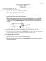
Holman PC18 Operating instructions
- Category
- Cookers
- Type
- Operating instructions

PIZZAS OF EIGHT PIZZA SYSTEMS
OPERATOR'S MANUAL
MODEL PC18
FOR SERVICE INFORMATION
U.S. AND CANADA CALL: 1-800-807-9054
24 HOURS/DAY 7 DAYS/WEEK
TABLE OF CONTENTS
UNCRATING AND INSPECTION PAGE 1
ASSEMBLY AND INSTALLATION PAGE 1, 2
STACKING INSTRUCTIONS PAGE 3
OPERATION PAGE 4
COOKING PROCEDURES PAGE 4
CLEANING PROCEDURES PAGE 5, 6
TROUBLESHOOTING GUIDE PAGE 6, 7, 8
MAINTENANCE PROCEDURES PAGE 9, 10, 11
PARTS LIST PAGE 12
DRAWINGS
ADJ. HEAT SHIELDS, FRONT VIEW PAGE 2
UNLOAD TRAY PAGE 2
HEAT REFLECTOR/CRUMB TRAYS PAGE 5
REMOVING THE CONVEYOR BELT PAGE 5
BELT SUPPORT SYSTEM PAGE 5
DRIVE SYSTEM PAGE 8
HEATER TUBE INSTALLATION PAGE 9
COMPONENT ARRANGEMENT PAGE 11
WIRING DIAGRAM
CONVEYOR BELT CLEANING PROCEDURES
PAGE 13
PAGE 14
2M-HG0106 REV. 5/4/2005

PAGE 1
PIZZAS OF EIGHT PIZZA SYSTEMS
OPERATOR'S MANUAL
MODEL PC18
UNCRATING AND INSPECTION
Unpack unit and components from container. Remove all visible packing material, inspect unit for damage. If
damage is discovered, file a claim immediately with the carrier that handled the shipment.
The following should be included in the container:
A. 1 ea. Baking oven with heaters with conveyor belt in place. Remove heating element shipping
supports.
B. 1 ea. Stainless Steel Unload Tray and 4 ea. 2 ½ “ Metal Legs.
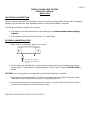
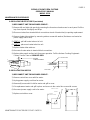
ASSEMBLY AND INSTALLATION
A. Attach legs by screwing into weld nuts, as shown
B. Anti Skid pads are available at no charge and may be adhered to the foot section of each leg to
prevent sliding. Call the Holman Cooking Equipment Factory Service Team at 1-800-807-9054 for
details.
CAUTION: Use of these pads are not approved by the National Sanitation Foundation.
C. Install unit in its operating position. The load & unload ends must be at least 6" from any vertical
combustible surfaces. Allow sufficient space for operating personnel.
D. Have an electrician connect input power to the unit(s) in accordance with local electrical codes. A
connection terminal block is inside the left side cavity.
ASSEMBLY AND INSTALLATION CONT. ON PAGE 2
INSERT LEG BY SCREWING
INTO WELD NUT ON BOTTOM
OF UNIT.

PAGE 2
PIZZAS OF EIGHT PIZZA SYSTEMS
OPERATOR'S MANUAL
MODEL PC18
ASSEMBLY AND INSTALLATION (CONT)
WARNING
: MAKE SURE ALL INPUT POWER IS OFF BEFORE INSTALLING/REMOVING ANY PARTS.
WARNING
: BEFORE INSTALLING UNIT(S), CHECK WITH LOCAL POWER COMPANY TO DETERMINE
ACTUAL VOLTAGE AT JOB SITE. NEVER PLUG A 208 VOLT UNIT INTO 240 VOLTS OR A
240 VOLT UNIT INTO 208 VOLTS.
WARNING;
BE ABSOLUTELY SURE THE GROUND CONNECTION FOR THE RECEPTACLE IS
PROPERLY WIRED. NEVER CONNECT UNIT TO POWER WITHOUT PROPER GROUND
CONNECTIONS. IMPROPER GROUND MAY RESULT IN SEVERE INJURY OR FATALITY.
E. Before applying input power to the unit(s) check heating elements for breakage, do not apply power to
the unit(s) if a broken tube is found. If no broken tubes are found apply input power by switching the
master on/off toggle switch to the ON position. Turn both heat controls and conveyor belt speed
control to the maximum setting and check all heater tubes and conveyor for proper operation.
F. Allow approximately 5 to 8 minutes for the fan cooling system to come on, check the air intake area as
noted below and be sure that there is a sufficient flow of air into the control box.
G. If all heaters and conveyor system are operating properly, switch the master on/off switch to the OFF
position and allow unit to cool, the fan will continue to circulate cool air through the unit until the
internal temperatures have been decreased.
H. If a problem is discovered during start up procedures, immediately switch the master on/off switch to
the OFF position and notify the Holman Cooking Equipment Factory Service Team at 1-800-807-9054
24 hours 7 days a week, service will be arranged for you.
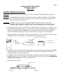
I. Install unload tray as shown.
AIR INTAKE LOCATED
ON BOTTOM CONTROL
BOX COVER.
ADJUSTABLE HEAT SHUTTER
UPPER POSITION
LOWER POSITION
CRUMB TRAYCRUMB TRAY
UNLOAD TRAY

PAGE 3
PIZZAS OF EIGHT PIZZA SYSTEMS
OPERATOR'S MANUAL
MODEL PC18
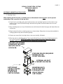
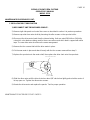
ASSEMBLY AND INSTALLATION (CONT.)
F. Stacking Ovens
When stacking two PC18 ovens, a stacking spacer with external air duct must
be used to prevent
overheating of the control box in the top oven.
1) If cart is to be used with units, place bottom unit on cart and align leg hole of unit to holes in top
portion of cart. Insert 3/8" bolts through cart and into leg holes to secure bottom unit to cart as
shown below.
2) Place stacking spacer on top of the bottom oven with internal air duct facing up and toward the rear
of the oven.
3) Mount external air duct on stacking spacer as shown below. External air duct must be installed for
cooling system of top unit to function properly.
4) Screw cap screws (4ea.) into leg holes on top oven (see fig. #1 below).
5) Place top oven on stacking spacer. Cap screws will set into cut outs in top of stacking spacer to
lock unit into position. (NOTE) Air intake of top unit must fit over the internal air duct of
stacking spacer to allow airflow into the control box of the top oven.
BOTTOM UNIT
CAN BE COUNTER
MOUNTED OR
PLACED ON A
CART AS SHOWN
MOUNTING BOLTS
FOR BOTTOM UNIT
SCREW INTO LEG
HOLES THOUGH
CART FRAME.
STACKING SPACER (REQUIRE
D
MOUNTS ON TOP
OF BOTTOM OVEN.
EXTERNAL AIR DUCT
MOUNTS ON SPACER.
TOP UNIT- CAP SCREWS
SCREW INTO LEG HOLE.
UNIT SITS ON TOP
OF SPACER.

PAGE 4
PIZZAS OF EIGHT PIZZA SYSTEMS
OPERATOR'S MANUAL
MODEL PC18
OPERATION
A. Switch master on/off switch to the ON position and turn top and bottom heat controls to number 10,
turn conveyor speed control to fastest time setting.
B. Allow 10 to 15 minutes for unit(s) to warm up.
C. Baking in these units is a combination of heat and belt speed. Some foods may require more top heat
or vice versa; other foods may require low top and bottom heat and slow belt speeds. Every product
should, therefore, be tested using the separate top and bottom heat controls and the variable speed
Control to arrive at the correct balance of heat and belt speed. When changing heat and/or belt speed
settings allow approx. 5 minutes for the oven to stabilize itself at the new settings.
COOKING PROCEDURES
THE FOLLOWING SUGGESTED SETTINGS FOR THE VARIOUS PRODUCTS LISTED ARE
INTENDED TO ASSIST THE USER OF THESE OVENS WITH ARRIVING AT THE CORRECT
BALANCE OF HEAT AND SPEED. SOME ADJUSTMENTS MAY STILL HAVE TO BE MADE TO BOTH
HEAT AND SPEED DEPENDING ON THE PRODUCTS FRESHNESS AND/OR THICKNESS AND
DENSITY.
PRODUCT
TOP HEAT BOTTOM HEAT BELT SPEED
PIZZA
12" FRESH 350°F 450°F 8 MINUTES
16" FRESH 300°F 450°F 12 MINUTES
12" BLANCHED 300°F 400°F 6 MINUTES
16" BLANCHED 300°F 400°F 8 MINUTES
12" FROZEN 300°F 300°F 8 MINUTES
16" FROZEN 350°F 350°F 12 MINUTES
SANDWICHES
MEAT/CHEESE 450°F 300°F 4 MINUTES
MEATBALL 500°F 350°F 2 MINUTES
BAGEL (OPEN) 500°F 400°F 2 MINUTES
COOKIES
1 TO 1 1/2 Oz 200°F 250°F 12 MINUTES
GARLIC BREAD
LIGHTLY SEASONED 500°F 500°F 2 MINUTES
FISH
SIZZLE PLATTER 400°F 500°F 6 MINUTES

PAGE 5
PIZZAS OF EIGHT PIZZA SYSTEMS
OPERATOR'S MANUAL
MODEL PC18
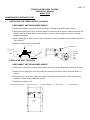
CLEANING PROCEDURES
Preventive maintenance for your conveyor oven consist of the following recommended cleaning procedures.
To keep your oven in its top operating condition, these steps should be performed daily or weekly as indicated.
NOTE:
LUBRICATION OF DRIVE CHAIN WITH A GRAPHITE BASED LUBRICANT IS REQUIRED AS PERIODIC
MAINTENANCE. CALL HOLMAN FACTORY SERVICE DEPARTMENT FOR DETAILS.
WARNING:
HIGH VOLTAGES ARE PRESENT IN THESE UNITS. BE SURE ALL INPUT POWER IS OFF
BEFORE SERVICING OR CLEANING UNIT.
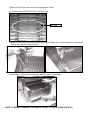
A. Remove load and unload trays (daily) as shown.
B. Remove the crumb trays from both load and unload ends of the oven (daily) as shown above, (DO
NOT CLEAN WITH CAUSTIC CLEANERS).
C. For lightly soiled conveyor surfaces a damp cloth or scotch pad can be used without removing the
conveyor belt. (daily)
D. For heavily soiled conveyor surfaces disconnect and remove the conveyor as shown and soak in hot
soapy water overnight (as required).
E. If you have removed the conveyor belt, then remove the conveyor support system as shown above
and clean with a scotch pad (as required).
CLEANING PROCEDURES CONT. PAGE 6
BELT SUPPORT ROD
COUPLER WILL SCREW
ONTO MOUNTING STUD
MOUNTING STUD
CRUMB TRA
Y
CRUMB TRA
Y
UNLOAD TRAY

PAGE 6
PIZZAS OF EIGHT PIZZA SYSTEMS
OPERATOR'S MANUAL
MODEL PC18
CLEANING PROCEDURES CONT.
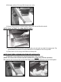
F. Check air intake area for dust and grease. To clean, remove the control box cover and wipe with a dry
cloth.
G. Re-assemble unit and check to be sure it is operating properly. Call the Holman Cooking Equipment
Factory Service Team at 1-800-807-9054 if the unit is not operating properly.
TROUBLESHOOTING GUIDE
A. UNIT WILL NOT HEAT, CONVEYOR WILL NOT TURN.
1) Be sure main circuit breaker is switched to the ON position and there is power at the outlet.
2) Check to see that the unit is connected to power and Master On/Off is switch to the ON position.
3) Be sure RESET BUTTON is pushed in (see below).
B. UNIT WILL NOT HEAT, CONVEYOR TURNS PROPERLY.
1) Check to see if top and bottom heat controls have been turned to the maximum setting.
2) Press heat limit reset button located on the front section of the control box as shown above. If this
reactivates the heater tubes, see section C below.
3) For further assistance call the Holman Factory Service Team at 1-800-807-9054.
TROUBLESHOOTING GUIDE CONT. ON PAGE 7
HEAT LIMIT SWITCH LOCATED
BENEATH FRONT EXTENSION.
CUTAWAY VIEW OF CONTROL BOX WITHOUT
CONTROL BOX COVER
CONTBOX.DS4
ON FRONT OF CONTROL BOX
CRUMB TRAYCRUMB TRAY

PAGE 7
PIZZAS OF EIGHT PIZZA SYSTEMS
OPERATOR'S MANUAL
MODEL PC18
TROUBLESHOOTING GUIDE CONT.
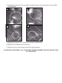
C. HEAT LIMIT SWITCH
Your conveyor oven is equipped with an automatically activated temperature limit switch which interrupts the
heater tube connections if the air temperature in the control box exceeds 190°F (88°C). This limit switch can be
reset manually by pushing the button in the center of the switch which is located as shown.
THE HEAT LIMIT SWITCH CAN BE ACTIVATED IF THERE IS NOT A PROPER AMOUNT OF AIR FLOW
BEING GENERATED BY THE COOLING FAN. IF THIS OCCURS:
1) DISCONNECT UNIT FROM POWER SOURCE.
2) Check to see if air intake area (openings in bottom center of control box) is free of dust, grease or
other obstructions.
3) Check to see if crumb trays (heat reflectors) are in place.
NEVER OPERATE UNIT WITHOUT CRUMB TRAYS IN POSITION AS THIS CAUSES OVERHEATING IN
THE CONTROL BOX.
TROUBLESHOOTING GUIDE CONT. ON PAGE 8
HEAT LIMIT SWITCH
CRUMB TRA
Y
CRUMB TRA
Y
UNLOAD TRAY

PAGE 8
PIZZAS OF EIGHT PIZZA SYSTEMS
OPERATOR'S MANUAL
MODEL PC18
TROUBLESHOOTING GUIDE CONT.
D. CONVEYOR WILL NOT TURN, UNIT HEATS PROPERLY.
1) DISCONNECT UNIT FROM POWER SOURCE.
2) Check to see if there are obstructions in the conveyor system that may cause a jam.
3) Check power supply for loose or disconnected wires.
4) Remove right side panel and drive motor sprocket, (see below) Manually move conveyor belt to
check for mechanical binding. If conveyor moves freely, call the Holman Cooking Equipment
Factory Service Team at 1-800-807-9054 as drive motor and/or speed control may have to be
replaced.
E. CONVEYOR TURNS AT ONE SPEED REGARDLESS OF SPEED CONTROL SETTING.
1) Call the Holman Factory Service Team at 1-800-807-9054 as conveyor speed control may have to
be replaced. (refer to page 10 for instructions on replacing the speed control).
F. COOLING FAN DOES NOT START.
1) Remove control box cover and check fan blade for obstructions.
2) Contact the Holman Factory Service Team at 1-800-807-9054 as the fan switch and/or fan motor
may have to be replaced.
DRIVE CHAIN
DRIVE SPROCKET
DRIVEN SPROCKET

PAGE 9
PIZZAS OF EIGHT PIZZA SYSTEMS
OPERATOR'S MANUAL
MODEL PC18
MAINTENANCE PROCEDURES
A. REPLACING HEATER TUBES (see below)
1) DISCONNECT UNIT FROM POWER SOURCE.
2) Remove left and right side panels by removing the three truss head screws in each panel. Pull the
top of each panel out slightly and lift up.
3) Disconnect wires from terminal block connections at end of heater tube(s) requiring replacement.
4) Remove heater tube retainer by removing retainer screw with washer (Retainers are located on
power supply side of unit).
5) GENTLY, pull old heater tube out of unit.
6) GENTLY, place new heater tube into unit.
7) Replace heater tube retainers.
8) Reconnect heater wires to terminal block connections.
9) Replace side panels and test unit for proper operation. Call the Holman Cooking Equipment
Factory Service Team at 1-800-807-9054.
B. REPLACING FAN MOTOR
1) DISCONNECT UNIT FROM POWER SOURCE.
2) Remove control box cover with fan motor.
3) Unplug power supply cord from fan motor.
4) Remove(4)screws which hold fan motor and grill to cover.
5) Put replacement motor and grill in place and secure to the control box cover with screws.
6) Reconnect power supply cord to fan motor.
7) Replace control box cover.
MAINTENANCE PROCEDURES CONT. PAGE 10
HEATER
TUBE RETAINERS
HEATER TUBE
SIDE PANEL
FAN MOTOR
SECURED BY 4 SCREWS
AIR INTAKE
CONTROL BOX COVER

PAGE 10
PIZZAS OF EIGHT PIZZA SYSTEMS
OPERATOR'S MANUAL
MODEL PC18
MAINTENANCE PROCEDURES CONT.
C. REPLACING BELT DRIVE MOTOR
1) DISCONNECT UNIT FROM POWER SOURCE.
2) Remove right side panel and control box cover as described in section A in previous procedure.
3) Remove sprocket from motor shaft by loosening the allen screws on the sprocket collar.
4) Disconnect the drive motor leads from the internal wiring. Units are rated 208 Volts or 240 Volts,
note which color leads are being used for these connections and which lead is capped with white
tape. The new drive motor should use the same arrangement.
5) Remove the four screws that hold the drive motor in place.
6) Put the new motor in place and attach loosely with the four screws removed from step 5.
7) Replace the sprocket onto the motor shaft, then replace the drive chain onto the sprockets.
8) Slide the drive motor until the drive chain has about 1/8" slack when lightly pushed at the center of
its top open run. Tighten the drive motor screws.
9) Rewire the drive motor and replace the panels. Test for proper operation.
MAINTENANCE PROCEDURES CONT. PAGE 11
DRIVE SPROCKET WITH SET SCREW
DRIVE MOTOR
DRIVE MOTOR
MOUNTING SCREW
CUT AWAY VIEW OF DRIVE MOTOR
IN CONTROL BOX.

PAGE 11
PIZZAS OF EIGHT PIZZA SYSTEMS
OPERATOR'S MANUAL
MODEL PC18
MAINTENANCE PROCEDURES CONT.
D. REPLACING THE SPEED CONTROL (see below)
1) DISCONNECT UNIT FROM POWER SOURCE.
2) Remove the speed control knob and the locking nut holding the speed control in place.
3) Wires from speed control go in to terminal block located on side of chassis. Remove wires for old
speed control and insert wires for new speed in control in same positions as shown on wiring
diagram on page 14.
4) When replacing the speed control in the side panel be sure to reposition the anti-rotation tab in the
slot as shown.
5) Replace locking nut and control knob
E. REPLACING HEAT CONTROLS
1) DISCONNECT UNIT FROM POWER SOURCE.
2) Remove the control box cover by removing the two screws and pulling down and out to the front.
3) Remove the lock washers and nuts holding the mounting brackets in place as shown above in
figure 3.
4) Place the new control into position and replace mounting nut and washer, exchange wires one
terminal at a time from the defective control.
5) Replace control box cover.
1). Bottom Heat Control 2).Top Heat Control 3). Heat Limit Switch
4). Drive Motor
5). Terminal Strip
MOUNTING PLATE
CUT AWAY VIEW
OF CONTROL
BOX
NUT
WASHER
MOUNTING STUDS
FIG.3
HEAT CONTROL
FAN SWITCH
WASHER
NUT
NUT
KNOB
SWITCH
MODEL
PC18
1
2
3
4
5

Part# 2M-4497-2 01/05 RB
The foregoing warranty is in lieu of any and all other warranties expressed or implied and constitutes the entire warranty.
FOR ASSISTANCE
Should you need any assistance regarding the Operation or Maintenance of any Star equipment; write, phone, fax or email our Service Department.
In all correspondence mention the Model number and the Serial number of your unit, and the voltage or type of gas you are using.
ALL:
* Pop-Up Toasters
* Butter Dispensers
* Pretzel Merchandisers
* Pastry Display Cabinets
* Nacho Chip Merchandisers
* Accessories of any kind
* Sneeze Guards
* Pizza Ovens
* Heat Lamps
* Pumps
Visit our Website at: www.star-mfg.com Email: [email protected]
THOROUGHLY INSPECT YOUR UNIT ON ARRIVAL
This unit has been tested for proper operation before leaving our plant to insure delivery of your unit in perfect condition. However, there are instances in which the
unit may be damaged in transit. In the event you discover any type of damage to your product upon receipt, you must immediately contact the transportation company
who delivered the item to you and initiate your claim with same. If this procedure is not followed, it may affect the warranty status of the unit.
LIMITED EQUIPMENT WARRANTY
All workmanship and material in Star products have a one (1) year limited warranty on parts & labor in the United States and Canada. Such warranty is limited to the
original purchaser only and shall be effective from the date the equipment is placed in service. Star's obligation under this warranty is limited to the repair of defects
without charge, by the factory authorized service agency or one of its sub-agencies. Models that are considered portable (see below) should be taken to the closest Star
service agency, transportation prepaid.
> Star will not assume any responsibility for loss of revenue.
> Holman Brand equipment warranty repair must be pre-authorized before any work is performed.
> On all shipments outside the United States and Canada, see International Warranty.
* The warranty period for the JetStar series six (6) ounce popcorn machines is two (2) years.
* The warranty period for the Chrome-Max Griddles is fi ve (5) years on the griddle surface. See detailed warranty provided with unit.
* The warranty period for Tefl on/Dura-Tec coatings is one year under normal use and reasonable care. This warranty does not apply if damage occurs to
Tefl on/Dura-Tec coatings from improper cleaning, maintenance, use of metallic utensils, or abrasive cleaners. This warranty does not apply to the
“non-stick” properties of such materials.
> This warranty does not apply to "Special Products" but to regular catalog items only. Star's warranty on "Special Products" is six (6) months on parts
and ninety (90) days on labor.
> This warranty does not apply to any item that is disassembled or tampered with for any purpose other than repair by a Star Authorized Service Center or
the Service Center's sub-agency.
> This warranty does not apply if damage occurs from improper installation, misuse, wrong voltage, wrong gas or operated contrary to the Installation and
Operating instructions.
> This warranty is not valid on Conveyor Ovens unless a "start-up/check-out" has been performed by a Factory Authorized Technician.
PARTS WARRANTY
Parts that are sold to repair out of warranty equipment are warranted for ninety (90) days. The part only is warranted. Labor to replace the part is chargeable to the
customer.
SERVICES NOT COVERED BY WARRANTY
PORTABLE EQUIPMENT
Star will not honor service bills that include travel time and mileage charges for servicing any products considered "Portable" including items listed below. These prod-
ucts should be taken to the Service Agency for repair:
1. Travel time and mileage rendered beyond the 50 mile radius limit
2. Mileage and travel time on portable equipment (see below)
3. Labor to replace such items that can be replaced easily during a daily cleaning
routine, ie; removable kettles on fryers, knobs, grease drawers on griddles, etc.
4. Installation of equipment
5. Damages due to improper installation
6. Damages from abuse or misuse
7. Operated contrary to the Operating and Installation Instructions
8. Cleaning of equipment
9. Seasoning of griddle plates
10. Voltage conversions
11. Gas conversions
12. Pilot light adjustment
13. Miscellaneous adjustments
14. Thermostat calibration and by-pass adjustment
15. Resetting of circuit breakers or safety controls or reset buttons
16. Replacement of bulbs
17. Replacement of fuses
18. Repair of damage created during transit, delivery, &
installation OR created by acts of God
* The Model 510FD Fryer.
* The Model 526TOA Toaster Oven.
* The Model J4R, 4 oz. Popcorn Machine.
* The Model 526WOA Warming Oven.
* The Model 518CMA & 526CMA Cheese Melter.
* The Model 12MC & 15MC & 18MCP Hot Food Merchandisers.
* The Model 12NCPW & 15NCPW Nacho Chip/Popcorn Warmer.
* All Hot Dog Equipment except Roller Grills & Drawer Bun Warmers.
* All Nacho Cheese Warmers except Model 11WLA Series Nacho Cheese Warmer.
* All Condiment Dispensers except the Model HPDE, & SPDE Series Dispenser.
* All Specialty Food Warmers except Model 130R, 11RW Series, and 11WSA Series.
* All QCS/RCS Series Toasters except Model QCS3 & RCS3 Series.

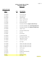
PAGE 12
PIZZAS OF EIGHT PIZZA SYSTEMS
OPERATOR'S MANUAL
MODEL PC18
PARTS LIST CONT.
PART #
QTY. DESCRIPTION
2A-200672 3 Shaft Collar
GF-100922 1 Drive Shaft PC18
GF-100923 1 Idler Shaft PC18
GB-112262 4 Shaft Bushings
2P-200643 1 25B11 x 5/16 Sprocket
2P-200654 1 25B24 x 3/8 Sprocket
SP-115360 3 Knob w/Cap & Skirt
2U-200590 1
Drive Motor 220V 50Hz Right to Left Belt Travel
2U-200504 1
Drive Motor 208-240V 60Hz Left to Right Belt Travel
2U-200509 1
Drive Motor 208-240V 60Hz Right to Left Belt Travel
GD-118060 1 Speed Control
2U-200561 1 Fan Motor 208-240V 60Hz
2R-200562 1 Fan Grill
2E-200566 1 Reset Switch
GF-160009 1 Conveyor Belt PC18
GF-100709 1 Belt Support System PC18
GG-101419 1 Right Side Tray PC18
GG-100419 1 Left Side Tray PC18
2E-200574 1 Fan Switch
GG-114250 9 Heater Tube, Metal, PC18, 208V
GG-114255 9 Heater Tube, Metal, PC18, 220V
2N-209207 9 Heater Tube, Metal, PC18, 240V
2J-200567 2 Heat Controls
2J-200568 2 Heat Probe
SP-115347 2 Stratford Control Assembly
GD-150023 1 Drive Chain
2E-200552 1 On/Off Rocker Switch
GG-416166 2 Heat Shutters
02/20/09 RB

PAGE 13
PIZZAS OF EIGHT PIZZA SYSTEMS
OPERATOR'S MANUAL
MODEL PC18
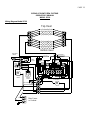
Wiring Diagram Model PC18
Temp. Probe
Temp. Probe
Bottom Heat
M
Cooling
Fan
Fan Control
Main Power
or Cordset
Top
Bottom
M
Pilot
Light
Conveyor
Motor Speed
Control
High Limit
Reset
Power
On / Off
L1
L2
Top Heat

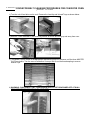
6-MONTH CONVEYOR BELT CLEANING PROCEDURES FOR CONVEYOR OVEN
MODEL 414HXM
1) Turn the unit off and allow unit to cool. Remove the Load Up and Unload Trays as shown below.
2) Remove Tunnel Extender by first removing screws as shown and lifting up and away from oven.
3) Turn Master On/Off Switch to the ON position and allow conveyor to advance until the three MASTER
CLIPS are visible. Turn the oven off and allow Conveyor Belt to cool before attempting to remove
Master Clips.
4) WARNING - DISCONNECT UNIT FROM POWER SUPPLY OR TURN POWER OFF AT WALL
BREAKER BEFORE PROCEDING TO NEXT STEP.

5) Remove Crumb Trays from load-up and unload end of oven.
6) Locate the three MASTER CLIPS in Conveyor Belt.
7) Begin at either side of the Conveyor Belt using a pair of Pliers and a flat tip Screwdriver. Remove the
first clip and repeat for remaining clips.
8) Once Master Clips have been removed, carefully open Conveyor Belt.
(NOTE: TO PREVENT DAMAGE TO ELEMENTS, DO NOT LET GO OF CONVEYOR BELT.)
MASTER

9) Pull upper section of Conveyor Belt through oven cavity.
10) Use a small wire brush or abrasive pad to clean metal rods and idler/drive shafts.
(NOTE: DO NOT ATTEMPT TO CLEAN HEATER TUBES.)
11) For heavily soiled Conveyor Belt, remove belt from oven and soak over night in hot soapy water. Pay
special attention to position of Conveyor Belt links for re-installation of the Conveyor Belt.
12) Clean interior of oven using a mild cleaner and damp cloth.
(NOTE: DO NOT SPRAY CLEANING SOLUTIONS INTO OVEN CAVITY.)
13) Reinstall Conveyor Belt by first lying belt along bottom of the oven cavity.
(NOTE: The smooth side of the belt must be installed to the outside
away from the sprockets.)
Next, pull one end of conveyor belt over the lower heater tubes and bring both ends of conveyor belt together.

14) Working from either side of Conveyor Belt, use Master Clips to connect both ends of Conveyor Belt
as shown below.
15) Repeat steps from pictures 1 through 4 for remainder of Master Clips.
16) Reinstall Tunnel Extender and Crumb Trays.
17) Reconnect oven to power supply and check for proper operation.
IF ASSISTANCE IS REQUIRED, CALL THE HOLMAN COOKING EQUIPMENT FACTORY SERVICE TEAM
AT 1-800-225-3958
1
2
3
4

STAR MANUFACTURING
10 Sunnen Drive, St. Louis, MO 63143 U.S.A.
(800) 807-9054 (314) 781-2777
Parts & Service (800) 807-9054
www.star-mfg.com
-
 1
1
-
 2
2
-
 3
3
-
 4
4
-
 5
5
-
 6
6
-
 7
7
-
 8
8
-
 9
9
-
 10
10
-
 11
11
-
 12
12
-
 13
13
-
 14
14
-
 15
15
-
 16
16
-
 17
17
-
 18
18
-
 19
19
-
 20
20


Holman PC18 Operating instructions
- Category
- Cookers
- Type
- Operating instructions
Ask a question and I''ll find the answer in the document
Finding information in a document is now easier with AI
Related papers
-
Star Manufacturing PC18 Operating instructions
-
 Holman 318HX Series Proveyor Multi Purpose Oven User manual
-
-
Star Manufacturing 214HX series Operating instructions
-
-
-
Holman QCS2 Operating instructions
-
-
 Holman EZ10 User manual


Other documents
-
Star UM1850AT Owner's manual
-
-
Bartscher 2002200 Operating instructions
-
-
 Holman Cooking/Star Mfg 314HXM Operating instructions
-
-
Star 210HX Owner's manual
-
 Holman Cooking/Star Mfg 314HXM Operating instructions
-
 Holman Cooking/Star Mfg 414HXM Operating instructions
-
 Holman Cooking/Star Mfg 318HX Operating instructions


