Page is loading ...

OPERATOR'S MANUAL
HOLMAN CONVEYOR OVENS
MODEL 314HXM
FOR SERVICE INFORMATION
U.S. AND CANADA CALL: 1-800-807-9054
24 HOURS/DAY 7 DAYS/WEEK
TABLE OF CONTENTS
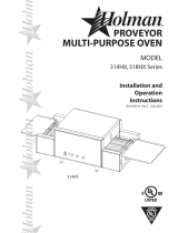
UNCRATING AND INSPECTION PAGE 1
ASSEMBLY AND INSTALLATION PAGE 1, 2, & 3
STACKING INSTRUCTIONS PAGE 3
OPERATION PAGE 4
CLEANING PROCEDURES PAGE 4
TROUBLESHOOTING GUIDE PAGE 5, 6, & 7,
MAINTENANCE PROCEDURES PAGE 8, 9, & 10
PARTS LIST/EXPLODED VIEW PAGE 11
DRAWINGS
ADJ. HEAT SHIELDS, FRONT VIEW PAGE 2
LOAD AND UNLOAD TRAYS PAGE 3 or 4
HEAT REFLECTOR/CRUMB TRAYS PAGE 6
DRIVE SYSTEM PAGE 7
HEATER TUBE & FAN MOTOR INSTALLATION PAGE 8
WIRING DIAGRAM SINGLE PHASE, 208/240 VOLT PAGE 12
WIRING DIAGRAM THREE PHASE, 208/240 VOLT PAGE 12a
Revised 12/23/2003
2M-HG0346
Electric Cooking Equipment for the Food Service Industry
Conveyor Toasters & Ovens Cheese Melters Broilers Pretzel Bakers
10 SUNNEN DRIVE, ST. Louis MO/U.S.A. 63143
Phone (314) 781-2777 FAX (314) 781-2714

PAGE 1
OPERATOR'S MANUAL
HOLMAN CONVEYOR OVENS
MODEL 314HXM
UNCRATING AND INSPECTION
Unpack unit and components from container. Remove all visible packing material, inspect unit for
damage. If damage is discovered, file a claim immediately with the carrier that handled the shipment.
The following should be included in the container:
A. 1ea. Conveyor oven with heaters and conveyor belt in place. Remove heating element shipping
supports.
B. 1ea. Stainless Steel Unload Tray and 1ea. Stainless Steel Load Up Tray.
ASSEMBLY AND INSTALLATION
A. Attach legs by screwing into weld nuts, as shown.
NOTE: LEGS MUST BE INSTALLED BEFORE OPERATING THIS UNIT!
B. Anti Skid pads are available at no charge and may be adhered to the foot section of each leg to
prevent sliding. Contact the Holman Cooking Equipment Factory Service Team at 1-800-807-9054 for
details.
CAUTION: Use of these pads is not approved by the National Sanitation Foundation.
C. Install unit in its operating position. The load & unload ends must be at least 6" from any vertical
combustible surfaces. Allow sufficient space for operating personnel.
1) Have an electrician connect input power to the unit in accordance with local electrical codes.
ASSEMBLY AND INSTALLATION CONT. ON PAGE 2
ADJUSTABLE LEGS SCREW INTO
WELD NUT ON BOTTOM OF UNIT.

PAGE 2
OPERATOR'S MANUAL
HOLMAN CONVEYOR OVENS
MODEL 314HXM
ASSEMBLY AND INSTALLATION (CONT)
WARNING:
MAKE SURE ALL INPUT POWER IS OFF BEFORE INSTALLING/REMOVING ANY PARTS.
WARNING:
BEFORE INSTALLING UNIT (S), CHECK WITH LOCAL POWER COMPANY TO DETERMINE
ACTUAL VOLTAGE AT JOB SITE. NEVER PLUG A 208 VOLT UNIT INTO 240 VOLTS OR A
240 VOLT UNIT INTO 208 VOLTS.
WARNING:
BE ABSOLUTELY SURE THE GROUND CONNECTION FOR THE RECEPTACLE IS
PROPERLY WIRED. NEVER CONNECT UNIT TO POWER WITHOUT PROPER GROUND
CONNECTIONS. IMPROPER GROUND MAY RESULT IN SEVERE INJURY OR FATALITY.
D. Before applying input power to the unit(s) check heating elements for breakage, do not apply power to
the unit(s) if a broken tube is found. If no broken tubes are found apply input power by switching the
master On/Off toggle to the ON position. Turn conveyor belt speed control to the maximum setting and
check all heater tubes and conveyor for proper operation.
E. Allow approximately 5 to 8 minutes for the fan cooling system to come on, check the air intake area as
noted below and be sure that there is a sufficient flow of air into the control box. (To ensure proper
airflow into the air intake area, the legs must be on the unit.)
F. If all heaters and conveyor system are operating properly, switch the master on/off switch to the OFF
position and allow unit to cool. The fan will continue to circulate cool air through out the unit until the
internal temperatures have been decreased.
G. If a problem is discovered during start up procedures, immediately switch the Master On/Off switch to
the OFF position and notify the Holman Cooking Equipment Factory Service Team at 1-800-807-
9054 (24 hours 7 days a week). Service will be arranged for you.
ASSEMBLY AND INSTALLATION CONT. ON PAGE 3
ADJUSTABLE HEAT SHUTTER
UPPER POSITION
LOWER POSITION
A
IR INTAKE LOCATED
ON BOTTOM CONTRO
L
BOX COVER.

PAGE 3
OPERATOR'S MANUAL
HOLMAN CONVEYOR OVENS
MODEL 314HXM
ASSEMBLY AND INSTALLATION (CONT.)
H. Install load and unload trays as shown.
I. Stacking Instructions
When stacking two Holman Proveyor ovens a stacking spacer with external air duct must
be used to
prevent overheating of the control box in the top oven.
1) If cart is to be used with units, place bottom unit on cart and align leg hole of unit to holes in top
portion of cart. Insert 3/8" bolts through cart and into leg holes to secure bottom unit to cart as
shown below.
2) Place stacking spacer on top of bottom oven with internal
air duct facing up and toward the rear of
the oven.
3) Mount external
air duct on stacking spacer as shown below. External air duct must be installed for
cooling system of top unit to function properly.
4) Install cap screws (4ea.) into leg holes on top oven.
5) Place top oven on stacking spacer. Cap screws will fit into cut outs in top of stacking spacer to lock
unit into position. (NOTE) Air intake of top unit must fit over the internal air duct of stacking
spacer to allow airflow into the control box of the top oven.
CRUMB TRA
Y
CRUMB TRA
Y
LOAD UP
TRAY
UNLOAD TRAY
MOUNTING BOLTS
FOR BOTTOM UNIT
SCREW INTO LEG
HOLES THROUGH
STACKING SPACER (REQUIRED)
MOUNTS ON TOP
OF BOTTOM OVEN
EXTERNAL AIR DUCT
MOUNTS ON SPACER
TOP UNIT- CAP SCREW
SCREWS INTO LEG HOLE
UNIT SITS ON TOP OF SPACER
BOTTOM UNIT - CAN
BE COUNTER MOUNTED OR
PLACED ON CART AS SHOWN

PAGE 4
OPERATOR'S MANUAL
HOLMAN CONVEYOR OVENS
MODEL 314HXM
OPERATION
A. Switch Master On/Off switch to the ON position and turn Variable Speed Control to fastest time setting.
B. Allow 10 to 15 minutes for unit(s) to warm up.
CLEANING PROCEDURES
Preventive maintenance for your Holman oven consists of the following recommended cleaning
procedures. To keep your oven in its top operating condition, these steps should be performed daily.
WARNING:
HIGH VOLTAGES ARE PRESENT IN THESE UNITS. BE SURE ALL INPUT POWER IS OFF
BEFORE SERVICING OR CLEANING UNIT.
A. Remove Load and Unload Trays (daily) as shown and wash with hot soapy water.
B. Remove the Crumb Trays from both load and unload ends of the oven (daily) as shown above,
(WASH WITH HOT SOAPY WATER ONLY).
C. For lightly soiled conveyor surfaces a damp cloth or scotch pad can be used without removing the
conveyor belt. (daily)
NOTE: For heavily soiled conveyor surfaces a STIFF WIRE brush may be used to clean
the conveyor belt.
NOTE:
LUBRICATION OF DRIVE CHAIN WITH A GRAPHITE BASED LUBRICANT IS REQUIRED AS
PERIODIC MAINTENANCE. CALL
THE HOLMAN COOKING EQUIPMENT FACTORY SERVICE TEAM AT 1-800-
807-9054
FOR DETAILS.
CRUMB TRAYCRUMB TRAY
LOAD UP
TRAY
UNLOAD TRAY

PAGE 5
OPERATOR'S MANUAL
HOLMAN CONVEYOR OVENS
MODEL 314HXM
TROUBLESHOOTING GUIDE
A. UNIT WILL NOT HEAT, CONVEYOR BELT WILL NOT TURN.
1) Be sure main Circuit Breaker is switched to the ON position and there is power at the outlet.
2) Check to see that the unit is connected to power and Master On/Off is switched to the ON position.
3) Be sure HEAT LIMIT SWITCH is pushed in (see below).
B. UNIT WILL NOT HEAT, CONVEYOR TURNS FREELY.
1) MAKE SURE AIR INTAKE ON BOTTOM OF UNIT IS FREE OF OBSTRUCTIONS.
2) Press Heat Limit Switch, located on the front section of the control box as shown above. If this
reactivates the Heater Tubes, see section C.
3) For further assistance call the Holman Cooking Equipment Factory Service Team at:
1-800-807-9054 (24 hours/day 7days a week).
TROUBLESHOOTING GUIDE CONT. ON PAGE 6
CUTAWAY VIEW OF CONTROL BOX WITHOUT
CONTROL BOX COVER.
HEAT LIMIT SWITCH LOCATED ON FRONT OF CONTROL BOX
BENEATH FRONT EXTENSION.

PAGE 6
OPERATOR'S MANUAL
HOLMAN CONVEYOR OVENS
MODEL 314HXM
TROUBLESHOOTING GUIDE CONT.
Your Holman Conveyor Oven is equipped with an automatically activated HEAT LIMIT SWITCH that interrupts
the heater tube connections if the air temperature in the control box exceeds 190F (88C). This Limit Switch can
be reset manually by pushing the button in the center of the switch, which is located as shown below.
C. HEAT LIMIT SWITCH
THE HEAT LIMIT SWITCH CAN BE ACTIVATED IF THERE IS NOT A PROPER AMOUNT OF AIR FLOW
BEING GENERATED BY THE COOLING FAN. IF THIS OCCURS:
1) DISCONNECT UNIT FROM POWER SOURCE.
2) Check to see if air intake area (openings in bottom center of Control Box) is free of dust, grease or
other obstructions.
3) Check to see if Crumb Trays (heat reflectors) are in place.
NEVER OPERATE UNIT WITHOUT CRUMB TRAYS IN POSITION AS THIS CAUSES OVERHEATING
IN THE CONTROL BOX.
TROUBLESHOOTING GUIDE CONT. ON PAGE 7
CRUMB TRAYCRUMB TRAY
HEAT LIMIT SWITCH

PAGE 7
OPERATOR'S MANUAL
HOLMAN CONVEYOR OVENS
MODEL 314HXM
TROUBLESHOOTING GUIDE CONT.
D. CONVEYOR WILL NOT TURN, UNIT HEATS PROPERLY.
1) DISCONNECT UNIT FROM POWER SOURCE.
2) Check to see if there are obstructions in the conveyor system that may cause a jam.
3) Remove Air Intake Cover as shown on page 9 and spin the Drive Motor Shaft as shown on page
10. Recheck to see if the Conveyor now works.
IF CONVEYOR STILL DOES NOT TURN:
4) Remove power cord side panel and Drive Motor Sprocket (see below). Manually move Conveyor Belt to
check for mechanical binding. If Conveyor moves freely, contact the Holman Cooking Equipment Factory
Service Team at 1-800-807-9054 as Drive Motor and/or Variable Speed Control may have to be replaced
(refer to page 10 for instructions on replacing drive motor).
E. CONVEYOR TURNS AT ONE SPEED REGARDLESS OF SPEED CONTROL SETTING.
1) Call the Holman Cooking Equipment Factory Service Team at 1-800-807-9054 as Variable Speed
Control may have to be replaced.
F. COOLING FAN DOES NOT START.
1) DISCONNECT UNIT FROM POWER SOURCE.
2) Remove Control Box Cover and check Fan Blade for obstructions.
3) Check Fan Motor Cord for secure connection.
4) Call the Holman Cooking Equipment Factory Service Team at 1-800-807-9054 as the Fan
Switch and/or Fan Motor may have to be replaced.
DRIVE CHAIN
DRIVE SPROCKET
DRIVEN SPROCKET
FAN MOTOR
SECURED BY 4 SCREWS
AIR INTAKE
CONTROL BOX COVER

PAGE 8
OPERATOR'S MANUAL
HOLMAN CONVEYOR OVENS
MODEL 314HXM
MAINTENANCE PROCEDURES
A. REPLACING HEATER TUBES (see below)
1) DISCONNECT UNIT FROM POWER SOURCE.
2) Remove left and right side panels by removing the truss head screws in each panel. Pull the top of
each panel out slightly and lift up.
3) Disconnect heater tube wires, which require replacement from terminal block connections.
4) Remove Heater Tube Retainer by removing retainer screw with washer (retainers are located on
power supply side of unit).
5) GENTLY, pull defective Heater Tube out of unit.
6) GENTLY, place new Heater Tube into unit.
7) Replace heater tube retainers.
8) Reconnect heater wires to terminal block connections.
9) Replace side panels and test unit for proper operation. Call the Holman Cooking Equipment
Factory Service Team at 1-800-807-9054 assistance is required.
B. REPLACING FAN MOTOR
1) DISCONNECT UNIT FROM POWER SOURCE.
2) Remove control box cover with Fan Motor.
3) Unplug power supply cord from Fan Motor.
4) Remove (4) screws that hold Fan Motor and grill to cover.
5) On the side of the fan motor there are two arrows. One facing down (air flow) and the other facing
the side (fan direction) (see below Fig. A) Attach the replacement motor to the control box cover
with the up and down arrow pointed towards the internal controls. The label on the motor should
also face towards the internal controls and the side arrow should be pointed left. Secure the motor
and grill to the control box cover with the screws.
6) Reconnect power supply cord to Fan Motor.
7) Replace control box cover.
MAINTENANCE PROCEDURES CONT. ON PAGE 9
HEATER
TUBE RETAINERS
HEATER TUBE
SIDE PANEL
FAN MOTOR
SECURED BY 4 SCREWS
AIR INTAKE
CONTROL BOX COVER
B
C
A
A
rrows on the side of Fan Moto
r
Fan
Direction
Air Flow

PAGE 9
OPERATOR'S MANUAL
HOLMAN CONVEYOR OVENS
MODEL 314HXM
MAINTENANCE PROCEDURES CONT.
C. REPLACING BELT DRIVE MOTOR
1) DISCONNECT UNIT FROM POWER SOURCE.
2) Remove power cord side panel and control box cover.
3) Remove sprocket from motor shaft by loosening the allen screw on the sprocket.
4) Disconnect the leads from the Drive Motor to the internal wiring. Motors are rated 208 Volts or 240
Volts. N
OTE WHICH COLOR LEADS ARE BEING USED FOR THESE CONNECTIONS AND WHICH LEAD IS
CAPPED WITH WHITE TAPE
. THE NEW DRIVE MOTOR SHOULD USE THE SAME ARRANGEMENT.
5) Remove the four screws that hold the Drive Motor in place.
6) Put the new motor in place and loosely attach with the four screws removed from step 5.
7) Replace the Sprocket onto the motor shaft, then replace the Drive Chain onto the sprockets.
8) Slide the Drive Motor until the Drive Chain has about 1/8" slack when lightly pushed at the center
of its top open run. Align drive and driven sprockets evenly before tightening to prevent binding.
Tighten the Drive Motor screws.
9) Rewire the Drive Motor as described in step 4 above. Replace the panels and test for proper
operation.
MAINTENANCE PROCEDURES CONT. ON PAGE 10
DRIVE SPROCKET WITH SET SCREW
DRIVE MOTOR
DRIVE MOTOR
MOUNTING SCREW
CUT AWAY VIEW OF DRIVE MOTOR
IN CONTROL BOX.

PAGE 10
OPERATOR'S MANUAL
HOLMAN CONVEYOR OVENS
MODEL 314HXM
MAINTENANCE PROCEDURES CONT.
D. REPLACING THE VARIABLE SPEED CONTROL (see below)
1) DISCONNECT UNIT FROM POWER SOURCE.
2) Turn unit over and lay on top cover with the legs pointing at the ceiling.
3) Remove Phillips head screws holding control box cover in place. Lift and slide forward to remove
cover.
4) Locate the motor controller mounted in the top center of the control box.
5) Wires from Variable Speed Control go in to terminals located on the controller. Note the location
of the colored leads and remove wires for Variable Speed Control.
6) Disconnect the wires from terminals marked L, N, M1 and M2 (note which wires go to each
terminal).
7) Remove Phillips head screws (4ea.) holding controller in place.
8) Mount replacement control in the same manner as the old control.
9) Reconnect wires removed from old control (refer to diagram on page 13 for wire locations).
10) Replace control box cover, place unit on legs and connect to power supply. Test for proper
operation.
11) Call the Holman Factory Service Team at 800-807-9054 if assistance is required.
M1 M2
W
Y
B
L
N
SPEED
CONTROL

PAGE 11
OPERATOR'S MANUAL
HOLMAN CONVEYOR OVENS
MODEL 314HXM
PARTS LIST
No. PART No. DESCRIPTION Qty No. PART No. DESCRIPTION Qty
1 GD-401168 Cover, Top 1 16 GB-118062 Speed control 1
GD-197991 Heater Tube, Top, 208V 4 17 2E-200566 Reset Switch 1
2
GE-197988 Heater tube, Bottom 208V 5 18 2U-200561 Fan Motor 1
GE-197992 Heater Tube, Top, 240V 4 19 GD-401636 Cover, Control Box 1
2a.
GE-197990 Heater Tube, Bottom 240V 5 20 2R-200562 Grill, Fan Motor 1
3 GD-401232 Retainer, Heater Tube 5 21 GD-100403 Load Up Tray 1
4 GD-160008 Conveyor Belt 1 22 GD-101403 Unload Tray 1
5 GD-100707 Belt Support Rack 1 23 GD-416764 Side Panel 1
6 GD-101251 Idler Shafts 1 24 GD-401376 Side Panel, Cord 1
7 GD-101252 Drive Shaft 1 25 2R-200716 Leg, Metal, 2" 4
8 GB-112262 Bearing 4 26 GD-401233 Shutter, Heat 2
9 2U-200504 Drive Motor 1 27 GD-416162 Panel, Controls 1
10 GD-150023 Drive Chain 1 28 GD-401227 Crumb Tray 2
11 2P-200652 Driven Sprocket 3/8” 1 2E-Z8966 Contactor 50 AMP 208/240V, HXM 1
12 2P-200646 Drive sprocket 5/16” 1
29
PS-Z14660 Contactor 40 AMP 208/240V, HXMA 1
13 2E-200574 Fan Switch 1 30 SP-115360 Knob, Speed control 1
14 2E-200552 On/Off Switch/Rocker Swt 1 31 GD-401206 Cover, Extensions 3
15 2J-200427 Pilot Light 1 2U-200579 Motor Controller (not shown) 1
1.
2.
3.
4.
5.
6.
7.
8.
8.
8.
8.
9.
10.
11.
12.
13.
17.
18.
19.
20.
22.
23.
25.
26.
24.
27.
21.
28.
28.
14.
15.
16.
29.
31.
30.

PAGE 12
OPERATOR'S MANUAL
HOLMAN CONVEYOR OVENS
MODEL 314HXM
WIRE DIAGRAM FOR MODEL 314HXM
L2
L1
T1
L1
T2
L2
T3 L3
M1 M2
W
Y
B
L
N
TOP HEATER TUBES
BOTTOM HEATER TUBES
SPEED
CONTROL
ON/OFF
SWITCH
PILOT
LIGHT
CONTACTOR
LIMIT
SWITCH
FAN MOTOR
FAN SWITCH
DRIVE MOTOR
GROUND

PAGE 12a
OPERATOR'S MANUAL
HOLMAN CONVEYOR OVENS
MODEL 314HXM
WIRE DIAGRAM MODEL 314HXM THREE (3) PHASE
M1 M2
L
N
L1
L2
L3
G
WHITE
WHITE
WHITE
WHITE
FRONT HEAT
TOP HEAT
BOTTOM HEAT
WHITE
WHITE
WHITE
WHITE
WHITE
FAN MOTOR
FAN
SWITCH
HIGH LIMIT
RESET
PILOT
LIGHT
ON
/
OFF
SWITCH
DRIVE MOTOR
SPEED
CONTROL
CONTROLLE
R
T1 L1
T2 L2
T3 L3


STAR INTERNATIONAL HOLDINGS INC. COMPANY
Star - Holman - Lang - Wells - Bloomeld - Toastmaster
10 Sunnen Drive, St. Louis, MO 63143 U.S.A.
(314) 781-2777
www.star-mfg.com
/