Page is loading ...
January
1985
FORM:
OM-1085B
OWN
ERS
MANUAL
MODEL
WELD
OSCILLATOR
flLE
COPY
RETURN
TO
FOLDER
MILLER
ELECTRIC
MFG.
CO.
718
S.
BOUNDS
ST,
P.O.
Box
1079
APPLETON,
WI
54912
USA
ADDITIONAL
COPY
PRICE
75
CENTS
NWSA
CODE
NO.
4579
PRINTED
IN
U.S.A.
I.
Effective
With
Serial
No.
JF850281

i~:~
L~
~..&P
~
L~
~
LIMITED
WARRANTY
EFFECTIVE:
JUNE
1,
1979
This
warranty
supersedes
all
previous
MILLER
warranties
and
is
ex
clusive
with
no
other
guarantees
or
warranties
expressed
or
implied.
LIMITED
WARRANTY-Subject
to
the
terms
and
conditions
As
a
matter
of
general
policy
only,
Miller
may
honor
claims
hereof,
Miller Electric
Mfg.
Co..
Appleton,
Wisconsin
warrants
submitted
by
the
original
user
within
the
foregoing
periods.
to
its
Distributor/Dealer
that
all
new
and unused
Equipment
(~
furnished
by
Miller
is
free
from
defect
in
workmanship
and
In
the
case
of
Millers
breach
of
warranty
or
any
other
duty
~
material
as
of
the
time
and
place
of
delivery
by
Miller.
No
war-
with
respect
to
the
quality
of
any
goods,
the
exclusive
remedies
ranty
is
made
by
Miller
with
respect
to
engines,
trade
ac-
therefore
shall
be,
at
Millers
option
Ii)
repair
or
121
replacement
cessories
or
other
items
manufactured
by
others.
Such
or,
where
authorized
in
writing
by
Miller
in
appropriate
cases,
(3)
engines,
trade
accessories
and
other
items
are
sold
subject
to
the
reasonable
cost
of
repair
or
replacement
at
an
authorized
the
warranties
of
their
respective
manufacturers,
if
any
.
All
Miller
service
station
or
141
payment
of
or
credit
for
the
purchase
engines
are
warranted
by
their
manufacturer
for
one
year
from
price
Iless
reasonable
depreciation
based
upon
actual
usel
upon
date
of
original
purchase.
return
of
the
goods
at
Customers
risk
and
expense.
Upon
receipt
of
notice
of
apparent
defect
or
failure,
Miller
shall
instruct
the
clai-
?
Except
as
specified
below,
Millers
warranty
does
not
apply
mant
on
the
warranty
claim
procedures
to
be
followed.
to
components
having
normal
useful
life
of
less
than
one
(1)
year,
such
as
spot
welder
tips,
relay
and
contactor
points,
ANY
EXPRESS
WARRANTY
NOT
PROVIDED
HEREIN
AND
MILLERMATIC
parts
that
come
in
contact
with
the
welding
ANY
IMPLIED
WARRANTY,
GUARANTY
OR
REPRESENTA-
wire
including
nozzles
and
nozzle
insulators
where
failure
does
lION
AS
TO
PERFORMANCE,
AND
ANY
REMEDY
FOR
not
result
from
defect
in
workmanship
or
material.
BREACH
OF
CONTRACT
WHICH,
BUT
FOR
THIS
PROVISION,
k~
MIGHT
ARISE
BY
IMPLICATION,
OPERATION
OF
LAW,
Miller
shall
be
required
to
honor
warranty
claims
on
war-
CUSTOM
OF
TRADE
OR
COURSE
OF
DEALING,
INCLUDING
ranted
Equipment
in
the
event
of
failure
resulting
from
a
defect
ANY
IMPLIED
WARRANTY
OF
MERCHANTABILITY
OR
OF
within
the
following
periods
from
the
date
of
delivery
of
Equip-
FITNESS
FOR
PARTICULAR
PURPOSE,
WITH
RESPECT
TO
(
ment
to
the
original
user:
ANY
AND
ALL
EQUIPMENT
FURNISHED
BY
MILLER
IS
EX
CLUDED
AND
DISCLAIMED
BY
MILLER.
1.
Arc
welders,
power
sources
and
components
.
1
year
2.
Original
main
power
rectifiers
3
years
EXCEPT
AS
EXPRESSLY
PROVIDED
BY
MILLER
IN
Ilabor
-
1
year
onlyl
WRITING,
MILLER
PRODUCTS
ARE
INTENDED
FOR
3.
All
welding
guns
and
feeder/guns
90
days
ULTIMATE
PURCHASE
BY
COMMERCIAL/INDUSTRIAL
4.
All
other
Millermatic
Feeders
1
year
USERS
AND
FOR
OPERATION
BY
PERSONS
TRAINED
AND
5.
Replacement
or
repair
parts,
exclusive
of
labor
60
days
EXPERIENCED
IN
THE
USE
AND
MAINTENANCE
OF
6.
Batteries
6
months
WELDING
EQUIPMENT
AND
NOT
FOR
CONSUMERS
OR
~s
CONSUMER
USE.
MILLER
WARRANTIES
DO
NOT
EXTEND
provided
that
Miller
is
notified
in
writing
within
thirty
130)
days
TO,
AND
NO
RESELLER
IS
AUTHORIZED
TO
EXTEND
of
the
date
of
such
failure.
MILLERS
WARRANTIES
TO,
ANY
CONSUMER.
~t,
~r
:%...,~,
j~
t.
~
July
12,
1985
FORM:
OM-1085B
ERRATA
SHEET
After
this
manual
was
printed,
refinements
in
equipment
design
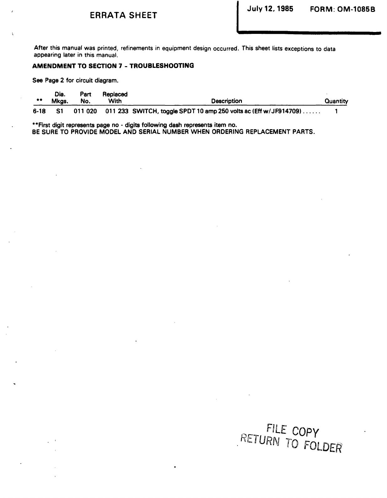
occurred.
This
sheet
lists
exceptions
to
data
appearing
later
in
this
manual.
AMENDMENT
TO
SECTION
7
-
TROUBLESHOOTING
See
Page
2
for
circuit
diagram.
Dia.
Part
Replaced
~
Mkgs.
No.
With
Description
Quantity
6-18
Si
011
020
011
233
SWITCH,
toggle
SPDT
10
amp25O
voitsac
(Eff
w/JF914709)
1
~Fji~st
digit
represents
page
no
-
digits
following
dash
represents
item
no.
BE
SURE
TO
PROVIDE
MODEL
AND
SERIAL
NUMBER
WHEN
ORDERING
REPLACEMENT
PARTS.
FILE
Copy
RLTURN
TO
FOLDER
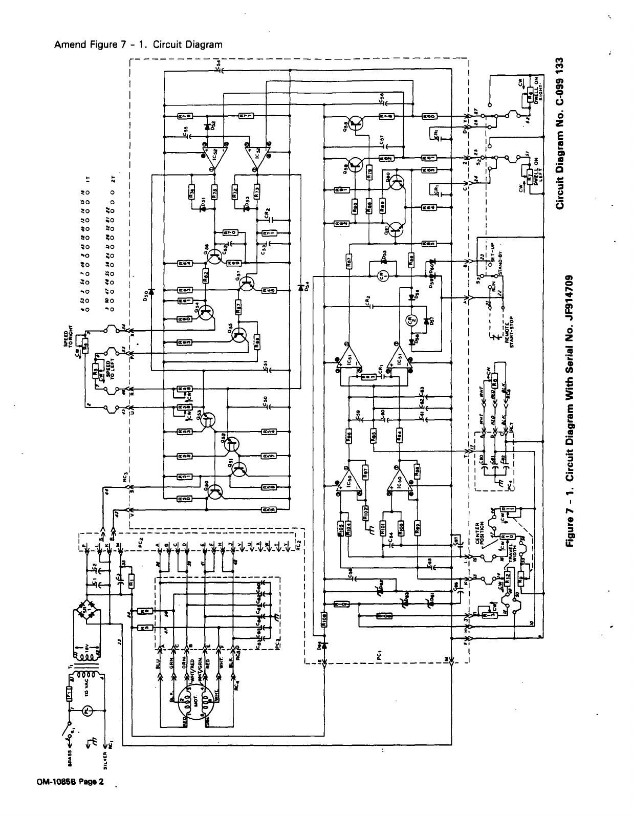
Amend
Figure
7
-
1.
Circuit
Diagram
I-
~o
0
~o
0
~o
~o
~o
~o
~o
~o
~o
~0
~o
~o
.o
~o
~o
~o
~0
~O
~o
~o
-o
~o
~o
~o
~0
0
C,,
C,
a,
0,
a
E
0
C)
-~---
f~I
~-
~-~e.--4
-~1E--
~
_
0
a
0
U~
f-~-
-
ul
I
____________
I
I
1
I
I
I~0
44-j~
I~
t
~
Ht
II
I
:
~I1_
-~-4
L~!~J
-1~~-
~
alE
a,
0
r.
tt
tt
~1kL-
--
-J
uI(
j
I
~t
.~iT
I
r
~:
i
U
a
-
;-
~
~
OM-10868
Page
2
~Jf.i.J
~._~7__~!
I
-
I
g
L~
~-JI
.,
L--~
z
~
0
~.
-~
-
.~
-
~-
J~
3
~I
P
II
T
%-
m
L~
~
V
~
U
0.
I

TABLE
OF
CONTENTS
Section
No.
Page
No.
SECTION
1
-
SAFETY
RULES
FOR
OPERATION
OF
ARC
WELDING
POWER
SOURCE
1
-
1.
Introduction
1
1
-
2.
General
Precautions
1
1
-3.
Arc
Welding
4
1
-
4.
Standards
Booklet
Index
6
SECTION
2
-
INTRODUCTION
2-1.
General
7
2
-
2.
Receiving-Handling
7
2
-
3.
Description
7
2-4.
Safety..~
7
SECTION
3
-
INSTALLATION
3-1.
Location
7
3
-
2.
Interconnecting
Cable
Installation
7
3
-
3.
Control
Cable
Installation
8
3
-
4.
Power
Cord
Installation
8
3
-
5.
Remote
Control
Installation
8
3
-
6.
Remote
Start-Stop
Switch
Installation
8
3
-
7.
Remote
Dwell
On
Left
Control
Installation
9
3
-
8.
Remote
Dwell
On
Right
Control
Installation
9
3
-
9.
Remote
Travel
Width
Control
Installation
9
3-10.
Remote
Center
Position
Control
Installation
9
3-11.
Remote
Speed
To
Left
Control
Installation
9
3-12.
Remote
Speed
To
Right
Control
Installation
9
SECTION
4
-
OPERATOR
CONTROLS
4
-
1.
Power
Switch
10
4
-
2.
Pilot
Light
10
4
-
3.
Condition
Switch
10
4-4.
DwellControls
10
4
-
5.
Speed
Controls
10
4
-
6.
Travel
Width
10
4
-
7.
Center
Position
11
4
-
8.
Travel
Width
And
Center
Position
Internal
Adjustments
11
SECTION
5
-
SEQUENCE
OF
OPERATION
5
1.
Initial
Adjustments
11
5
-
2.
Shutting
Down
12
SECTION
6
-
MAINTENANCE
6-1.
Control
12
6
-
2.
Drive
Motor
12
6-3.
Slide
12
6
-
4.
Drive
Belt
12
6
-
5.
Slide
Potentiometer
12
SECTION
7
-
TROUBLESHOOTING

SECTION
1
-
SAFETY
RULES
FOR
OPERATION
OF
ARC
WELDING
POWER
SOURCE~
1-1.
INTRODUCTION
-
We
learn
by
experience.
Learning
safety
through
personal
experience,
like
a
child
touching
a
hot
stove
is
harmful,
wasteful,
and
un
wise.
Let
the
experience
of
others
teach
you.
Safe
practices
developed
from
experience
in
the
use
of
welding
and
cutting
are
described
in
this
manual.
Research,
development,
and
field
experience
have
evolved
reliable
equipment
and
safe
installation,
opera
tion,
and
servicing
practices.
Accidents
occur
when
equipment
is
improperly
used
or
maintained.
The
reason
for
the
safe
practices
may
not
always
be
given.
Some
are
based
on
common
sense,
others
may
require
technical
volumes
to
explain.
It
is
wiser
to
follow
the
rules.
Read
and
understand
these
safe
practices
before
at
tempting
to
install,
operate,
or
service
the
equipment.
Comply
with
these
procedures
as
applicable
to
the
par
ticular
equipment
used
and
their
instruction
manuals,
for
personal
safety
and
for
the
safety
of
others.
Failure
to
observe
these
safe
practices
may
cause
serious
injury
or
death.
When
safety
becomes
a
habit,
the
equipment
can
be
used
with
confidence.
These
safe
practices
are
divided
into
two
Sections:
1
-
General
Precautions,
common
to
arc
welding
and
cutting;
and
2
-
Arc
Welding
(and
Cutting)
(only).
Reference
standards:
Published
Standards
on
safety
are
also
available
for
additional
and
more
complete
pro
cedures
than
those
given
in
this
manual.
They
are
listed
in
the
Standards
Index
in
this
manual.
ANSI
Z49.1
is
the
most
complete.
The
National
ElectricalCode,
Occupational
Safety
and
Health
Administration,
local
industrial
codes,
and
local
inspection
requirements
also
provide
a
basis
for
equip
ment
installation,
use,
and
service.
1-2.
GENERAL
PRECAUTIONS
Different
arc
welding
processes,
electrode
alloys,
and
fluxes
can
produce
different
fumes,
gases,
and
radiation
levels.
In
addition
to
the
information
in
this
manual,
be
sure
to
consult
flux
and
elec
trode
manufacturers
for
specific
technical
data
and
precautionary
measures
concerning
their
material.
A.
Burn
Prevention
Wear
protective
clothing
-
gauntlet
gloves
designed
for
use
in
welding,
hat,
and
high
safety-toe
shoes.
Button
shirt
collar
and
pocket
flaps,
and
wear
cuffless
trousers
to
avoid
entry
of
sparks
and
slag.
Wear
helmet
with
safety
goggles
or
glasses
with
side
shields
underneath,
appropriate
filter
lenses
or
plates
(protebted
by
clear
cover
glass).
This
is
a
MUST
for
welding
or
cutting,
(and
chipping)
to
protect
the
eyes
from
radiant
energy
and
flying
metal.
Replace
cover
glass
when
broken,
pitted,
or
spattered.
See
1-3A.2.
Avoid
oily
or
greasy
clothing.
A
spark
may
ignite
them.
Hot
metal
such
as
electrode
stubs
and
workpieces
should
never
be
handled
without
gloves.
Medical
first
aid
and
eye
treatment.
First
aid
facilities
and
a
qualified
first
aid
person
should
be
available
for
each
shift
unless
medical
facilities
are
close
by
for,
im
mediate
treatment
of
flash
burns
of
the
eyes
and
skin
burns.
Ear
plugs
should
be
worn
when
working
on
overhead
or
in
a
confined
space.
A
hard
hat
should
be
worn
when
others
work
overhead.
Flammable
hair
preparations
should
not
be
used
by
per
sons
intending
to
weld
or
cut.
B.
Toxic
Fume
Prevention
Severe
discomfort,
illness
or
death
can
result
from
fumes,
vapors,
heat,
or
oxygen
enrichment
or
depletion
that
welding
(or
cutting)
may
produce.
Prevent
them
with
adequate
ventilation
as
described
in
ANSI
Stan
dard
Z49.1
listed
1
in
Standards
index.
NEVER
ventilate
with
oxygen.
Lead
-,
cadmium
-,
zinc
-,
mercury
-,
and
beryllium
-
bearing
and
similar
materials,
when
welded
(or
cut)
may
produce
harmful
concentrations
of
toxic
fumes.
Ade
quate
local
exhaust
ventilation
must
be
used,
or
each
person
in
the
area
as
well
as
the
operator
must
wear
an
air-supplied
respirator.
For
beryllium,
both
must
be
us
ed.
Metals
coated
with
or
containing
materials
that
emit
toxic
fumes
should
not
be
heated
unless
coating
is
removed
from
the
work
surface,
the
area
is
well
ven
tilated,
or
the
operator
wears
an
air-supplied
respirator.
Work
in
a
confined
space
only
while
it
is
being
ven
tilated
and,
if
necessary,
while
wearing
an
air-supplied
respirator.
Gas
leaks
in
a
confined
space
should
be
avoided.
Leaked
gas
in
large
quantities
can
change
oxygen
con
centration
dangerously.
Do
not
bring
gas
cylinders
into
a
confined
space.
Leaving
confined
space,
shut
OFF
gas
supply
at
source
to
prevent
possible
accumulation
of
gases
in
the
space
if
downstream
valves
have
been
accidently
opened
or
left
open.
Check
to
be
sure
that
the
space
is
safe
before
re-entering
it.
Vapors
from
chlorinated
solvents
can
be
decomposed
by
the
heat
of
the
arc
(or
flame)
to
form
PHOSGENE,
a
OM-1085
Page
1

highly
toxic
gas,
and
other
lung
and
eye
irritating
pro
ducts.
The
ultraviolet
(radiant)
energy
ofthe
arc
can
also
decompose
trichioroethylene
and
per
chloroethylene
vapors
to
form
phosgene.
DO
NOT
WELD
or
cut
where
solvent
vapors
can
be
drawn
into
the
welding
or
cutting
atmosphere
or
where
the
radiant
energy
can
penetrate
to
atmospheres
containing
even
minute
amounts
of
trichloroethylene
or
per
chloroethylene.
C.
Fire
and
Explosion
Prevention
Causes
of
fire
and
explosion
are:
combustibles
reached
by
the
arc,
flame,
flying
sparks,
hot
slag
or
heated
material;
misuse
of
compressed
gases
and
cylinders;
and
short
circuits.
BE
AWARE
THAT
flying
sparks
or
falling
slag
can
pass
through
cracks,
along
pipes,
through
windows
or
doors,
and
through
wall
or
floor
openings,
out
of
sight
of
the
goggled
operator.
Sparks
and
slag
can
fly
35
feet.
To
prevent
fires
and
explosion:
Keep
equipment
clean
and
operable,
free
of
oil,
grease,
and
(in
electrical
parts)
of metallic
particles
that
can
cause
short
circuits.
If
combustibles
are
in
area,
do
NOT
weld
or
cut.
Move
the
work
if
practicable,
to
an
area
free
of
combustibles.
Avoid
paint
spray
rooms,
dip
tanks,
storage
areas,
yen
tilators.
If
the
work
cannot
be
moved,
move
com
bustibles
at
least
35
feet
away
out
of
reach
of
sparks
and
heat;
or
protect
against
ignition
with
suitable
and
snug-fitting,
fire-resistant
covers
or
shields.
Walls
touching
combustibles
on
opposite
sides
should
not
be
welded
on
(or
cut).
Walls,
ceilings,
and
floor
near
work
should
be
protected
by
heat-resistant
covers
or
shields.
Fire
watcher
must
be
standing
by
with
suitable
fire
ex
tinguishing
equipment
during
and
for
some
time
after
welding
or
cutting
if:
a.
appreciable
combustibles
(including
building
construction)
are
within
35
feet
b.
appreciable
combustibles
are
further
than
35
feet
but
can
be
ignited
by
sparks
c.
openings
(concealed
or
visible)
in
floors
or
walls
within
35
feet
may
expose
com
bustibles
to
sparks
d.
combustibles
adjacent
to
walls,
ceilings,
roofs,
or
metal
partitions
can
be
ignited
by
radiant
or
conducted
heat.
Hot
work
permit
should
be
obtained
before
operation
to
ensure
supervisors
approval
that
adequate
precautions
have
been
taken.
After
work
is
done,
check
that
area
is
free
of
sparks,
glowing
embers,
and
flames.
An
empty
container
that
held
combustibles,
or
that
can
produce
flammable
or
toxic
vapors
when
heated,
must
never
be
welded
on
or
cut,
unless
container
has
first
been
cleaned
as
described
in
AWS
Standard
A6.O,
listed
3
in
Standards
index.
This
includes:
a
thorough
steam
or
caustic
cleaning
(or
a
solvent
or
water
washing,
depending
on
the
com
bustibles
solubility)
followed
by
purging
and
inerting
with
nitrogen
or
carbon
dioxide,
and
using
protective
equipment
as
recommended
in
A6.O.
Waterfilling
just
below
working
level
may
substitute
for
inerting.
A
container
with
unknown
contents
should
be
cleaned
(see
paragraph
above).
Do
NOT
depend
on
sense
of
smell
or
sight
to
determine
if
it
is
safe
to
weld
or
cut.
Hollow
castings
or
containers
must
be
vented
before
welding
or
cutting.
They
can
explode.
Explosive
atmospheres.
Never
weld
or
cut
where
the
air
may
contain
flammable
dust,
gas,
or
liquid
vapors
(such
as
gasoline).
D.
Compressed
Gas
Equipment
Standard
precautions.
Comply
with
precautions
in
this
manual,
and
those
detailed
in
CGA
Standard
P-i,
PRECAUTIONS
FOR
SAFE
HANDLING
OF
COMPRESSED
GASES
IN
CYLINDERS,
listed
6
in
Standards
index.
1.
Pressure
Regulators
Regulator
relief
valve
is
designed
to
protect
only
the
regulator
from
overpressure;
it
is
not
intended
to
protect
any
downstream
equipment.
Provide
such
protection
with
one
or
more
relief
devices.
Never
connect
a
regulator
to
a
cylinder
containing
gas
other
than
that
for
which
the
regulator
was
designed.
Remove
faulty
regulator
from
service
immediately
for
repair
(first
close
cylinder
valve).
The
following
symptoms
indicate
a
faulty
regulator:
Leaks
-
if
gas
leaks
externally.
Excessive
Creep
-
if
delivery
pressure
continues
to
rise
with
downstream
valve
closed.
Faulty
Gauge
-
if
gauge
pointer
does
not
move
off
stop
pin
when
pressurized,
nor
returns
to
stop
pin
after
pressure
release.
Repair.
Do
NOT
attempt
repair.
Send
faulty
regulators
for
repair
to
manufacturers
designated
repair
center,
where
special
techniques
and
tools
are
used
b~
trained
personnel.
2.
Cylinders
Cylinders
must
be
handled
carefully
to
prevent
leaks
and
damage
to
their
walls,
valves,
or
safety
devices:
Avoid
electrical
circuit
contact
with
cylinders
in
cluding
third
rails,
electrical
wires,
or
welding
cir
cuits.
They
can
produce
short
circuit
arcs
that
may
lead
to
a
serious
accident.
(See
i-3C.)
OM-1085
Page
2
ICC
or
DOT
marking
must
be
on
each
cylinder.
It
is
an
assurance
of
safety
when
the
cylinder
is
properly
handled.
Identifying
gas
content.
Use
only
cylinders
with
name
of
gas
marked
on
them;
do
not
rely
on
color
to
identify
gas
content.
Notify
supplier
if
unmarked.
NEVER
DEFACE
or
alter
name,
number,
or
other
markings
on
a
cylinder.
It
is
illegal
and
hazardous.
Empties:
Keep
valves
closed,
replace
caps
securely;
mark
MT;
keep
them
separate
from
FULLS
and
return
promptly.
Prohibited
use.
Never
use
a
cylinder
or
its
contents
for
other
than
its
intended
use,
NEVER
as
a
support
or
roller.
Locate
or
secure
cylinders
so
they
cannot
be
knocked
over.
Passageways
and
work
areas.
Keep
cylinders
clear
of
areas
where
they
may
be
struck.
Transporting
cylinders.
With
a
crane,
use
a
secure
sup
port
such
as
a
platform
or
cradle.
Do
NOT
lift
cylinders
off
the
ground
by
their
valves
or
caps,
or
by
chains,
slings,
or
magnets.
Do
NOT
expose
cylinders
to
excessive
heat,
sparks,
slag,
and
flame,
etc.
that
may
cause
rupture.
Do
not
allow
contents
to
exceed
130F.
tool
with
water
spray
where
such
exposure
exists.
Protect
cylinders
particularly
valves
from
bumps,
falls,
falling
objects,
and
weather.
Replace
caps
securely
when
moving
cylinders.
Stuck
valve.
Do
NOT
use
a
hammer
or
wrench
to
open
a
cylinder
valve
that
can
not
be
opened
by
hand.
Notify
your
supplier.
Mixing
gases.
Never
try
to
mix
any
gases
in
a
cylinder.
Never
refill
any
cylinder.
Cylinder
fittings
should
never
be
modified
or
exchang
ed.
Coil
excess
hose
to
prevent
kinks
and
tangles.
Protect
hose
from
damage
by
sharp
edges,
and
by
sparks,
slag,
and
open
flame.
Examine
hose
regularly
for
leaks,
wear,
and
loose
con
nections.
Immerse
pressured
hose
in
water;
bubbles
in
dicate
leaks.
Repair
leaky
or
worn
hose
by
cutting
area
out
and
splic
ing
(1-2D3).
Do
NOT
use
tape.
4.
Proper
Connections
Clean
cylinder
valve
outlet
of
impurities
that
may
clog
orifices
and
damage
seats
before
connecting
regulator.
Except
for
hydrogen,
crack
valve
momentarily,
pointing
outlet
away
from
people
and
sources
of
ignition.
Wipe
with
a
lean
lintless
cloth.
Match
regulator
to
cylinder.
Before
connecting,
check
that
the
regulator
label
and
cylinder
marking
agree,
and
that
the
regulator
inlet
and
cylinder
outlet
match.
NEVER
CONNECT
a
regulator
designed
for
a
particular
gas
or
gases
to
a
cylinder
containing
any
other
gas.
Tighten
connections.
When
assembling
threaded
con
nections,
clean
and
smooth
seats
where
necessary.
Tighten.
If
connection
leaks,
disassemble,
clean,
and
retighten
using
properly
fitting
wrench.
Adapters.
Use
a
CGA
adapter
(available
from
your
sup
plier)
between
cylinder
and
regulator,
if
one
is
required.
Use
two
wrenches
to
tighten
adapter
marked
RIGHT
and
LEFT
HAND
threads.
Regulator
outlet
(or
hose)
connections
may
be
iden
tified
by
right
hand
threads
for
oxygen
and
left
hand
threads
(with
grooved
hex
on
nut
or
shank)
for
fuel
gas.
5.
Pressurizing
Steps:
Drain
regulator
of
residual
gas
through
suitable
vent
before
opening
cylinder
(or
manifold
valve)
by
turning
adjusting
screw
in
(clockwise).
Draining
prevents
ex
cessive
compression
heat
at
high
pressure
seat
by
allowing
seat
to
open
on
pressurization.
Leave
adjusting
screw
engaged
slightly
on
single-stage
regulators.
3.
Hose
Stand
to
side
of
regulator
while
opening
cylinder
valve.
Prohibited
use.
Never
use
hose
other
than
that
designed
for
the
specified
gas.
A
general
hose
identification
rule
is:
red
for
fuel
gas,
green
for
oxygen,
and
black
for
inert
gases.
Use
ferrules
or
clamps
designed
for
the
hose
(not
or
dinary
wire
or
other
substitute)
as
a
binding
to
connect
hoses
to
fittings.
No
coper
tubing
splices.
Use
only
standard
brass
fit
tings
to
splice
hose.
Avoid
long
runs
to
prevent
kinks
and
abuse.
Suspend
hose
off
ground
to
keep
it
from
being
run
over,
stepped
on,
or
otherwise
damaged.
Open
cylinder
valve
slowly
so
that
regulator
pressure
in
creases
slowly.
When
gauge
is
pressurized
(gauge
reaches
regulator
maximum)
leave
cylinder
valve
in
following
position:
For
oxygen,
and
inert
gases,
open
fully
to
seal
stem
against
possible
leak.
For
fuel
gas,
open-to
less
than
one
turn
to
permit
quick
emergency
shutoff.
Use
pressure
charts
(available
from
your
supplier)
for
safe
and
efficient,
recommended
pressure
settings
on
regulators.
Check
for
leaks
on
first
pressurization
and
regularly
there-after.
Brush
with
soap
solution
(capful
of
Ivory
OM-1085
Page
3

Liquid
or
equivalent
per
gallon
of
water).
Bubbles
in
dicate
leak.
Clean
off
soapy
water
after
test;
dried
soap
is
combustible.
E.
User
Responsibilities
Remove
leaky
or
defective
equipment
from
service
im
mediately
for
repair.
See
User
Responsibility
statement
in
equipment
manual.
F.
Leaving
Equipment
Unattended
Close
gas
supply
at
source
and
drain
gas.
G.
Rope
Staging-Support
Rope
staging-support
should
not
be
used
for
welding
or
cutting
operation;
rope
may
burn.
1-3.
ARC
WELDING
-
Comply
with
precautions
in
1-1, 1-2,
and
this
section.
Arc
Welding,
properly
done,
is
a
safe
process,
but
a
careless
operator
invites
trouble.
The
equipment
carries
high
currents
at
significant
voltages.
The
arc
is
very
bright
and
hot.
Sparks
fly,
fumes
rise,
ultraviolet
and
infrared
energy
radiates,
weldments
are
hot,
and
compressed
gases
may
be
us
ed.
The
wise
operator
avoids
unnecessary
risks
and
pro
tects
himself
and
others
from
accidents.
Precautions
are
described
here
and
in
standards
referenced
in
index.
A.
Burn
Protection
Comply
with
precautions
in
1-2.
The
welding
arc
is
intense
and
visibly
bright.
Its
radia
tion
can
damage
eyes,
penetrate
lightweight
clothing,
reflect
from
light-colored
surfaces,
and
burn
the
skin
and
eyes.
Skin
burns
resemble
acute
sunburn,
those
from
gas-shielded
arcs
are
more
severe
and
painful.
DONT
GET
BURNED;
COMPLY
WITH
PRECAU
TIONS.
1.
Protective
Clothing
Wear
long-sleeve
clothing
(particularly
for
gas-shielded
arc)
in
addition
to
gloves,
hat,
and
shoes
(1-2A).
As
necessary,
use
additional
protective
clothing
such
as
leather
jacket
or
sleeves,
flame-proof
apron,
and
fire-
resistant
leggings.
Avoid
outergarments
of
untreated
cotton.
Bare
skin
protection.
Wear
dark,
substantial
clothing.
Button
collar
to
protect
chest
and
neck
and
button
pockets
to
prevent
entry
of
sparks.
2.
Eye
and
Head
Protection
Protect
eyes
from
exposure
to
arc.
NEVER
look
at
an
electric
arc
without
protection.
Welding
helmet
or
shield
containing
a
filter
plate
shade
no.
12
or
denser
must
be
used
when
welding.
Place
over
face
before
striking
arc.
Trademark
of
Proctor
&
Gamble.
Protect
filter
plate
with
a
clear
cover
plate.
Cracked
or
broken
helmet
or
shield
should
NOT
be
worn;
radiation
can
pass
through
to
cause
burns.
Cracked,
broken,
or
loose
filter
plates
must
be
replaced
IMMEDIATELY.
Replace
clear
cover
plate
when
broken,
pitted,
or
spattered.
Flash
goggles
with
side
shields
MUST
be
worn
under
the
helmet
to
give
some
protection
to
the
eyes
should
the
helmet
not
be
lowered
over
the
face
before
an
arc
is
struck.
Looking
at
an
arc
momentarily
with
unprotected
eyes
(particularly
a
high
intensity
gas-shielded
arc)
can
cause
a
retinal
burn
that
may
leave
a
permanent
dark
area
in
the
field
of
vision.
3.
Protection
of
Nearby
Personnel
Enclosed
welding
area.
For
production
welding,
a
separate
room
or
enclosed
bay
is
best.
In
open
areas,
surround
the
operation
with
low-reflective,
non-
combustible
screens
or
panels.
Allow
for
free
air
circula
tion,
particularly
at
floor
level.
Viewing
the
weld.
Provide
face
shields
for
all
persons
who
will
be
looking
directly
at
the
weld.
Others
working
in
area.
See
that
all
persons
are
wearing
flash
goggles.
Before
starting
to
weld,
make
sure
that
screen
flaps
or
bay
doors
are
closed.
B.
Toxic
Fume
Prevention
Comply
with
precautions
in
1
-2B.
Generator
engine
exhaust
must
be
vented
to
the
outside
air.
Carbon
monoxide
can
kill.
C.
Fire
and
Explosion
Prevention
Comply
with
precautions
in
1-2C.
Equipments
rated
capacity.
Do
not
overload
arc
welding
equipment.
It
may
overheat
cables
and
cause
a
fire.
Loose
cable
connections
may
overheat
or
flash
and
cause
a
fire.
Never
strike
an
arc
on
a
cylinder
or
other
pressure
vessel.
It
creates
a
brittle
area
that
can
cause
a
violent
rupture
or
lead
to
such
a
rupture
later
under
rough
handling.
-
D.
Compressed
Gas
Equipment
Comply
with
precautions
in
1
-2D.
OM-1
085
Page
4
E.
Shock
Prevention
2.
Electrode
Holders
Exposed
hot
conductors
or
other
bare
metal
in
the
welding
circuit,
or
in
ungrounded,
electrically-HOT
equipment
can
fatally
shock
a
person
whose
body
becomes
a
conductor.
DO
NOT
STAND,
SIT,
LIE,
LEAN
ON,
OR
TOUCH
a
wet
surface
when
welding,
without
suitable
protection.
To
protect
against
shock:
Keep
body
and
clothing
dry.
Never
work
in
damp
area
without
adequate
insulation
against
electrical
shock.
Stay
on
a
dry
duckboard,
or
rubber
mat
when
damp
ness
or
sweat
can
not
be
avoided.
Sweat,
sea
water,
or
moisture
between
body
and
an
electrically
HOT
part
-
or
grounded
metal
-
reduces~
the
body
surface
electrical
resistance,
enabling
dangerous
and
possibly
lethal
cuirents
to
flow
through
the
body.
1.
Grounding
the
Equipment
When
arc
welding
equipment
is
grounded
according
to
the
National
Electrical
Code,
and
the
work
is
grounded
according
to
ANSI
Z49.1
Safety
In
Welding
And
Cut
ting,
a
voltage
may
exist
between
the
electrode
and
any
conducting
object.
Examples
of
conducting
objects
include,
but
are
not
limited
to,
buildings,
electrical
tools,
work
benches,
welding
power
source
cases,
workpieces,
etc.
Never
touch
the
electrode
and
any
metal
object
unless
the
welding
power
source
is
of
f.
When
installing,
connect
the
frames
of
each
unit
such
as
welding
power
source,
control,
work
table,
and
water
circulator
to
the
building
ground.
Conductors
must
be
adequate
to
carry
ground
currents
safely.
Equipment
made
electrically
HOT
by
stray
current
may
shock,
possibly
fatally.
Do
NOT
GROUND
to
electrical
conduit,
or
to
a
pipe
carrying
ANY
gas
or
a
flammable
li
quid
such
as
oil
or
fuel.
Three-phase
connection.
Check
phase
requirements
of
equipment
before
installing.
If
only
3-phase
power
is
available,
connect
single-phase
equipment
to
only
two
wires
of
the
3-phase
line.
Do
NOT
connect
the
equip
ment
ground
lead
to
the
third
(live)
wire,
or
the
equip-
ment
will
become
electrically
HOT
-
a
dangerous
condi
tion
that
can
shock,
possibly
fatally.
Before
welding,
check
ground
for
continuity.
Be
sure
conductors
are
touching
bare
metal
of
equipment
frames
at
connections.
If
a
line
cord
with
a
ground
lead
is
provided
with
the
equipment
for
connection
to
a
switchbox,
connect
the
ground
lead
to
the
grounded
switehbox.
If
a
three-
prong
plug
is
added
for
connection
to
a
grounded
mating
receptacle,
the
ground
lead
must
be
connected
to
the
ground
prong
only.
If
the
line
cord
comes
with
a
three-prong
plug,
connect
to
a
grounded
mating
recep
tacle.
Never
remove
the
ground
prong
from
a
plug,
or
use
a
plug
with
a
broken
oft
ground
prong.
Fully
insulated
electrode
holders
should
be
used.
Do
NOT
use
holders
with
protruding
screws.
3.
Connectors
Fully
insulated
lock-type
connectors
should
be
used
to
join
welding
cable
lengths.
4.
Cables
Frequently
inspect
cables
for
wear,
cracks
and
damage.
IMMEDIATELY
REPLACE
those
with
excessively
worn
or
damaged
insulation
to
avoid
possibly
-
lethal
shock
from
bared
cable.
Cables
with
damaged
areas
may
be
taped
to
give
resistance
equivalent
to
original
cable.
Keep
cable
dry,
free
of
oil
and
grease,
and
protected
from
hot
metal
and
sparks.
5.
Terminals
And
Other
Exposed
Parts
Terminals
and
other
exposed
parts
of
electrical
units
should
have
insulating
covers
secured
before
operation.
6.
Electrode
a.
Equipment
with
output
on/off
control
(con
tactor)
Welding
power
sources
for
use
with
the
gas
metal
arc
welding
(GMAW),
gas
tungsten
arc
welding
(GTAW)
and
similar
processes
normally
are
equipped
with
devices
that
per
mit
on-oft
control
of
the
welding
power
out
put.
When
so
equipped
the
electrode
wire
becomes
electrically
HOT
when
the
power
source
switch
is
ON
and
the
welding
gun
switch
is
closed.
Never
touch
the
electrode
wire
or
any
conducting
object
in
contact
with
the
electrode
circuit
unless
the
welding
power
source
is
oft.
b.
Equipment
without
output
on/off
control
(no
contactor)
Welding
power
sources
used
with
shielded
metal
arc
welding
(SMAW)
and
similar
pro
cesses
may
not
be
equipped
with
welding
power
output
on-off
control
devices.
With
such
equipment
the
electrode
is
electrically
HOT
when
the
power
switch
is
turned
ON.
Never
touch
the
electrode
unless
the
welding
power
source
is
off.
7.
Safety
Devices
Safety
devices
such
as
interlocks
and
circuit
breakers
should
not
be
disconnected
or
shunted
out.
Before
installation,
inspection,
or
service,
of
equip
ment,
Shut
OFF
all
power
and
remove
line
fuses
(or
lock
OM-1085
Page
5

or
red-tag
switches)
to
prevent
accidental
turning
ON
of
power.
Disconnect
all
cables
from
welding
power
source,
and
pull
all
115
volts
line-cord
plugs.
Do
not
open
power
circuit
or
change
polarity
while
welding.
If,
in
an
emergency,
it
must
be
disconnected,
guard
against
shock
burns,
or
flash
from
switch
arcing.
Leaving
equipment
unattended.
Always
shut
OFF
and
disconnect
all
power
to
equipment.
Power
disconnect
switch
must
be
available
near
the
welding
power
source.
F.
Protection
For
Wearers
Of
Electronic
Life
Support
Devices
(Pacemakers)
Magnetic
fields
from
high
currents
can
affect
pacemaker
operation.
Persons
wearing
electronic
life
support
equipment
(pacemaker)
should
consult
with
their
doctor
before
going
near
arc
welding,
gouging,
or
spot
welding
operations.
1-4.
STANDARDS
BOOKLET
INDEX
For
more
information,
refer
to
the
following
standards
or
their
latest
revisions
and
comply
as
applicable:
1.
ANSI
Standard
Z49.i,
SAFETY
IN
WELDING
AND
CUTTING
obtainable
from
the
American
Welding
Society,
550
Le
Jeune
Ad,
P.O.
Box
351040,
Miami,
FL
33135.
2.
NIOSH,
SAFETY
AND
HEALTH
IN
ARC
WELDING
AND
GAS
WELDING
AND
CUTTING
obtainable
from
the
Superintendent
of
Documents,
U.S.
Government
Printing
Office,
Washington,
D.C.
20402.
3.
OSHA,
SAFETY
AND
HEALTH
STANDARDS,
29CFR
1910,
obtainable
from
the
U.S.
Govern
ment
Printing
Office,
Washington,
D.C.
20402.
4.
ANSI
Standard
Z87.i,
SAFE
PRACTICES
FOR
OCCUPATION
AND
EDUCATIONAL
EYE
AND
FACE
PROTECTION
obtainable
from
the
American
National
Standards
Institute,
1430
Broadway,
New
York,
NY
10018.
5.
ANSI
Standard
Z41
.1,
STANDARD
FOR
MENS
SAFETY-TOE
FOOTWEAR
obtainable
from
the
American
National
Standards
Institute,
1430
Broadway,
New
York,
NY
10018.
6.
ANSI
Standard,
Z49.2,
FIRE
PREVENTION
IN
THE
USE
OF
CUTTING
AND
WELDING
PRO
CESSES
obtainable
from
the
American
National
Standards
Institute,
1430
Broadway,
New
York,
NY
10018.
7.
AWS
Standard
A6.0,
WELDING
AND
CUT
TING
CONTAINERS
WHICH
HAVE
HELD
COM
BUSTIBLES
obtainable
from
the
American
Welding
Society,
550
Le
Jeune
Rd.
P.O.
Box
351040,
Miami
FL
33135.
8.
NFPA
Standard
51,
OXYGEN
-
FUEL
GAS
SYSTEMS
FOR
WELDING
AND
CUTTING
ob
tainable
from
the
National
Fire
Protection
Association,
470
Atlantic
Avenue,
Boston,
MA
02210.
9.
NFPA
Standard
70-1978,
NATIONAL
ELEC
TRICAL
CODE
obtainable
from
the
National
Fire
Protection
Association,
470
Atlantic
Avenue,
Boston,
MA
02210.
10.
NFPA
Standard
51
B,
CUTTING
AND
WELDING
PROCESSES
obtainable
from
the
National
Fire
Protection
Association,
470
Atlantic
Avenue,
Boston,
MA
02210.
ii.
CGA
Pamphlet
P-i,
SAFE
HANDLING
OF
COM
PRESSED
GASES
IN
CYLINDERS
obtainable
from
the
Compressed
Gas
Association,
500
Fifth
Avenue,
New
York,
NY
10036.
12.
CSA
Standard
Wi
17.2,
CODE
FOR
SAFETY
IN
WELDING
AND
CUTTING
obtainable
from
the
Canadian
Standards
Association,
Standards
Sales,
178
Rexdale
Boulevard,
Rexdale,
Ontario,
Canada
M9W
1
R3.
13.
NWSA
booklet,
WELDING
SAFETY
BIBLIOGRAPHY
obtainable
from
the
National
Welding
Supply
Association,
1900 Arch
Street,
Philadelphia,
PA
19103.
14.
American
Welding
Society
Standard
AWSF4.1
Recommended
Safe
Practices
for
the
Prepara
tion
for
Welding
and
Cutting
of
Containers
and
Piping
That
Have
Held
Hazardous
Substances,
obtainable
from
the
American
Welding
Society,
550
L2JeuneRd.
P.O.
8ox351040,
Mmmi,
FL33135.
15.
ANSI
Standard
Z88.2
Practice
for
Respiratory
Protection
obtainable
from
the
American
Na
tional
Standards
Institute,
1430
Broadway,
New
York,
NY
10018.
OM-1085
Page
6
SECTION
2
-
INTRODUCTION
Input
Power
Speed?
Dwell
Total
Slide
Travel
Width
Center
Adjustment
Dimensions
Weight
Control
Slide
Item
Net
27
lbs.
Ship
115
Volts
ac.–10%
.
Single
Phase
l6to
130
1PM
ito
2
seconds
~
1/8
~
1-1/2~
–
1
-1/2
Width
11-1/4
Height
9-3/8
Depth
11-1/4
Width
14
Height
14-3/8
Depth
5
Control
32
lbs.
Slide
28
lbs.
5
lbs.
33
lbs.
Cable~
5-1/2
lbs.
~May
be
internally
adjusted
up
to
5
~The
Oscillator
comes
complete
with
10
foot
motor,
control,
and
power
cords.
tlf
erratic
motor
operation
is
noticed
at
minimum
speed
settings,
no
unit
defect
is
necessarily
present
but
rather
a
below
specification
speed
caused
by
manufacturing
tolerances.
To
correct
this
condition,
slightly
increase
the
speed
setting.
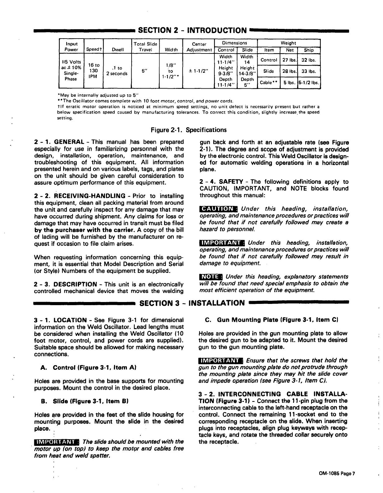
Figure
2-1.
Specifications
2
-
1.
GENERAL
-
This
manual
has
been
prepared
especially
for
use
in
familiarizing
personnel
with
the
design,
installation,
operation,
maintenance,
and
troubleshooting
of
this
equipment.
All
information
presented
herein
and
on
various
labels,
tags,
and
plates
on
the
unit
should
be
given
careful
consideration
to
assure
optimum
performance
of
this
equipment.
2
-
2.
RECEIVING-HANDLING
-
Prior
to
installing
this
equipment,
clean
all
packing
material
from
around
the
unit
and
carefully
inspect
for
any
damage
that
may
have
occurred
during
shipment.
Any
claims
for
loss
or
damage
that
may
have
occurred
in
transit
must
be
filed
by
the
purchaser
with
the
carrier.
A
copy
of
the
bill
of
lading
will
be
furnished
by
the
manufacturer
on
re
quest
if
occasion
to
file
claim
arises.
When
requesting
information
concerning
this
equip
ment,
it
is
essential
that
Model
Description
and
Serial
(or
Style)
Numbers
of
the
equipment
be
supplied.
2
-
3.
DESCRIPTION
-
This
unit
is
an
electronically
controlled
mechanical
device
that
moves
the
welding
gun
back
and
forth
at
an
adjustable
rate
(see
Figure
2-1).
The
degree
and
scope
of
adjustment
is
provided
by
the
electronic
control.
This
Weld
Oscillator
is
design
ed
for
automatic
welding
operations
in
a
horizontal
plane.
2
-
4.
SAFETY
-
The
following
definitions
apply
to
CAUTION,
IMPORTANT,
and
NOTE
blocks
found
throughout
this
manual:
CAUTION:
____
Under
this
heading,
installation,
operating,
and
maintenance
procedures
or
practices
will
be
found
that
if
not
carefully
followed
may
create
a
hazard
to
personnel.
IMPORTANT
_______________
Under
this
heading,
installation,
operating,
and
maintenance
procedures
or
practices
will
be
found
that
if
not
carefully
followed
may
result
in
damage
to
equipment.
I~s1L~
Under
this
heading,
explanatoiy
statements
will
be
found
that
need
special
emphasis
to
obtain
the
most
efficient
operation
of
the
equipment.
SECTION
3
-
INSTALLATION
3
-
1.
LOCATION
-
See
Figure
3-1
for
dimensional
information
on
the
Weld
Oscillator.
Lead
lengths
must
be
considered
when
installing
the
Weld
Oscillator
(10
foot
motor,
control,
and
power
cords
are
supplied).
Suitable
space
should
be
allowed
for
making
necessary
connections.
A.
Control
(Figure
3-1,
Item
A)
Holes
are
provided
in
the
base
supports
for
mounting
purposes.
Mount
the
control
in
the
desired
place.
B.
Slide
(Figure
3-1,
Item
B)
Holes
are
provided
in
the
feet
of
the
slide
housing
for
mounting
purposes.
Mount
the
slide
in
the
desired
place.
-
IMPORTANT:
The
slide
should
be
mounted
with
the
motor
up
(on
top)
to
keep
the
motor
and
cables
free
from
heat
and
weld
spatter.
C.
Gun
Mounting
Plate
(Figure
3-1,
Item
C)
Holes
are
provided
in
the
gun
mounting
plate
to
allow
the
desired
gun
to
be
adapted
to
it.
Mount
the
desired
gun
to
the
gun
mounting
plate.
IMPORTANT:
Ensure
that
the
screws
that
hold
the
gun
to
the
gun
mounting
p/ate
do
not
protrude
through
the
mounting
p/ate
since
they
may
hit
the
slide
cover
and
impede
operation
(see
Figure
3-1,
Item
C).
3
-
2.
INTERCONNECTING
CABLE
INSTALLA
TION
(Figure
3-1)
-
Connect
the
11-pin
plug
from
the
interconnecting
cable
to
the
left-hand
receptacle
on
the
control.
Connect
the
remaining
11-socket
end
to
the
corresponding
receptacle
on
the
slide.
When
inserting
plugs
into
receptacles,
align
plug
keyways
with
recep
tacle
keys,
and
rotate
the
threaded
collar
securely
onto
the
receptacle.
OM-1085
Page
7

3
-
3.
CONTROL
CABLE
INSTALLATION
(Figure
3-1)
-
Connect
the
4-pin
plug
from
the
control
cable
to
the
center
receptacle
on
the
control.
Connet
the
re
maining
4-socket
end
to
the
corresponding
receptacle
on
the
slide.
When
inserting
plugs
into
receptacles,
align
plug
keyways
with
receptacle
keys,
and
rotate
the
threaded
collar
securely
onto
the
receptacle.
This
graph
represents
recommended
weight
limits
at
various
distances
from
the
mounting
plate.
The
Oscillator
will
carry
these
loads
at
max.
speed
with
no
abnormal
wear.
Figure
3-2.
Torque
Curves
3
-4.
POWER
CORD
INSTALLATION
(Figure
3-1)
-
Connect
the
3-prong,
twistlock
plug
from
the
power
cable
to
the
right-hand
receptacle
on
the
control.
Insert
the
plug
and
rotate
it
clockwise.
Connect
the
re
maining
end
to
a
115
volts
ac,
single-phase
power
sup
ply.
3
-5.
REMOTE
CONTROL
INSTALLAT(ON
-
This
Oscillator
is
designed
with
remote
control
capability.
When
installing
any
remote
control,
the
following
steps
must
be
taken:
a.
Disconnect
the
power
cable
from
the
115
volts
ac
power
supply.
b.
Remove
the
outer
enclosure
from
the
con
c.
Route
leads
through
cable
clamp
connector
on
lower
right-hand
side
of
control
front
panel
(see
Figure
3-1),
and
up
through
plastic
clamp
by
terminal
strips
(see
Figure
4-2).
d.
Make
connections
as
instructed
to
terminal
strips
iT
and
2T
(see
Figure
3-3).
a.
The
necessary
remote
control(s)
must
be
supplied
by
the
customer.
if
Remote
Start-Stop
capability
is
desired,
connect
a
normally-closed
switch
to
terminals
21
and
22
on
ter
minal
strip
2T.
For
the
remote
switch
to
be
operational,
switch
(S2)
must
be
in
the
RUN
position.
5,.
9/32
5/1
9.1/2
Item
A
8-l/4~
_
_
I
10
~
4
5/8
5/8
*14.3/8
to
bottom
of
mounting
feet
1
3/4
Figure
3-1.
Weld
Oscillators
Dimensions
TB-052 314
CENTER
OF
GRAVITY
(INCHES
FROM
MOUNTING
PLATE)
trol.
20
40
60
80
100
120
PAYLOAD
POUNDS
3
-
6.
REMOTE
START-STOP
SWITCH
IN
TA-052
831
STALLATION
OM-1085
Page
8

24
TA-052
318
~_
8
53
3
54
7
46
2
45
12
49
13
14
15
16
~:ll:~~fi
t~c~ułnfi
~
~
jfi~łj
11fiRłfl-~~1
tł~
jfiij
~f
9
50
47
48
55 56
24
51
26 52
21
22
Figure
3-3.
Terminal
Strips
3
-7.
REMOTE
DWELL
ON
LEFT
CONTROL
IN
STALLATION
-
If
Remote
Dwell
On
Left
capability
is
desired,
remove
the
jumper
link
across
terminals
51
and
24
on
terminal
strip
21,
and
connect
a
potentiometer
(of
equal
value
to
R7;
see
Parts
List)
to
terminals
9
and
24
on
terminal
strip
2T
(see
Figure
3-4).
~IsIT~
With
mu/ti-
Travel
Width
or
multi-Center
Posi
iT
tion
remote
potentiometers,
switching
must
be
done
with
the
type
of
relay
that
has
gold
alloy
cross
bar
type
contacts
or
the
equivalent.
3-10.
REMOTE
CENTER
POSITION
CONTROL
IN-
21
STALLATION
-
If
Remote
Center
Position
capability
is
desired,
remove
the
jumper
link
across
terminals
47
and
48
(on
terminal
strip
2T)
and
across
15
and
16
(on
ter
minal
strip
iT).
Connect
a
potentiometer
(of
equal
value
to
RiO;
see
Parts
List)
to
terminals
48
and
55
(on
ter
minal
strip
2T)
and
terminal
15
(on
terminal
strip
iT).
(See
Figure
3-7.)
15
55
48
Figure
3-7.
Remote
Potentiometer
Connections
TA-044366
3-11.
REMOTE
SPEED
TO
LEFT
CONTROL
IN
STALLATION
-
If
Remote
Speed
To
Loft
capability
is
Figure
3-4.
Remote
Potentiometer
Connections
desired,
remove
the
jumper
link
across
terminals
53
and
8
on
terminal
strip
iT,
and
connect
a
potentiometer
(of
3
-
8.
REMOTE
DWELL
ON
RIGHT
CONTROL
IN-
equal
value
to
R5;
see
Parts
List)
to
terminals
53
and
46
STALLATION
-
If
Remote
Dwell
On
Right
capability
is
on
terminal
strip
iT
(see
Figure
3-8).
desired,
remove
the
jumper
link
across
terminals
26
and
52
on
terminal
strip
21,
and
connect
a
potentiometer
(of
equal
value
to
R6;
see
Parts
List)
to
terminals
9
and
26
on
terminal
strip
21
(see
Figure
3-5).
26
46
FIgure
3-5.
Remote
Potentiometer
Connections
3
-
9.
REMOTE
TRAVEL
WIDTH
CONTROL
IN
STALLATION
-
If
Remote
Travel
Width
capability
is
desired,
remove
the
jumper
link
across
terminals
13
and
14,
and
across
12
and
49
on
terminal
strip
iT.
Connect
a
potentiometer
(of
equal
value
to
Ri
2;
see
Parts
List)
to
terminals
12
and
13
(on
terminal
strip
iT)
and
ter
minal
9
(on
terminal
strip
21).
(See
Figure
3-6.)
Figure
3-8.
Remote
Potentiometer
Connections
3-12.
REMOTE
SPEED
TO
RIGHT
CONTROL
IN
STALLATION
-
If
Remote
Speed
To
Right
capability
is
desired,
remove
the
jumper
link
across
terminals
3
and
54
on
terminal
strip
1
T,
and
connect
a
potentiometer
(of
equal
value
to
R4;
see
Parts
List)
to
terminals
54
and
45
on
terminal
strip
iT
(see
Figure
3-9).
13
9
12
54
45
FIgure
3-6.
Remote
Potentiometer
Connections
Figure
3-9.
Remote
Potentiometer
Connections
L~Is11~
If
multi-remote
speed
adjustments
(more
than
one
of
either
left
or
right)
are
desired,
then
an
optional
multi-pass
circuit
card
must
be
installed.
(Contact
Fac
to,y
Sales
Department.)
OM-1085
Page
9
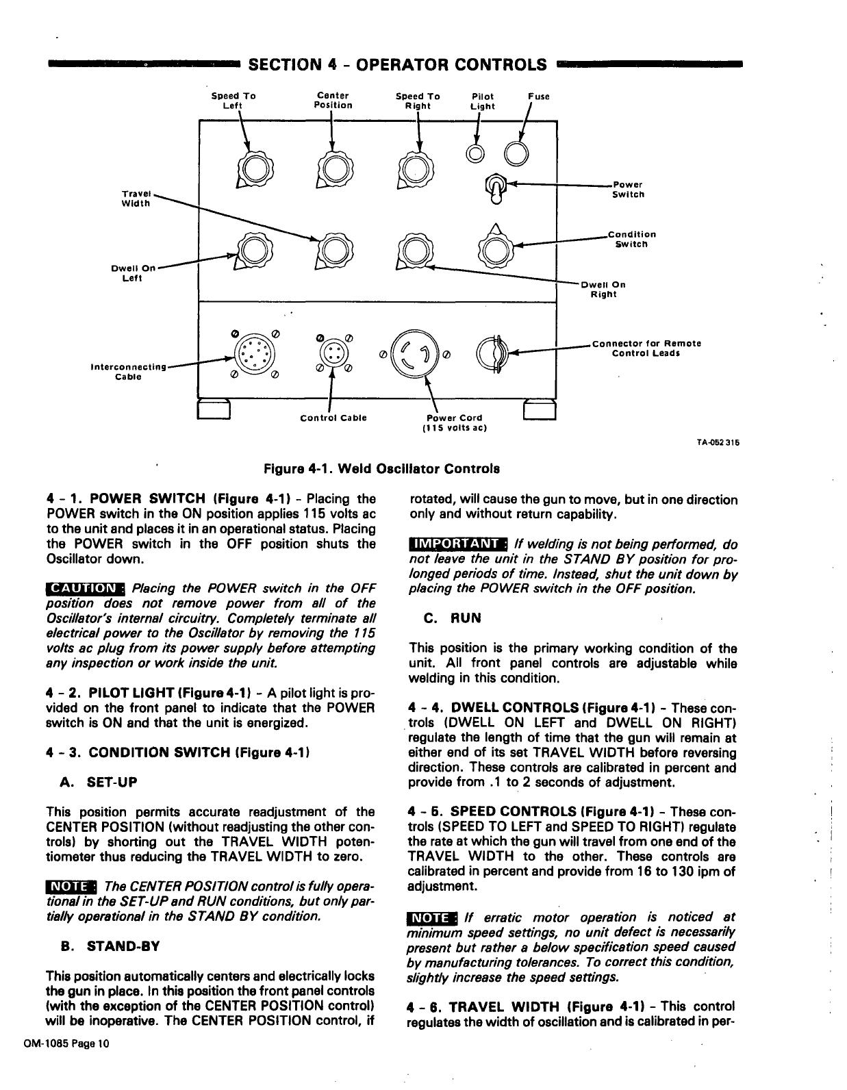
SECTION
4
-
OPERATOR CONTROLS
TA-052
315
4
-
1.
POWER
SWITCH
(Figure
4-1)
-
Placing
the
POWER
switch
in
the
ON
position
applies
115
volts
ac
to
the
unit
and
places
it
in
an
operational
status.
Placing
the
POWER
switch
in
the
OFF
position
shuts
the
Oscillator
down.
CAUTION
__________
Piecing
the
POWER
switch
in
the
OFF
position
does
not
remove
power
from
all
of
the
Oscillators
internal
circuitry.
Completely
terminate
all
electrical
power
to
the
Oscillator
by
removing
the
115
volts
ac
plug
from
its
power
supply
before
attempting
any
inspection
or
work
inside
the
unit.
4
-
2.
PILOT
LIGHT
(Figure
4-1)
-
A
pilot
light
is
pro
vided
on
the
front
panel
to
indicate
that
the
POWER
switch
is
ON
and
that
the
unit
is
energized.
4
-
3.
CONDITION
SWITCH
(Figure
4-1)
A.
SET-UP
rotated,
will
cause
the
gun
to
move,
but
in
one
direction
only
and
without
return
capability.
IMPORTANT
_____________
If
welding
is
not
being
performed,
do
not
leave
the
unit
in
the
STAND
BY
position
for
pro
longed
periods
of
time.
Instead,
shut
the
unit
down
by
placing
the
POWER
switch
in
the
OFF
position.
C.RUN
This
position
is
the
primary
working
condition
of
the
unit.
All
front
panel
controls
are
adjustable
while
welding
in
this
condition.
4
-
4.
DWELL
CONTROLS
(Figure
4-1)
-
These
con
trols
(DWELL
ON
LEFT
and
DWELL
ON
RIGHT)
regulate
the
length
of
time
that
the
gun
will
remain
at
either
end
of
its
set
TRAVEL
WIDTH
before
reversing
direction.
These
controls
are
calibrated
in
percent
and
provide
from
.1
to
2
seconds
of
adjustment.
This
position
permits
accurate
readjustment
of
the
CENTER
POSITION
(without
readjusting
the
other
con
trols)
by
shorting
out
the
TRAVEL
WIDTH
poten
tiometer
thus
reducing
the
TRAVEL
WIDTH
to
zero.
I
The
CENTER
POSITION
control/s
fully
opera
tional
in
the
SET-UP
and
RUN
conditions,
but
only
par-
(jelly
operational
in
the
STAND
BY
condition.
B.
STAND-BY
This
position
automatically
centers
and
electrically
locks
the
gun
in
place.
In
this
position
the
front
panel
controls
(with
the
exception
of
the
CENTER
POSITION
control)
will
be
inoperative.
The
CENTER
POSITION
control,
if
4
-
6.
SPEED
CONTROLS
(Figure
4-1)
-
These
con
trols
(SPEED
TO
LEFT
and
SPEED
TO
RIGHT)
regulate
the
rate
at
which
the
gun
will
travel
from
one
end
of
the
TRAVEL
WIDTH
to
the
other.
These
controls
are
calibrated
in
percent
and
provide
from
16
to
130
ipm
of
adjustment.
L~III1~
If
erratic
motor
operation
is
noticed
at
minimum
speed
settings,
no
unit
defect
is
necessarily
present
but
rather
a
be/ow
specification
speed
caused
by
manufacturing
tolerances.
To
correct
this
condition,
slightly
increase
the
speed
settings.
4
-
6.
TRAVEL
WIDTH
(Figure
4-1)
-
This
control
regulates
the
width
of
oscillation
and
is
calibrated
in
per-
Remote
Control
Leads
Figure
4-1.
Weld
Oscillator
Controls
OM-1085
Page
10
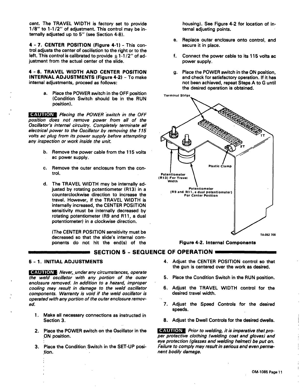
cent.
The
TRAVEL
WIDTH
is
factory
set
to
provide
1/8
to
1-1/2
of
adjustment.
This
control
may
be
in
ternally
adjusted
up
to
5
(see
Section
4-8).
4
-
7.
CENTER
POSITION
(Figure
4-1)
-
This
con
trol
adjusts
the
center
of
oscillation
to
the
right
or
to
the
left.
This
control
is
calibrated
to
provide
–
1-1/2
of
ad
justment
from
the
actual
center
of
the
slide.
4
-8.
TRAVEL
WIDTH
AND
CENTER
POSITION
INTERNAL
ADJUSTMENTS
(Figure
4-2)
-
To
make
internal
adjustments,
proceed
as
follows:
a.
Place
the
POWER
switch
in
the
OFF
position
(Condition
Switch
should
be
in
the
RUN
position).
__________
P/acing
the
POWER
switch
in
the
OFF
position
does
not
remove
power
from
all
of
the
Oscillators
internal
circuit,y.
Completely
terminate
all
electrical
power
to
the
Oscillator
by
removing
the
115
volts
ac
plug
from
its
power
supply
before
attempting
any
inspection
or
work
inside
the
unit.
b.
Remove
the
power
cable
from
the
115
volts
ac
power
supply.
c.
Remove
the
outer
enclosure
from
the
con
trol.
d.
The
TRAVEL
WIDTH
may
be
internally
ad
justed
by
rotating
potentiometer
(R13)
in
a
counterclockwise
direction
to
increase
the
travel.
However,
if
the
TRAVEL
WIDTH
is
internally
increased,
the
CENTER
POSITION
sensitivity
must
be
internally
decreased
by
rotating
potentiometer
(R9
and
Ri
1,
a
dual
potentiometer)
in
a
clockwise
direction.
(The
CENTER
POSITION
sensitivity
must
be
decreased
so
that
the
slides
internal
com
ponents
do
not
hit
the
end(s)
of
the
CAUTION
housing).
See
Figure
4-2
for
location
of
in
ternal
adjusting
points.
e.
Replace
outer
enclosure
onto
control,
and
secure
it
in
place.
f.
Connect
the
power
cable
to
its
115
volts
ac
power
supply.
g.
Place
the
POWER
switch
in
the
ON
position,
and
check
for
satisfactory
operation.
If
it
has
not
been
achieved,
repeat
Steps
A
to
G
until
the
desired
operation
is
obtained.
SECTION
5
-
SEQUENCE
OF
OPERATION
5
-
1.
INITIAL
ADJUSTMENTS
CAUTION
___________
Never,,
under
any
circumstances,
operate
the
weld
oscillator
with
any
portion
of
the
outer
enclosure
removed.
In
addition
to
a
hazard,
improper
cooling
may
result
in
damage
to
the
weld
oscillator
components.
Warranty
is
void
if
the
weld
oscillator
is
operated
with
any
portion
of
the
outer
enclosure
remov
ed.
1.
Make
all
necessary
connections
as
instructed
in
Section
3.
4.
Adjust
the
CENTER
POSITION
control
so
that
the
gun
is
centered
over
the
work
as
desired.
5.
Place
the
Condition
Switch
in
the
RUN
position.
6.
Adjust
the
TRAVEL
WIDTH
control
for
the
desired
travel
width.
7.
Adjust
the
Speed
Controls
for
the
desired
speeds.
8.
Adjust
the
Dwell
Controls
for
the
desired
dwells.
2.
Place
the
POWER
switch
on
the
Oscillator
in
the
ON
position.
3.
Place
the
Condition
Switch
in
the
SET-UP
posi
~tion.
CAUTION
___________
Prior
to
welding,
it
is
imperative
that
pro
per
protective
clothing
(welding
coat
and
gloves)
and
eye
protection
(glasses
and
welding
helmet)
be
put
on.
Failure
to
comply
may
result
in
serious
and
even
perma
nent
bodily
damage.
Terminal
Strips
Potentiometer
(R9
and
Ri
1,
a
dual
potentiometer)
For
Center
Position
Figure
4-2.
Internal
Components
TA-052
105
OM.1085
Page
11
9.
Commence
welding.
5
-2.
SHUTTING
DOWN
S
When
the
Condition
switch
is
moved
from
the
STAND BY
position
to
the
RUN
position,
the
slide
will
aMays
start
in
a
direction
away
from
the
drive
motor.
L~ISIl~
All
of
the
front
panel
controls
may
be
adjusted
while
welding.
1.
Place
the
Condition
Switch
in
the
STAND
BY
position.
2.
Place
the
POWER
switch
on
the
Oscillator
in
the
OFF
position.
SECTION
6
-
MAINTENANCE
CAUTION
___________
Placing
the
POWER
switch
in
the
OFF
position
does
not
remove
power
from,
all
of
the
Oscillators
internal
circuitry.
Completely
terminate
all
electrical
power
to
the
Oscillator
by
removing
the
115
volts
ac
plug
from
its
power
supply
before
attempting
any
inspection
or
work
inside
the
unit.
S
Periodically
inspect
the
labels
on
this
unit
for
legibility.
All
labels
must
be
maintained
in
a
clearly
readable
state
and
replaced
when
necessary.
See
the
Parts
List
for
part
number
of
labels.
6
-
5.
SLIDE
POTENTIOMETER
(See
Parts
List)
-
If
it
should
become
necessary
to
replace
the
slide
potentiometer,
proceed
as
follows:
1.
Remove
cover
over
drive
belt.
2.
Loosen
set
screws,
and
remove
gear
from
poten
tiometer
shaft.
3.
Remove
the
two
screws
holding
the
poten
tiometer
mounting
plate.
8
-
1.
CONTROL
-
The
control
requires
no
periodic
maintenance.
6
-
2.
DRIVE
MOTOR
-
The
drive
motor
requires
no
initial
service
nor
any
periodic
maintenance.
IMPORTANT:
Do
not
disassemble
the
drive
motor.
Synchronous
stepping
motors
will
be
adversely
affected
if
taken
apart.
8
-
3.
SLIDE
-
The
outside
of
the
unit,
particularly
around
the
neoprene
seals,
should
be
kept
clean
by
blowing
it
off
with
a
clean,
dry
airstream.
Periodically,
depending
on
conditions
and
usage,
it
may
become
necessary
to
clean
and
lubricate
the
slide.
Remove
gun,
mounting
plate,
and
slide
cover.
Wipe
the
two
shafts
clean.
Lubricate
the
two
linear
ball
bearings
with
a
light
weight
(No.
20)
oil;
the
oil
holes
are
facing
up
for
ease
of
service.
Do
not
overoil.
Wipe
ball
screw
shaft
clean,
and
apply
a
thin
coat
of
heavy
weight
(No.
90)
oil
to
this
shaft.
Replace
cover,
mounting
plate,
and
gun.
6
-
4.
DRIVE
BELT
-
The
drive
belt
is
a
toothed-type
timing
belt
and
should
not
need
servicing.
However,
should
adjustment
or
replacement
be
required,
provi
sions
are
made
for
tensioning
the
belt.
Remove
cover
over
drive
belt.
Loosen
the
four
bolts
in
the
slotted
holes,
and
slide
the
belt
housing
toward
the
motor
end.
The
belt
should
be
snug,
but
not
overtightened.
Retighten
bolts.
Before
replacing
cover,
inspect
drive
gears,
plastic
gears,
etc.,
for
dirt;
if
necessary
brush
off
and
blow
out
with
a
clean,
dry
airstream.
Replace
cover.
4.
Remove
the
nut
holding
the
potentiometer
to
mounting
plate,
slide
potentiometer
out,
and
allow
it
to
hang
free.
5.
Install
new
potentiometer
(see
Parts
List)
in
mounting
plate.
6.
Unsolder
wires
from
old
potentiometer,
and
resolder
wires
to
the
labeled
terminals
on
new
potentiometer
as
follows:
white
to
slider
(5),
red
to
counterclockwise
(CCW),
and
black
to
clockwise
(CW).
7.
Reinstall
gear
onto
potentiometer
shaft,
and
tighten
set
screws
(hub
on
gear
should
be
flush
with
end
of
shaft).
8.
Manually
move
the
gun
mounting
plate
to
the
center
of
the
slide.
9.
Turn
gear
on
slide
potentiometer
to
one
extreme,
and
then
back
it
off
five
turns.
10.
Align
gear
on
slide
potentiometer
with
small
gear.
on
ball
screw.
.
S
A
small
amount
of
backlash
should
be
main
tained
between
these
two
gears.
11.
Insert
screws,
and
secure
the
potentiometer
mounting
plate.
OM-1085
Page
12
SECTION
7
-
TROUBLESHOOTING
CAUTION
Hazardous
voltages
are
present
on
the
in
ternal
circuitry
of
the
weld
oscillator
as
long
as
power
is
connected
to
the
unit.
Disconnect
power
before
at
tempting
any
inspection
or
work
on
the
inside
of
the
unit.
Troubleshooting
of
internal
circuitry
should
be
per
formed
by
qualified
personnel
only.
The
following
chart
is
designed
to
diagnose
and
provide
remedies
for
some
of
the
troubles
that
may
develop
in
this
weld
oscillator.
It
is
assumed
that
proper
installation
has
been
made,
ac
cording
to
Section
3
of
this
manual,
and
that
the
weld
oscillator
has
been
functioning
properly
until
this
trou
ble
developed.
Use
this
chart
in
conjunction
with
the
circuit
diagram
while
performing
troubleshooting
procedures.
If
the
trouble
is
not
remedied
after
performing
these
pro
cedures,
the
nearest
Factory
Authorized
Service
Sta
tion
should
be
contacted.
In
all
cases
of
equipment
malfunction,
the
manufacturers
recommendations
should
be
strictly
followed.
TROUBLE
PROBABLE
CAUSE
REMEDY
Unit
completely
inoperative
(pilot
light
(PL)
not
on).
Open
line
fuse.
Replace
open
line
fuse.
Unit
completely
inoperative
(pilot
light
(PL)
on).
Fuse
(Fl)
open.
*Replace
fuse
(Fl).
Erratic
operation.
~
Plug(s)
not
secure
in
recap-
tacle(s).
Check
all
plugs,
and
ensure
that
they
are
secure
in
receptacles.
Slide
stalled
and
motor
hums.
Obstruction
or
excessive
loading.
Remove
obstruction
and/or
reduce
loading.
POWER
switch
(Si)
must
be
turned
OFF
and
then
back
ON
to
restart
oscillator.
*lf
it
becomes
necessary
to
replace
any
fuse
in
the
Weld
Oscillator,
ensure
that
a
fuse
of
the
proper
size
is
used.
OM-1085
Page
13
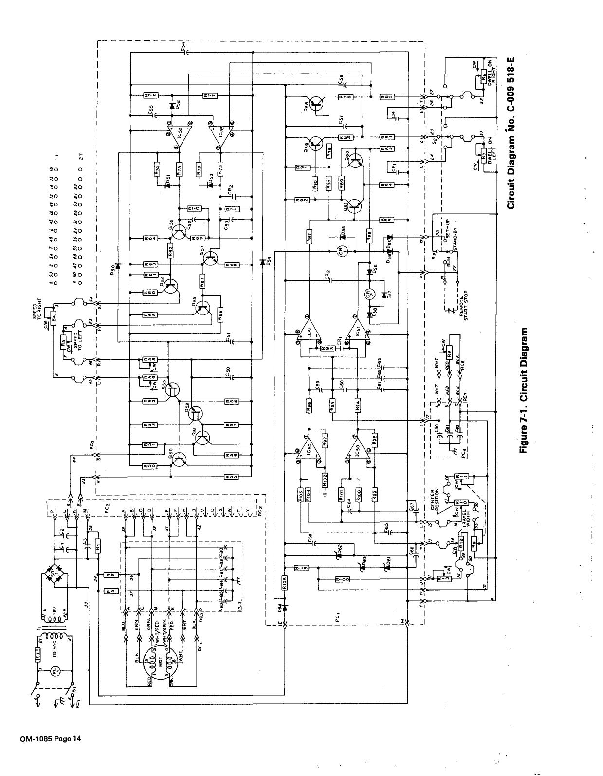
34
R
9
3
2
c1~
~
~L
~II
_~–ii
-
-
I
PC1
IM
-m
~
I
191
-4W
1I
057
IC5~_
-~
I
~
S2~J
~N
~
~ETUP
~_J5TAN0-eV
0541
0
01
63 63
~Fl8
135
VAC
~
~
V
~II~
903
-
>>-~.
-x~------
BLC
>>GRN
3~
-~
I
~
I
HOT
~-WHT/RED
B
I
6
~
1WHT/0RN~
I
>~9ED
>~
-
361
-
I
~
WHT.
~>WH1
~
~
BLE
I
~1caJ~
___
T
T~~
___
44
PC2!
II
j----3,
~J-A
I
II
SPEED
TO
RIGHT
CW
Fl
___________________________
4
53
3
54
7
46
2
45
12
49
13
14
15
/6
00000000000000
IT
2
c58
IL,
~
s~
47
4Æ
55
56
24
51
26
5!?!
22
o
o
0
0
0
0
0
0
0
0
0
0
0
0
2T
TO
LEFT
43A_
46
A54
-~
-~
-~
_x
--
~
050
4
RC4
R051D
1c931c95
C9
C81
C85
c80
I
IT
I~__
I
jF
~
6
~
B
161
L~J
Li
L~i
L~]
tcwletcwe
1.11
~
~1~~~___
~
L~r
4
~
GM~
6
~
053
~
,~I7I
o
0579
,j
I
*053
~
~~IJ
~
a
C5~
EJ1
i11
Icso
-~
~
L
~LLLL
I
-
ii
~58
1~~1
062
054
RIO
RiOO
ICSO
~98
D6I
~D55
2
999
a
C57
~
I.
k~
I~
le
to
F-
-
D5~
~C~4
-~
~
R~~I
L
~Wt
POSITION
912
\~L_t~~4~1
~
TRAVEL
I.~J
,.I
Li
!0
i~~:_~
,/
C56
D59~~~
a
T
-
~
WIlT
WIlT
-<.__
~cw
I
pc4~
~
RED
I
C92~
~<8L*~
~
~-
_
I
----~-
RE
MOTE
START-STOP
____C_~__~
__~~
124
52125
(26(27
DWELL
ON
DWZLLONI
Circuit
Diagram
isio.
C-009
518-E
Figure
7-1.
Circuit
Diagram
/