Page is loading ...

Table of Contents
Cover photo may show optional equipment not supplied
with standard unit.
For an Operator’s Manual and Decal Kit in French
Language, please see your Land Pride dealer.
Read the Operator’s Manual entirely. When you see this symbol,
the subsequent instructions and warnings are serious - follow
without exception. Your life and the lives of others depend on it!
!
Rear Blades
RBT4596 & RBT45108
301-205M
Operator’s Manual
Printed 11/27/18
35106

11/27/18RBT4596 & RBT45108 Rear Blades 301-205M
Machine Identification
Record your machine details in the log below. If you replace this manual, be sure to transfer this information to the new
manual.
If you, or the dealer, have added Options not originally ordered with the machine, or removed Options that were
originally ordered, the weights and measurements are no longer accurate for your machine. Update the record by
adding the machine weight and measurements provided in the Specifications & Capacities Section of this manual with
the Option(s) weight and measurements.
Dealer Contact Information
Model Number
Serial Number
Machine Height
Machine Length
Machine Width
Machine Weight
Delivery Date
First Operation
Accessories
Name:
Street:
City/State:
Telephone:
Email:
WARNING: Cancer and reproductive harm - www.P65Warnings.ca.gov
!
California Proposition 65

Table of Contents
11/27/18
© Copyright 2018 All rights Reserved
Land Pride provides this publication “as is” without warranty of any kind, either expressed or implied. While every precaution has been taken in the
preparation of this manual, Land Pride assumes no responsibility for errors or omissions. Neither is any liability assumed for damages resulting from the use
of the information contained herein. Land Pride reserves the right to revise and improve its products as it sees fit. This publication describes the state of this
product at the time of its publication, and may not reflect the product in the future.
Land Pride is a registered trademark.
All other brands and product names are trademarks or registered trademarks of their respective holders.
Printed in the United States of America.
RBT4596 & RBT45108 Rear Blades 301-205M
Table of Contents
Important Safety Information . . . . . . . . . . . . . 1
Safety at All Times . . . . . . . . . . . . . . . . . . . . . . . . . 1
Look for the Safety Alert Symbol . . . . . . . . . . . . . . . 1
Safety Labels . . . . . . . . . . . . . . . . . . . . . . . . . . . . . 4
Introduction . . . . . . . . . . . . . . . . . . . . . . . . . . . 6
Application . . . . . . . . . . . . . . . . . . . . . . . . . . . . . . . 6
Using This Manual . . . . . . . . . . . . . . . . . . . . . . . . . 6
Owner Assistance . . . . . . . . . . . . . . . . . . . . . . . . . . 6
Serial Number . . . . . . . . . . . . . . . . . . . . . . . . . . . 6
Section 1: Assembly & Set-Up . . . . . . . . . . . . 7
Tractor Requirements . . . . . . . . . . . . . . . . . . . . . . . 7
Weight & Horsepower . . . . . . . . . . . . . . . . . . . . . 7
Weight . . . . . . . . . . . . . . . . . . . . . . . . . . . . . . . . . 7
3-Point Hitch . . . . . . . . . . . . . . . . . . . . . . . . . . . . 7
Hydraulic Outlets . . . . . . . . . . . . . . . . . . . . . . . . . 7
Torque Requirements . . . . . . . . . . . . . . . . . . . . . . . 7
Tractor Shutdown Procedure . . . . . . . . . . . . . . . . . 7
Assembly & Set-Up Safety . . . . . . . . . . . . . . . . . . . 8
Hitch, Frame & Blade . . . . . . . . . . . . . . . . . . . . . . . 8
3-Point Hook-Up . . . . . . . . . . . . . . . . . . . . . . . . . . . 9
Standard 3-Point Hook-Up . . . . . . . . . . . . . . . . . . 9
Quick Hitch Hook-Up . . . . . . . . . . . . . . . . . . . . . . 9
Blade Offset Cylinder . . . . . . . . . . . . . . . . . . . . . . 10
Blade Angling Cylinder . . . . . . . . . . . . . . . . . . . . . 10
Blade Tilting Cylinder . . . . . . . . . . . . . . . . . . . . . . 11
Section 2: Set-Up of Accessories . . . . . . . . . 12
Manual Offset, Angling and Tilting . . . . . . . . . . . . 12
Gauge Wheel . . . . . . . . . . . . . . . . . . . . . . . . . . . . 13
Hydraulic Cushion Valve . . . . . . . . . . . . . . . . . . . . 14
Hydraulic Selector Valve . . . . . . . . . . . . . . . . . . . . 15
Skid Shoe . . . . . . . . . . . . . . . . . . . . . . . . . . . . . . . 16
End Plates . . . . . . . . . . . . . . . . . . . . . . . . . . . . . . . 16
Section 3: Adjustments . . . . . . . . . . . . . . . . . 17
Safety First . . . . . . . . . . . . . . . . . . . . . . . . . . . . . . 17
Blade Offset Adjustment . . . . . . . . . . . . . . . . . . . . 17
Manual Offset . . . . . . . . . . . . . . . . . . . . . . . . . . 17
Hydraulic Offset . . . . . . . . . . . . . . . . . . . . . . . . . 17
Blade Angle and Reversing . . . . . . . . . . . . . . . . . . 17
Manual Angle and Reversing . . . . . . . . . . . . . . . 17
Hydraulic Angle and Reversing . . . . . . . . . . . . . 17
Blade Tilt Adjustments . . . . . . . . . . . . . . . . . . . . . 18
Manual Tilt . . . . . . . . . . . . . . . . . . . . . . . . . . . . . 18
Hydraulic Tilt . . . . . . . . . . . . . . . . . . . . . . . . . . . 18
Gauge Wheel Depth Adjustments . . . . . . . . . . . . . 18
Manual Depth Control . . . . . . . . . . . . . . . . . . . . 18
Hydraulic Depth Control . . . . . . . . . . . . . . . . . . . 18
Blade Pitch . . . . . . . . . . . . . . . . . . . . . . . . . . . . . . 18
Section 4: Operating Procedures . . . . . . . . . 19
Operating Checklist . . . . . . . . . . . . . . . . . . . . . . . . 19
General Safety . . . . . . . . . . . . . . . . . . . . . . . . . . . 19
Inspection After Hook-Up . . . . . . . . . . . . . . . . . . . 20
Transport With Rear Blade . . . . . . . . . . . . . . . . . . 20
Rear Blade Functions . . . . . . . . . . . . . . . . . . . . . . 21
Grading . . . . . . . . . . . . . . . . . . . . . . . . . . . . . . . 21
Edge work . . . . . . . . . . . . . . . . . . . . . . . . . . . . . 21
Ditch Work . . . . . . . . . . . . . . . . . . . . . . . . . . . . . 21
Backfilling . . . . . . . . . . . . . . . . . . . . . . . . . . . . . . 21
Unhook Rear Blade . . . . . . . . . . . . . . . . . . . . . . . . 21
Basic Operating Instructions . . . . . . . . . . . . . . . . . 22
General Operating Instructions . . . . . . . . . . . . . . . 22
Section 5: Maintenance & Lubrication . . . . . 23
Maintenance . . . . . . . . . . . . . . . . . . . . . . . . . . . . . 23
Tractor Maintenance . . . . . . . . . . . . . . . . . . . . . . . 23
Long-Term Storage . . . . . . . . . . . . . . . . . . . . . . . . 23
Ordering Replacement Parts . . . . . . . . . . . . . . . . . 23
Lubrication . . . . . . . . . . . . . . . . . . . . . . . . . . . . . . . 24
Blade Pivot Shaft . . . . . . . . . . . . . . . . . . . . . . . . 24
Blade Tilt Shaft . . . . . . . . . . . . . . . . . . . . . . . . . . 24
Front Pivot Shaft . . . . . . . . . . . . . . . . . . . . . . . . 24
Moldboard and Blade . . . . . . . . . . . . . . . . . . . . . 24
Ratchet Jack . . . . . . . . . . . . . . . . . . . . . . . . . . . 25
Gauge Wheel Front Pivot . . . . . . . . . . . . . . . . . . 25
Gauge Wheel Caster Tube . . . . . . . . . . . . . . . . . 25
Gauge Wheel Hub . . . . . . . . . . . . . . . . . . . . . . . 25
Section 6: Specifications & Capacities . . . . . 26
Section 7: Features & Benefits . . . . . . . . . . . 27
Section 8: Troubleshooting . . . . . . . . . . . . . . 28
Section 9: Torque Values Chart . . . . . . . . . . . 29
Section 10: Warranty . . . . . . . . . . . . . . . . . . . 31

Table of Contents Continued
11/27/18
Parts Manual QR Locator
The QR (Quick Reference) code on the
cover and to the left will take you to the
Parts Manual for this equipment.
Download the appropriate App on your
smart phone, open the App, point your
phone on the QR code and take a picture.
Dealer QR Locator
The QR code on the left will
link you to available dealers
for Land Pride products.
Refer to Parts Manual QR
Locator on this page for
detailed instructions.
RBT4596 & RBT45108 Rear Blades 301-205M
Table of Contents
See previous page for Table of Contents.

Important Safety Information
11/27/18
1
Important Safety Information
Listed below are common practices that may or may not be applicable to the products
described in this manual.
Tractor Shutdown & Storage
If engaged, disengage power
take-off.
Park on solid, level ground and
lower implement to ground or onto
support blocks.
Put tractor in park or set park
brake, turn off engine, and remove
switch key to prevent unauthorized
starting.
Relieve all hydraulic pressure to
auxiliary hydraulic lines.
Wait for all components to stop
before leaving operator’s seat.
Use steps, grab-handles and
anti-slip surfaces when stepping
on and off the tractor.
Detach and store implement in an
area where children normally do
not play. Secure implement using
blocks and supports.
OFF
REMOVE
Look for the Safety Alert Symbol
The SAFETY ALERT SYMBOL indicates there is a
potential hazard to personal safety involved and extra
safety precaution must be taken. When you see this
symbol, be alert and carefully read the message that
follows it. In addition to design and configuration of
equipment, hazard control, and accident prevention are
dependent upon the awareness, concern, prudence, and
proper training of personnel involved in the operation,
transport, maintenance, and storage of equipment.
Safety Precautions for
Children
Tragedy can occur if the operator
is not alert to the presence of
children. Children generally are
attracted to implements and their
work.
Never assume children will remain
where you last saw them.
Keep children out of the work area
and under the watchful eye of a
responsible adult.
Be alert and shut the implement
and tractor down if children enter
the work area.
Never carry children on the tractor
or implement. There is not a safe
place for them to ride. They may
fall off and be run over or interfere
with the control of the power
machine.
Never allow children to operate the
power machine, even under adult
supervision.
Never allow children to play on the
power machine or implement.
Use extra caution when backing
up. Before the tractor starts to
move, look down and behind to
make sure the area is clear.
Safety at All Times
Careful operation is your best
assurance against an accident.
All operators, no matter how much
experience they may have, should
carefully read this manual and
other related manuals, or have the
manuals read to them, before
operating the power machine and
this implement.
Thoroughly read and understand
the “Safety Label” section. Read
all instructions noted on them.
Do not operate the equipment
while under the influence of drugs
or alcohol as they impair the ability
to safely and properly operate the
equipment.
The operator should be familiar
with all functions of the tractor and
attached implement and be able to
handle emergencies quickly.
Make sure all guards and shields
appropriate for the operation are in
place and secured before
operating implement.
Keep all bystanders away from
equipment and work area.
Start tractor from the driver’s seat
with hydraulic controls in neutral.
Operate tractor and controls from
the driver’s seat only.
Never dismount from a moving
tractor or leave tractor unattended
with engine running.
Do not allow anyone to stand
between tractor and implement
while backing up to implement.
Keep hands, feet, and clothing
away from power-driven parts.
While transporting and operating
equipment, watch out for objects
overhead and along side such as
fences, trees, buildings, wires, etc.
Do not turn tractor so tight as to
cause hitched implement to ride
up on the tractor’s rear wheel.
Store implement in an area where
children normally do not play.
When needed, secure attachment
against falling with support blocks.
Be Aware of
Signal Words
A signal word designates a degree or
level of hazard seriousness. The
signal words are:
Indicates a hazardous situation that, if
not avoided, will result in death or
serious injury.
Indicates a hazardous situation that, if
not avoided, could result in death or
serious injury.
Indicates a hazardous situation that, if
not avoided, may result in minor or
moderate injury.
WARNING
CAUTION
!
!
!
DANGER
!

Important Safety Information
11/27/18
2
Listed below are common practices that may or may not be applicable to the products
described in this manual.
Practice Safe Maintenance
Understand procedure before doing
work. Refer to the Operator’s
Manual for additional information.
Work on a level surface in a clean
dry area that is well-lit.
Lower implement to the ground and
follow all shutdown procedures
before leaving the operator’s seat to
perform maintenance.
Do not work under any hydraulic
supported equipment. It can settle,
suddenly leak down, or be lowered
accidentally. If it is necessary to
work under the equipment, securely
support it with stands or suitable
blocking beforehand.
Use properly grounded electrical
outlets and tools.
Use correct tools and equipment for
the job that are in good condition.
Allow equipment to cool before
working on it.
Disconnect battery ground cable (-)
before servicing or adjusting
electrical systems or before welding
on implement.
Inspect all parts. Make certain
parts are in good condition &
installed properly.
Replace parts on this implement
with genuine Land Pride parts only.
Do not alter this implement in a way
which will adversely affect its
performance.
Do not grease or oil implement
while it is in operation.
Remove buildup of grease, oil, or
debris.
Always make sure any material and
waste products from the repair and
maintenance of the implement are
properly collected and disposed.
Remove all tools and unused parts
before operation.
Do not weld or torch on galvanized
metal as it will release toxic fumes.
Use A Safety Chain
A safety chain will help control
drawn machinery should it
separate from the tractor drawbar.
Use a chain with the strength
rating equal to or greater than the
gross weight of the towed
implement.
Attach the chain to the tractor
drawbar support or other specified
anchor location. Allow only
enough slack in the chain to
permit turning.
Always hitch the implement to the
machine towing it. Do not use the
safety chain tow the implement.
Transport Safely
Comply with federal, state, and
local laws.
Use towing vehicle and trailer of
adequate size and capacity. Secure
equipment towed on a trailer with
tie downs and chains.
Sudden braking can cause a towed
trailer to swerve and upset. Reduce
speed if towed trailer is not
equipped with brakes.
Avoid contact with any overhead
utility lines or electrically charged
conductors.
Always drive with load on end of
loader arms low to the ground.
Always drive straight up and down
steep inclines with heavy end of a
tractor with loader attachment on
the “uphill” side.
Engage park brake when stopped
on an incline.
Maximum transport speed for an
attached equipment is 20 mph. DO
NOT EXCEED. Never travel at a
speed which does not allow
adequate control of steering and
stopping. Some rough terrains
require a slower speed.
As a guideline, use the following
maximum speed weight ratios for
attached equipment:
20 mph when weight of attached
equipment is less than or equal
to the weight of machine towing
the equipment.
10 mph when weight of attached
equipment exceeds weight of
machine towing equipment but
not more than double the weight.
IMPORTANT: Do not tow a load
that is more than double the weight
of the vehicle towing the load.
Tire Safety
Tire changing can be dangerous
and must be performed by
trained personnel using the
correct tools and equipment.
Always maintain correct tire
pressure. Do not inflate tires
above recommended pressures
shown in the Operator’s Manual.
When inflating tires, use a clip-on
chuck and extension hose long
enough to allow you to stand to
one side and NOT in front of or
over the tire assembly. Use a
safety cage if available.
Securely support the implement
when changing a wheel.
When removing and installing
wheels, use wheel handling
equipment adequate for the
weight involved.
Make sure wheel bolts have been
tightened to the specified torque.

Important Safety Information
11/27/18
3
Listed below are common practices that may or may not be applicable to the products
described in this manual.
Avoid High
Pressure Fluids Hazard
Escaping fluid under pressure can
penetrate the skin causing serious
injury.
Before disconnecting hydraulic
lines or performing work on the
hydraulic system, be sure to
release all residual pressure.
Make sure all hydraulic fluid
connections are tight and all
hydraulic hoses and lines are in
good condition before applying
pressure to the system.
Use a piece of paper or
cardboard, NOT BODY PARTS, to
check for suspected leaks.
Wear protective gloves and safety
glasses or goggles when working
with hydraulic systems.
DO NOT DELAY. If an accident
occurs, see a doctor familiar with
this type of injury immediately. Any
fluid injected into the skin or eyes
must be treated within
a few hours or
gangrene may
result.
Wear Personal Protective
Equipment (PPE)
Wear protective clothing and
equipment appropriate for the job
such as safety shoes, safety
glasses, hard hat, and ear plugs.
Clothing should fit snug without
fringes and pull strings to avoid
entanglement with moving parts.
Prolonged exposure to loud noise
can cause hearing impairment or
hearing loss. Wear suitable
hearing protection such as
earmuffs or earplugs.
Operating equipment safely
requires the operator’s full
attention. Avoid wearing
headphones while operating
equipment.
Use Seat Belt and ROPS
Land Pride recommends the use
of a CAB or roll-over-protective-
structures (ROPS) and seat belt
in almost all power machines.
Combination of a CAB or ROPS
and seat belt will reduce the risk
of serious injury or death if the
power machine should be upset.
If ROPS is in the locked-up
position, fasten seat belt snugly
and securely to help protect
against serious injury or death
from falling and machine overturn.
Keep Riders Off
Machinery
Never carry riders on tractor or
implement.
Riders obstruct operator’s view
and interfere with the control of
the power machine.
Riders can be struck by objects or
thrown from the equipment.
Never use tractor or implement to
lift or transport riders.
Avoid Underground
Utilities
Dig Safe, Call 811 (USA).
Always contact your local utility
companies (electrical, telephone,
gas, water, sewer, and others)
before digging so that they may
mark the location of any
underground services in the area.
Be sure to ask how close you can
work to the marks they positioned.
Prepare for Emergencies
Be prepared if a fire starts.
Keep a first aid kit and fire
extinguisher handy.
Keep emergency numbers for
doctor, ambulance, hospital, and
fire department near phone.
911
Use Safety
Lights and Devices
Slow moving tractors, skid steers,
self-propelled machines, and towed
equipment can create a hazard
when driven on public roads. They
are difficult to see, especially at
night. Use the Slow Moving Vehicle
sign (SMV) when on public roads.
Flashing warning lights and turn
signals are recommended
whenever driving on public roads.

Important Safety Information
RBT4596 & RBT45108 Rear Blades 301-205M 11/27/18
4
Table of Contents
818-339C
Warning: High Pressure
818-487C
Danger Avoid Injury
35107
35107
Safety Labels
Your Rear Blade comes equipped with all safety labels in place.
They were designed to help you safely operate your implement.
Read and follow their directions.
1. Keep all safety labels clean and legible.
2. Refer to this section for proper label placement. Replace
all damaged or missing labels. Order new labels from your
nearest Land Pride dealer. To find your nearest dealer,
visit our dealer locator at www.landpride.com.
3. Some new equipment installed during repair requires
safety labels to be affixed to the replaced component as
specified by Land Pride. When ordering new components
make sure the correct safety labels are included in the
request.
4. Refer to this section for proper label placement.
To install new labels:
a. Clean surface area where label is to be placed.
b. Spray soapy water on the surface where the label is to
be placed.
c. Peel backing from label. Press firmly onto the surface.
d. Squeeze out air bubbles with the edge of a credit card
or with a similar type straight edge.
Important Safety Information

Important Safety Information
RBT4596 & RBT45108 Rear Blades 301-205M11/27/18
5
Table of Contents
818-491C
Warning Pinch/Shear
35107
35106
35107
35107
838-615C
2" x 9" Amber Reflector
(RBT45108 Only: On front left side of moldboard)
838-075C
Caution Falling Moldboard
838-614C
2" x 9" Red Reflector
(2 places on back side of moldboard)

Introduction
RBT4596 & RBT45108 Rear Blades 301-205M 11/27/18
6
Table of Contents
Owner Assistance
The dealer should complete the Online Warranty
Registration at the time of purchase. This information is
necessary to provide you with quality customer service.
The parts on your Rear Blade have been specially
designed by Land Pride and should only be replaced with
genuine Land Pride parts. Contact a Land Pride dealer if
customer service or repair parts are required. Your Land
Pride dealer has trained personnel, repair parts, and
equipment needed to service the implement.
Serial Number
For quick reference and prompt service, record model
and serial number on the inside cover page and again on
the warranty page. Always provide model number and
serial number when ordering parts and in all
correspondences with your Land Pride dealer. For
location of your serial number plate, see Figure 1.
Serial Number Location
Figure 1
Further Assistance
Your dealer wants you to be satisfied with your new Rear
Blade. If for any reason you do not understand any part of
this manual or are not satisfied with the service received,
the following actions are suggested:
1. Discuss any problems you have with your implement
with your dealership service personnel so they can
address the problem.
2. If you are still not satisfied, seek out the owner or
general manager of the dealership, explain the
problem, and request assistance.
3. For further assistance write to:
Land Pride Service Department
1525 East North Street
P.O. Box 5060
Salina, Ks. 67402-5060
E-mail address
lpser[email protected]
NOTE: A special point of information that the
operator should be aware of before continuing.
35107
Land Pride welcomes you to the growing family of new
product owners. This Rear Blade has been designed with
care and built by skilled workers using quality materials.
Proper assembly, maintenance, and safe operating
practices will help you get years of satisfactory use from
this machine.
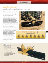
Application
The Land Pride RBT45 Series 3-Way Hydraulic Rear
Blades are built tough from the ground up for applications
ranging from landscaping, construction, snow removal,
and feedlot cleaning. This blade is also ideal for ditching,
road grading, and all-around farm use.
They are designed for Category II or III 3-Point hitch
mounting, attachment to tractors in the 70 to 125 hp
range and are Quick Hitch compatible. The blade with its
reversible cutting edge can be angled left or right up to
45
o
, the ends can be tilted up or down by as much as 15
o
,
and the whole blade can be offset to the left or right by as
much as 35". The blade can also be rotated 180
o
for
blading in reverse with same angling, tilting, and offset
capabilities. A retractable parking stand is included to
accommodate easier blade removal, storage, and
reattachment.
Available accessories includes manual or hydraulic
operated single or dual gauge wheel for good depth
control, end plates for holding material, skid shoes for
blade protection and manual angling, offset, and tilting
links for tractors with only one or two duplex outlets.
See “Specifications & Capacities” on page 26 and
“Features & Benefits” on page 27 for additional
information.
Using This Manual
•
This Operator’s Manual is designed to help familiarize
you with safety, assembly, operation, adjustments,
troubleshooting, and maintenance. Read this manual
and follow the recommendations to help ensure safe
and efficient operation.
• The information contained within this manual was
current at the time of printing. Some parts may change
slightly to assure you of the best performance.
• To order a new Operator’s or Parts Manual, contact
your authorized dealer. Manuals can also be
downloaded, free-of-charge, from our website at
www.landpride.com
Terminology
“Right” or “Left” as used in this manual is determined by
facing forward in the direction the machine will operate
while in use unless otherwise stated.
Definitions
IMPORTANT: A special point of information related
to the following topic. Land Pride’s intention is this
information must be read & noted before continuing.
Introduction

Section 1: Assembly & Set-Up
RBT4596 & RBT45108 Rear Blades 301-205M11/27/18
7
Table of Contents
Tractor Requirements
Weight & Horsepower
WARNING
!
To avoid serious injury or death:
Do not hitch implement to a tractor rated outside the
recommended horsepower range. Doing so can bend and/or
break the implement.
Tractor rating should be between 70 - 125 horsepower.
Tractors above the maximum horsepower rating must not
be used. Excessive horsepower can damage the Rear
Blade. Never hitch a Rear Blade to a track type tractor.
Track type tractors can damage equipment.
Weight
WARNING
!
To avoid serious injury or death:
Lightweight tractors with rear attached implements may need
weights added to the front to maintain steering control.
Consult your tractor Operator’s Manual to determine proper
weight requirements and maximum weight limitations.
Tractor weight must be capable of controlling the
Rear Blade under all operating conditions. An
underweight tractor is difficult to steer. Do not use tractors
that are too light. See Important Note Below.
3-Point Hitch
A 3-Point Category ll or lII hitch is required. The lower
3-Point arms of the 3-Point hitch must be stabilized to
prevent side-to-side movement. Most tractors have sway
blocks or adjustable chains for this purpose.
Hydraulic Outlets
WARNING
!
To avoid serious injury or death:
Hydraulic fluid under high pressure can penetrate the skin
and/or eyes causing a serious injury. Wear protective gloves
and safety glasses or goggles when working with hydraulic
systems. Use a piece of cardboard or wood rather than hands
when searching for leaks. A doctor familiar with this type of
injury must treat the injury within a few hours or gangrene
may result. DO NOT DELAY.
The number of required hydraulic duplex outlets at the
tractor is dependent upon how the 3-Way Rear Blade is
set-up.
• No outlets are required if the 3-Way Rear Blade is
set-up with manual links and ratchet jacks only.
• One to three duplex outlets are required if the 3-Way
Rear Blade is set-up with any one or more of the
following hydraulic cylinders; Offset Cylinder, Tilt
Cylinder and Angle Cylinder. Each cylinder will require
a duplex outlet at the tractor.
Section 1: Assembly & Set-Up
• A fourth duplex outlet is required if a gauge wheel is
purchased with a hydraulic cylinder.
A Selector Valve Kit may be purchased through your local
Land Pride dealer if your tractor does not have the
required number of duplex outlets. The selector valve
provides a way to operate 2 hydraulic cylinders through
one duplex outlet at the tractor. See “Hydraulic Selector
Valve” on page 15 for Kit Part No. and assembly
instructions.
Torque Requirements
See “Torque Values Chart” on page 29 to determine
correct torque values when tightening hardware.
Tractor Shutdown Procedure
The following are basic tractor shutdown procedures.
Follow these procedures and any additional shutdown
procedures provided in your tractor Operator’s Manual
before leaving the operator’s seat.
1. Reduce engine speed and disengage power take-off
if engaged.
2. Park tractor and implement on level, solid ground.
3. Lower implement to ground or onto non-concrete
support blocks.
4. Put tractor in park or set park brake, turn off engine,
and remove switch key to prevent unauthorized
starting.
5. Relieve all hydraulic pressure to auxiliary hydraulic
lines.
6. Wait for all components to come to a complete stop
before leaving the operator’s seat.
7. Use steps, grab-handles and anti-slip surfaces when
stepping on and off the tractor.

Section 1: Assembly & Set-Up
RBT4596 & RBT45108 Rear Blades 301-205M 11/27/18
8
Table of Contents
Rear Blade Assembly
Figure 1-1
18767
SHIPPING BLOCK
DO NOT REMOVE UNTIL AFTER ALL HYDRAULIC
CYLINDERS AND/OR RATCHET JACK AND
MANUAL LINKS HAVE BEEN INSTALLED.
Assembly & Set-Up Safety
WARNING
!
To avoid serious injury or death:
Do not remove shipping block from blade tilt housing until
after all manual links, ratchet jack, and/or hydraulic cylinders
have been installed and cylinders have been charged with oil.
DANGER
!
To avoid serious injury or death:
• Always check all blade hardware for tightness before
moving or working around the unit. Make sure moldboard
pivot and tilt retaining hardware is tightened to the correct
torque. The moldboard can fall from the its pivot mount or
tilt mount if retaining hardware is loose or missing.
• Components falling from the implement can injure a
person. Make certain all components are secured to the
implement before lifting it, and that the unit is properly
supported on the ground before removing lifting device.
Always keep feet and other extremities clear of areas where
components can fall.
Hitch, Frame & Blade
Refer to Figure 1-1:
1. Locate shipping crate on a level surface. Remove &
separate blade assemblies from shipping crate.
2. Use a lifting device to set blade pivot assembly (#8)
upright. Remove bolts (#5), lock washers (#6) & pivot
cap (#9) from blade pivot assembly (#8). Do not
remove shipping block in the blade tilt housing.
3. Carefully insert blade pivot assembly (#8) into main
frame (#2) at a 90° angle to the frame.
4. Reinstall pivot cap (#9), lock washers (#6), and
3/4"-16 x 1 3/4" GR5 hex head cap screws (#5).
Tighten hardware to secure main frame to blade pivot
assembly.
5. Remove 3/4" x 4 3/8" hitch pin (#10) and rotate jack
stand (#11) to a vertical position. Re-insert pin with
lock pin.
6. Lower unit to ground and unhook lifting device.
7. Remove front pivot shaft (#3) from front hitch
assembly (#1) by removing 1/2" bolts (#4).
8. Secure front hitch assembly (#1) to a lifting device or
attach to a tractor. Refer to “3-Point Hook-Up” on
page 9.
9. Insert main frame (#2) into front hitch (#1) as shown.
Reinstall front pivot shaft (#3) and secure with
1/2"-13 x 1 1/2" GR5 bolts (#4). Tighten the hardware
to secure front pivot shaft (#3).
10. If not already done, attach unit to tractor 3-Point
hitch. The top 3-Point hitch pin and linchpin are to be
supplied by the customer. See Figure 1-2 for
category settings.
11. Re-check all hardware for tightness. Torque all bolts
to specifications as listed in the “Torque Values
Chart” on page 29.
12. Check blade pivot bolts (#5) and blade tilt bolts (#7)
for tightness. If needed, tighten bolts to the correct
torque.

Section 1: Assembly & Set-Up
RBT4596 & RBT45108 Rear Blades 301-205M11/27/18
9
Table of Contents
3-Point & Quick Hitch Hook-Up
Figure 1-2
35108
Linchpin
Hitch Pin
QH20 Quick Hitch
Mounting Holes
Upper Holes: Cat. II With Bushings or Cat.III Without Bushings
See step 8 on this page for additional information.
Coupling Storage
Slots (Both Sides)
37298
Cat. III Lower Hitch Pin
Cat. II Lower Hitch Pin Install 1
7/16" O.D. bushings when using
Land Pride’s QH20 Quick Hitch.
Parking Stand
3-Point Hook-Up
WARNING
!
To avoid serious injury or death:
Always shut tractor down using “Tractor Shutdown
Procedure” provided in this manual before allowing anyone
including the operator to hook-up and unhook implement.
DANGER
!
To avoid serious injury or death:
• A crushing hazard exists while hooking-up and unhooking
implement. Keep people and animals away while backing-
up to implement or pulling away from implement. Do not
operate hydraulic controls while a person or animal is
directly behind the power machine or near the implement.
• Always check all blade hardware for tightness before
moving or working around the unit. Make sure moldboard
pivot and tilt retaining hardware is tightened to the correct
torque. The moldboard can fall from the its pivot mount or
tilt mount if retaining hardware is loose or missing.
Standard 3-Point Hook-Up
Refer to Figure 1-2:
A 3-Point Category II or III hitch is required. The lower
3-Point arms of the 3-Point hitch must be stabilized to
prevent side-to-side movement. Most tractors have sway
blocks or adjustable chains for this purpose.
1. Shorten or remove tractor drawbar to keep it from
interfering with the Rear Blade.
2. Remove linchpins and hitch pins from clevis
lugs.Keep for reuse.
3. Slowly back tractor up to Rear Blade while using
tractor’s 3-Point hydraulic control to align hitch holes
in lower arms with implement’s hitch pin holes.
4. Engage tractor park brake, shut tractor engine off
and remove key before dismounting from tractor or
allowing someone else to hook-up the Rear Blade.
5. With tractor’s lower hitch arms aligned and
positioned in the clevises, insert hitch pins through
the clevis lugs and lower arm hitch holes. Secure
hitch pins with linchpins.
6. Ensure lower arms are stabilized to prevent
excessive side movement.
7. Refer to Figure 1-1 on page 8: Remove hitch
pin (#10) from parking stand (#11) and rotate stand
up. Reinsert hitch pin and secure with hairpin cotter.
8. Connect Cat. II top center link to upper holes using
customer supplied 1" clevis pin & linchpin. If top
center link is Cat. III, drive 1" x 1 1/4" x 1 5/8"
bushings out and connect center link to upper holes
using customer supplied 1 1/4" clevis pin & linchpin.
9. Manually adjust one of the two lower lift arms up or
down to level the Rear Blade from left to right.
10. Manually adjust length of top-link to level Rear Blade
front to rear.
11. Check clearances after all offset, pivot, and tilt
linkages have been installed. Refer to “Inspection
After Hook-Up” on page 20.
Quick Hitch Hook-Up
Refer to Figure 1-2:
The customer must purchase and install two
1.141" ID x 1.4375" OD x 2 1/2" long busings (Land Pride
Part No. 890-940C) on the lower hitch pins. Also, the
center hitch pin must be moved to the lower hitch holes.
Follow hook-up and unhooking instructions in the Quick
Hitch Operator’s manual when using a Quick Hitch.
NOTE: Land Pride’s Quick Hitch can be attached to
the tractor to provide quick and easy 3-point hook-
up and detachment. See your nearest Land Pride
dealer to purchase a Quick-Hitch.

Section 1: Assembly & Set-Up
RBT4596 & RBT45108 Rear Blades 301-205M 11/27/18
10
Table of Contents
Blade Angling Cylinder
Refer to Figure 1-4:
WARNING
!
To avoid serious injury or death:
Do not remove shipping block from blade tilt housing until
after all manual links, ratchet jack, and/or hydraulic cylinders
have been installed and cylinders have been charged with oil.
1. Position hydraulic cylinder (#3) with ports on top as
shown. Install two 90 degree elbows (#4) into the
cylinder ports as shown. Tighten as needed.
2. Screw 74" long hydraulic hose (#6) into elbow (#4) at
the cylinder base and tighten.
3. Screw 82" long hydraulic hose (#5) into elbow (#4) at
the cylinder rod end and tighten.
4. Thread adapter fittings (#7) to the other end of the
hydraulic hoses and tighten. (Customer to supply
quick disconnect hydraulic couplings.)
5. Attach hydraulic cylinder to the lugs on the right side
of the frame with clevis pins (#1). Make sure
hydraulic ports are positioned on top and the cylinder
base in positioned to the front as shown.
6. Secure clevis pins with hair pin cotters (#2).
7. Route hoses through hose bracket located on the
right side of the front hitch. Connect hoses to tractor's
hydraulic system.
Hydraulic Blade Angling
Figure 1-4
IMPORTANT: Attach cylinder base to the front
cylinder mount. The base will interfere with the
mainframe if attached to rear cylinder mount.
24994
Customer to supply Quick Disconnect Couplings.
Blade Offset Cylinder
Refer to Figure 1-3:
WARNING
!
To avoid serious injury or death:
Do not remove shipping block from blade tilt housing until
after all manual links, ratchet jack, and/or hydraulic cylinders
have been installed and cylinders have been charged with oil.
Assemble hydraulic hoses to the hydraulic cylinder
before placing cylinder on the blade.
1. Position hydraulic cylinder (#3) with ports on top as
shown. Install two 90 degree elbows (#4) into the
cylinder ports as shown. Tighten as needed.
2. Screw 74" long hydraulic hose (#6) into elbow (#4) at
the cylinder base and tighten.
3. Screw 82" long hydraulic hose (#5) into elbow (#4)
located at the cylinder rod end and tighten.
4. Thread adapter fittings (#7) to the other end of the
hydraulic hoses and tighten. (Customer to supply
quick disconnect hydraulic couplings.)
5. Attach hydraulic cylinder to lugs located on left side of
3-Way Rear Blade with clevis pins (#2). Make sure
hydraulic ports are positioned on top and the cylinder
base in positioned to the front as shown.
6. Secure clevis pins with hair pin cotters (#1).
7. Route hoses through hose bracket located on the
right side of the front hitch. Connect hoses to tractor's
hydraulic system.
Hydraulic Blade Offsetting
Figure 1-3
IMPORTANT: Attach cylinder base to the front
cylinder mount. The base will interfere with the
mainframe if attached to rear cylinder mount.
24993
Customer to supply Quick Disconnect Couplings.

Section 1: Assembly & Set-Up
RBT4596 & RBT45108 Rear Blades 301-205M11/27/18
11
Table of Contents
Blade Tilting Cylinder
Refer to Figure 1-5:
WARNING
!
To avoid serious injury or death:
• Do not remove shipping block from blade tilt housing until
after all manual links, ratchet jack, and/or hydraulic
cylinders have been installed and cylinders have been
charged with oil.
• The Rear Blade may be unstable and hard to control until
all the hydraulic cylinders have been purged with oil.
IMPORTANT: The blade tilt cylinder receives a 90
degree elbow with a small orifice in one end of the
elbow. Make sure this orifice elbow is installed in the
cylinder port at the rod end of the tilt cylinder.
IMPORTANT: Attach cylinder base to the upper
cylinder mount. The base will interfere with the
moldboard if attached to the lower cylinder mount.
Hydraulic Blade Offsetting and Angling
Figure 1-5
24995
SHIPPING BLOCK
DO NOT REMOVE UNTIL AFTER ALL HYDRAULIC
CYLINDERS, RATCHET JACKS AND/OR MANUAL
LINKS HAVE BEEN INSTALLED.
Customer to supply Quick
Disconnect Couplings (#8).
1. Install a 90 degree elbow (#5) with 3/32" orifice (#4)
into the cylinder port located at the rod end as shown.
Tighten as needed.
2. Install a second 90 degree elbow (#6) without an
orifice into the cylinder port located at the base
shown. Tighten as needed.
3. Screw 111" long hydraulic hoses (#7) into
elbows (#5 & #6) and tighten.
4. Thread adapter fittings (#8) to the other end of the
hydraulic hoses and tighten. (Customer to supply
quick disconnect hydraulic couplings.)
5. Attach hydraulic cylinder (#3) to the lugs at the back
of the blade with clevis pins (#2). Make sure hydraulic
ports are positioned on the back and the cylinder
base is mounted to the center lug as shown.
6. Secure clevis pins with hair pin cotters (#1).
7. Route hoses through hose brackets located on the
main frame and hitch. Connect hoses to tractor's
hydraulic system.
8. Remove shipping block at this time.

Section 2: Set-Up of Accessories
RBT4596 & RBT45108 Rear Blades 301-205M 11/27/18
12
Table of Contents
Manual Offset, Angling and Tilt
Figure 2-1
24999
Blade Angling
Blade Offset
Blade Tilting
SHIPPING BLOCK
DO NOT REMOVE UNTIL AFTER ALL
HYDRAULIC CYLINDERS AND/OR
RATCHET JACK AND MANUAL LINKS
HAVE BEEN INSTALLED.
Section 2: Set-Up of Accessories
Manual Offset, Angling and Tilting
Kit Bundles
300-206A. . . . . . MANANUAL ANGLE LINK ASSEMBLY
300-206A. . . . . MANANUAL OFFSET LINK ASSEMBLY
890-637C . . . . . . . . . . . RATCHET JACK 16.25 - 22.25
The manual links and ratchet jack may be used in place
of the hydraulic cylinders.
WARNING
!
To avoid serious injury or death:
Do not remove shipping block from blade tilt housing until
after all manual links, ratchet jack, and/or hydraulic cylinders
have been installed and cylinders have been charged with oil.
Blade Angling Manual Link
Refer to Figure 2-1:
1. Attach manual angling links (#3 & #4) to the right side
of the Rear Blade as shown with two 1" clevis
pins (#1). Secure with hair pin cotters (#5).
2. Adjust blade angle by removing hitch pin (#2) and
moving outer link (#3) to a different hole. Replace
hitch pin and secure with hair pin cotter (#5).
Blade Offset Manual Link
Refer to Figure 2-1:
1. Attach manual offset links (#3 & #4) to the left side
of the Rear Blade as shown with two 1" clevis
pins (#1). Secure with hair pin cotters (#5).
2. Adjust offset angle by removing hitch pin (#2) and
moving outer link (#3) to a different hole. Replace
hitch pin and secure with hair pin cotter (#5).
Blade Tilting Ratchet Jack
Refer to Figure 2-1:
1. Attach ratchet jack (#6) to the back side of the Rear
Blade as shown with two 1" clevis pins (#1). Secure
with hair pin cotters (#5).
2. Adjust blade tilt by setting the lock on the ratchet
lever and pumping the lever back and forth to raise
one end of the blade higher than the other end.
Reposition ratchet lock and pump lever back and
forth to tilt blade in the opposite direction.
3. Remove shipping block after ratchet jack (#6) has
been installed.

Section 2: Set-Up of Accessories
RBT4596 & RBT45108 Rear Blades 301-205M11/27/18
13
Table of Contents
Hydraulically Controlled Gauge Wheel
Figure 2-2
24996
Customer to supply Quick
Disconnect Couplings.
Ratchet Jack Set-Up
1. Attach ratchet jack (#19) to the mounting lugs on the
gauge wheel arm (#3) and mounting bracket (#11)
with two 1" clevis pins (#20). Secure pins with hair pin
cotters (#21).
Hydraulic Cylinder Set-Up
1. Position hydraulic cylinder (#15) with ports on top as
shown. Thread 90 degree elbows (#13) into the two
ports and tighten.
2. Screw 116" long hydraulic hoses (#14) to the elbows
and tighten.
3. Thread hydraulic couplings (#18) to the other end of
hydraulic hoses and tighten. (Customer to supply
quick disconnect hydraulic couplings.)
4. Attach hydraulic cylinder to the lugs on the gauge
wheel with two 1" clevis pins (#17). Make sure
hydraulic ports are positioned on top and cylinder
base is located to the front as shown.
5. Secure clevis pins with hair pin cotters (#16).
6. Route hoses through the hose brackets located on
the top of the main frame and right side of the front
hitch. Connect hoses to tractor's hydraulic system.
IMPORTANT: Attach cylinder base to the front
mounting lug. The base will interfere with the gauge
wheel arm if attached to the rear mounting lug.
Gauge Wheel
Kit Bundles
301-225A. . . . . . HYDRAULIC SINGLE GAUGE WHEEL
301-236A. . . . . . . .HYDRAULIC DUAL GAUGE WHEEL
301-281A. . . . . . . . .MANUAL SINGLE GAUGE WHEEL
301-282A. . . . . . . . . . MANUAL DUAL GAUGE WHEEL
Refer to Figure 2-2::
1. Attach gauge wheel mounting bracket (#11) to Rear
Blade frame with two 3/4"-10 x 10 1/2" GR5 hex head
bolts (#8) and 3/4" hex nuts (#10). Tighten nuts to
correct torque.
2. Insert gauge wheel hitch tube (#9) in gauge wheel
arm (#3).
3. Attach gauge wheel arm (#3) to mounting
bracket (#11) with 3/4"-10 x 10 1/2" GR5 hex head
bolt (#8) and 3/4" hex nut (#10). Tighten nut to correct
torque.
4. Insert gauge wheel caster assembly (single wheel
caster #1) or (dual wheel caster #2) in gauge wheel
arm (#3) and retainer washer (#4). Secure caster
assembly with 1/2" x 2 1/2" long roll pin (#5).
5. Attach center floating link (#12) to the front hitch with
1 1/4" x 1 3/4" hitch pin (#7). Secure with hair pin
cotter (#6).

Section 2: Set-Up of Accessories
RBT4596 & RBT45108 Rear Blades 301-205M 11/27/18
14
Table of Contents
Hydraulic Cushion Valve Assembly
Figure 2-3
24997
Customer to supply Quick
Disconnect Couplings.
Blade Ange Cylinder
Blade Offset Cylinder
Hydraulic Cushion Valve
Kit Bundles
301-235A . . . . . . . . . 96" - CYLINDER CUSHION VALVE
301-234A . . . . . . . . 108" - CYLINDER CUSHION VALVE
CAUTION
!
To avoid minor or moderate injury:
Do not operate Rear Blade with angling or offset cylinder fully
extended. Fully extending either cylinder will keep cushion
valves from operating correctly.
Refer to Figure 2-3:
1. Mount cushion valves (#1 & #2) onto mounting plate
with 3/8"-16 x 4" GR5 hex head cap screws (#3),
spring lock washers (#4) and hex nuts (#5). Tighten
hex nuts to correct torque.
2. Screw eight fittings (#6) into cushion valves (#1 & #2)
until tight.
3. Attach hydraulic hose (#7) to the right rear fitting of
cushion valve (#2) as shown.
4. Attach hydraulic hose (#8) to the right front fitting of
cushion valve (#1) as shown.
5. Attach hydraulic hose (#9) to the left rear fitting of
cushion valve (#1) as shown.
6. Attach hydraulic hose (#10) to the left front fitting of
cushion valve (#2) as shown.
7. Attach four hydraulic hoses (#11) included with this
option to the remaining cushion valve fittings (#6) and
thread through the hose retainer (#12).

Section 2: Set-Up of Accessories
RBT4596 & RBT45108 Rear Blades 301-205M11/27/18
15
Table of Contents
Hydraulic Selector Valve
Kit Bundle
301-227A . . . . . . . . . . Double Selector Valve Assembly
Refer to Figure 2-4:
An optional hydraulic selector valve kit may be purchased
that bolts to the front hitch frame. This kit provides a way
to operate 2 cylinders at one outlet, thereby reducing the
number of required outlets at the tractor by one. See also
“Tractor Requirements” on page 7.
1. Remove existing two bolts (#4) and discard.
2. Attach selector mount (#9) to the top of the hitch with
two new 1/2"-13 x 2" GR5 hex head cap screws (#4),
flat washers (#5), spring lock washers (#6), and hex
nuts (#7). Tighten nuts to the correct torque.
3. Attach double selector valve (#3) to selector
mount (#9) with two 3/8"-16 x 3" GR5 hex head cap
screws (#8), spring lock washers (#10), and hex
nuts (#11). Tighten nuts to the correct torque.
Hydraulic Selector Valve Assembly
Figure 2-4
24998
Customer to supply Quick
Disconnect Couplings.
4. Apply teflon tape to the pipe threads of the three
3/4 x 1/2MNPT elbows (#1) and screw them into the
double selector valve as shown. Tighten to correct
orientation.
5. Apply teflon tape to the threads of the three
3/4JIC x 1/2MNPT adapters (#13) and screw them
into the double selector valve until tight.
6. Attach three 3/4JIC x 3/4JIC elbows (#12) to the
adapters (#13). Tighten to correct orientation.
7. Attach blade offset hydraulic hoses (#14) to the
bottom elbows.
8. Attach hydraulic hoses (#15) from one of the other
cylinders to the top elbows.
9. Attach tractor connected hydraulic hoses (#2) to the
side elbows.
10. Thread hydraulic adapters onto hydraulic hoses (#2)
and tighten. (Customer to supply quick disconnect
hydraulic couplings.)

Section 2: Set-Up of Accessories
RBT4596 & RBT45108 Rear Blades 301-205M 11/27/18
16
Table of Contents
Skid Shoe
Kit Bundle (Pair of skid shoes)
301-333A. . . . . . . . . . . . . . . . . SKID SHOE ASSEMBLY
Refer to Figure 2-5:
The skid shoes are attached to both ends of the blade to
help prevent damage to the surface of the ground by the
blade.
1. Remove two 5/8"-11 x 1 3/4" GR5 plow bolts (#1)
from the end of the blade. Keep hardware for
installation of skid shoes.
2. Attach skid shoe bracket (#3) with 5/8"-11 x 1 3/4"
GR5 plow bolts (#1), flat washers (#2), and hex
flange locknuts (#4). Tighten hardware to the correct
torque.
3. Insert skid shoe (#5) into skid shoe bracket (#3).
Secure with bent pin (#6) and hairpin cotter (#7).
4. Repeat steps 1 through 3 for the other side.
Skid Shoe Assembly
Figure 2-5
25535
End Plates
Kit Bundle (Pair of End Plates)
301-147A. . . . . . . . . . . . . . . . . . . . . . . . . .END PLATES
Refer to Figure 2-6:
End plates are attached to both ends of the blade,
eliminating spillage when moving snow or loose material.
1. Attach right-hand end plate (#3) to the moldboard as
shown with two 5/8"-11 x 2" GR5 hex head cap
screws (#4), spring lock washer (#7), and hex nuts
(#8). Draw hex nuts up snug. Do not tighten.
2. Attach side plate support strap (#2) with two
1/2"-13 x 1 1/4" GR5 hex head cap screws (#1), lock
washers (#5), and hex nuts (#6). Draw hex nuts up
snug. Do not tighten
3. First tighten hex nuts (#8) to the correct torque and
then next nuts (#6) last.
4. Repeat steps 1 through 3 for the left-hand end plate.
.
End Plate Assembly
Figure 2-6
NOTE: Alternate tightening of bolts when installing
mounting hardware. Some deflection may occur in
moldboard.
12550
/