Page is loading ...

Size rounded off to the nearest foot
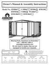
Model No.
Exterior Dimensions
(Lid Edge to Lid Edge)
Width Depth Height
Interior Dimensions
(Wall to Wall)
Width Depth Height
Door
Opening
Width Height
Approx.
Size
Storage
Area
6’ x 3’ 15 Sq. Ft. 44 Cu. Ft. 67” 36 1/4” 36 1/4” 65 1/2” 33” 35” 31 7/8 32 3/8”
1,7 m x 0,8 m 1,4 m2 1,2 m3170,2 cm 92,1 cm 92,1 cm 166,4 cm 83,8 cm 88,9 cm 81,0 cm 82,2 cm
BUILDING DIMENSIONS
6’ x 3’
Nominal Size
Gloves must be worn
at all times to reduce
risk of injury!
* See Inside for Detailed Safety Information.
Owner’s Manual
& Assembly Guide
01DF
717571216
†
†
Base
Size
68 1/4” x 35 3/4”
173,4 cm x 90,8 cm
www.arrowsheds.com
Customer Service:
1-800-851-1085 or
NG63
NB63 NB63EU
AA A

GB: Assembly manual in additional languages available online.
Scan QR code below to access.
FR: Manuel de montage disponible en ligne dans d’autres langues.
Pour y accéder, scannez le code QR ci-dessous.
SP: Manual de montaje en idiomas adicionales disponible online.
Escanee el código QR a continuación para acceder.
DE: Montageanleitung in zusätzlichen Sprachen online verfügbar.
Scannen Sie den QR-Code unten, um darauf zuzugreifen.
I T: Manuale dell’assemblea in altre lingue disponibile online.
Per accedere effettua la scansione del codice QR in basso.
P T: Manual de montagem disponível em outros idiomas online.
Digitalize o código QR abaixo para obter acesso.
D T: Samlingshåndbog i yderligere sprog til rådighed online.
Scan QR kode nedenunder for at få adgang.
SK:Nainternetejekdispozíciinávodnazostavenievďalšíchjazykoch.
Dostanete sa k nemu naskenovaním kódu QR.
CZ:Návodkmontáživdalšíchjazycíchjekdispozicivonlineverzi.
PřístupzískáteponaskenováníQRkóduníže.
HU: Azösszeszerelésiútmutatótovábbinyelvekeniselérhetőonline.
A hozzáféréshez olvassa be az alábbi QR-kódot.
GR: Υπάρχειδιαθέσιμοστοδιαδίκτυοτοεγχειρίδιοσυναρμολόγησης
σεπερισσότερεςγλώσσες.Σαρώστετονπαρακάτωκώδικα
QRγιανααποκτήσετεπρόσβαση.
P/N 6PP722621216

2
BEFORE YOU BEGIN...
Safety precautions MUST be followed at all times throughout the construction of your Storage Unit!
•Care must be taken when handling various pieces of your Storage Unit since
many contain sharp edges. Please wear work gloves, eye protection and long
sleeves when assembling or performing any maintenance on your Storage
Unit.
•Practice caution with the tools being used in the assembly of your Storage
Unit. Be especially familiar with the operation of all power tools.
•Keep children and pets away from the worksite during construction. Do not
allow children to help with assembly.
•Do NOT attempt to assemble your Storage Unit on a windy day. The large
panels can catch the wind like a “sail”, causing them to be whipped around
making construction diffi cult and unsafe.
•We recommend two people work together to assemble your Storage Unit.
This will make assembly faster and easier.
•Your Storage Unit needs to be anchored after assembly. The Storage Unit
may be anchored to a deck or concrete patio using deck screws or concrete
anchors. You may also anchor it to any fl at, level surface. Alternatively, patio
blocks may be used to anchor the Storage Unit. See back page for more info.
02D
• Work Gloves
• Safety Glasses
• No. 2 Phillips Screwdriver (Magnetic Tip Preferred)
• Pliers
• Power Drill (Cordless, Variable Speed)
• Nut Driver or Wrench
• Awl (to align holes)
WHAT YOU NEED
RECOMMENDED TIME SAVERS
Reading and following all steps carefully will help make assembly quicker and easier. Before you begin
assembly, be sure to confi rm that all the parts for your Storage Unit are present using the checklist on
pages 3 and 4. If parts are missing or damaged, include the model number of your Storage Unit and
contact Customer Service at 1-800-851-1085 or online at [email protected].
Below is a list of things you will need to assemble your Storage Unit.
NOT RECOMMENDED FOR STORAGE OF CORROSIVE CHEMICALS OR PRODUCTS

3
HARDWARE LIST...
Part Numbers
Part Number
1. Each part has an identifying part number on it.
2. Part Numbers are referenced in each step.
3. Unpainted parts have a stamped in number and painted
parts have a number that is inked on.
Remove inked on numbers with soap and water after assembly.
Key Part Part Qty.
No. No. Description List
56
10
11
12
34
8
9
13 14
7
12
11/32 Hex.
#2 Phillips
#2 Phillips #2 Phillips
03D
1 65103 Hex Nut (#8-32) 74
2 65923 Bolt (#8-32 x 3/8) (10 mm) 71
3 65958 Long Bolt (#8-32 x 7/8) (22 mm) 1
4 65004 Screw (#8AB x 5/16) (8 mm) 68
5 65900A Black Screw (#10B x 1/2) (13 mm) 8
6 66646 Washer Sheet 3
7 6481 Gusset 2
8 66045 Door Handle 2
9 66769 Door Slide 4
10 66382 Door Guide 4
11 66609 Hinge 3
12 10670 Lid Latch Bracket 1
13 7022 Eave Bracket 1
14 10672 Door Latch Finger 1
15 66776 Foam Tape 1
16 65109 Acorn Nut 2
#2 Phillips
15 16
5/16 Hex.
Confi rm that all hardware and parts are present
before attempting to assemble your Storage Unit.
Customer Service:
1-800-851-1085 or
For missing or damaged parts, contact Customer
Service. Do not return to store.

6
PARTS LIST...
4
Key Part Part Qty.
No. No. Description List Selected End Views by Key No.
14
Unpainted
13
Unpainted
12
22
Unpainted
Painted
15
Unpainted
17-20
Unpainted
21
Unpainted
1110
Unpainted
9
8
Unpainted
7
Painted
1
Painted
04D
1 10499 Horizontal Door Brace 4
2 9747 Rear Wall Panel 2
3 9748 Rear Corner Panel 2
4 9749 Front Corner Panel 2
5 10674 Right Lid Panel 1
6 9751 Lid End Panel 2
7 9752 Rear Floor Frame 1
8 9753 Side Floor Frame 2
9 9754 Front Floor Frame 1
10 9755 Door Track Angle 1
11 9756 Door Track 1
12 9757 Rear Wall Angle 1
13 9758 Right Top Channel 1
14 9759 Left Top Channel 1
15 9760 Door Jamb 2
16 10676 Right Door 1
17 9763 Lid Front Channel 1
18 9764 Lid Rear Channel 1
19 9765 Lid Left Channel 1
20 9766 Lid Right Channel 1
21 9767 Lid Support Arm 1
22 9768 Lid Diagonal Brace 2
23 80047 Left Lid Panel 1
24 80049 Left Door 1
Unpainted
Whenever a crimped rib and an uncrimped
rib meet, the crimped rib should be placed
UNDER the uncrimped rib if possible.
Crimped Rib
Uncrimped Rib
Some Tips for Assembly:
Painted

ASSEMBLY BY KEY NO.
5
05D
1
1
1
1
2
2
3
3
4
4
5
23
6
6
7
8
8
9
10
11
12
13
14
15
15
16
24
17
18
19
20
21 22
22

6
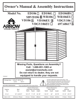
Step 1
9754
9755
ANCHORING HOLES
6
06D
You will need for this page:
(QTY: 13)
• 9755 Door Track Angle (1)
• 9754 Front Floor Frame (1)
• 9752 Rear Floor Frame (1)
• 9753 Side Floor Frame (2)
• 6481 Gusset (2)
Use Bolts and Nuts to attach the Lower Door Track Angle to the Front Floor Frame as shown.
Double check that the end view of the
assembled frame looks like the image to
the right.
1
2
TO FRONT
FRONT
REAR
Assemble Floor Frame as shown using Bolts and Nuts.
9752
6481
6481
9753
9753

7
07D
You will need for this page:
(QTY: 22)
• 9747 Rear Wall Panel (2)
• 9748 Rear Corner Panel (2)
• 9749 Front Corner Panel (2)
Panels overlap as shown to the left. Start
at one corner and work around the building
when attaching Panels.
Position Panels as shown and secure
to the Floor Frame with Screws.
Fasten Screws thru all holes in the bottom
of the Panels except at Rib Overlaps and
the holes closest to the Door opening. Use
a Bolt and Nut to fasten Panels together at
Rib Overlaps as shown.
3
Place Washers on all Bolts and
Screws used on painted parts.
DO NOT FASTEN AT THIS TIME
(QTY: 10)
9747
9747
9748
9748
9749
9749

6
Step 2
Attach the Rear Wall Angle, Hinges, and Lid
Rear Channel together using Bolts and Nuts as
shown. Double check that the end view of the
assembled piece matches the image above.
8
08D
You will need for this page:
(QTY: 10) (QTY: 18)
• 9757 Rear Wall Angle (1)
• 9764 Lid Rear Channel (1)
• 66609 Hinge (3)
• 9756 Door Track (1)
• 66769 Door Slide (4)
• 9760 Door Jamb (2)
9764
9757
9756
Slide ALL Door Slides into the Door Track before installation.
Attach the Rear Wall Angle Assembly to the
Walls with Bolts and Nuts and Door Track to
the Walls with Screws as shown.
Next, attach the Door Jambs to the Walls and
Door Track as shown.
Long leg on top.
4
3
1
2
Wall Panel
TO REAR
Bolt must go thru back side of Panel
or it may interfere with Door action.
(QTY: 10)
(QTY: 2)
66769
66609 66609 66609
9760
9760
Hint: Attach fasteners in
order shown in diagram.
312
312
312
312312

Next, secure the Left and Right Top Channels to the Front and Rear of the
9
09D
You will need for this page:
(QTY: 24) (QTY: 4) (QTY: 4)
• 9758 Right Top Channel (1)
• 9759 Left Top Channel (1)
• 10674 Right Lid Panel (1)
• 80047 Left Lid Panel (1)
• 9751 Lid End Panel (2)
• 9763 Lid Front Channel (1)
Position the Left and Right Top Channels as shown and secure to Walls with Screws.
building with Screws in Front and Bolts and Nuts in Rear as shown.
Slide ALL Lid Panels into the Lid Rear
Channel and secure with Screws as
shown. Do not fully tighten.
Next, position the Lid Front Channel
and secure with Screws as shown. Do
not fully tighten at this time.
Notched side of Frame faces INSIDE building.
5
6
7
8
9758
9759
10674
80047
9751
9751
9763
Holes in Panels MUST be in Front and Center of Unit.

6
Step 3
10
10D
You will need for this page:
• 9765 Lid Left Channel (1)
• 9766 Lid Right Channel (1)
• 7022 Eave Bracket (1)
Attach the Eave Bracket to the Lid Left Channel with Bolts and Nuts as shown.
1
Bend the tabs on both ends
of the Lid Left and Right
Channels as shown.
2
Slide the Lid Left and Right Channels into place as shown below.
Fasten to Lid Front and Rear Channels with Screws. Parts should
overlap as shown to the right.
3
The end view of the assembled
Channel should match the image
to the left.
(QTY: 4) (QTY: 2)
7022
9765
9765
9766

9768
9768
11
11D
You will need for this page:
(QTY: 4)
• 9768 Lid Diagonal Brace (2)
• 9767 Lid Support Arm (1)
Notch in Lid Support Arm MUST face rear of Unit.
Working with one Brace at a time, attach
each Diagonal Brace to the bottom of the
Lid at the ends and then rotate to align with the
top of the Lid. With both Braces in place, secure
the Braces in the middle with a Long Bolt and
Nut as shown. Fully tighten all Screws and Bolts,
including Screws from previous step.
4
When inserting the Long
Bolt in the Diagonal Braces,
fi rst locate the Nut against the back side
of the hole with your fi nger and thread
the Bolt into the Nut. This will make the
process easier.
Place a Bolt thru the bottom of the Lid Support Arm as
shown. There should be a Nut on BOTH sides of the
Support Arm as indicated.
5
Now slide the Support Arm up thru the slot in the Left Top Channel as shown.
6
(QTY: 1)
9767
(QTY: 1)
After alligning each Brace with the hole in the bottom of the Lid, you
must close the Lid before you can access the hole and insert the Screw.

6
Step 4
12
12D
• 66776 Foam Tape (1)
Next, rotate the Lid Support Arm into place and
attach to the Eave Bracket with a Bolt and two Nuts
as shown. Tighten the second Nut against the fi rst.
The second Nut will act as a ‘Jam Nut’ keeping the
fi rst Nut in place.
1
With the Lid assembled, apply the
foam weather stripping tape to
the outer edge of the Unit as shown.
There should be no gaps in the tape
except where the Lid Support Arm Slot
is located. Press fi rmly as you apply to
ensure good adhesion.
2
66776
Be sure to leave a gap
as indicated in the
image above when installing the Lid
Support Arm. This gap will allow
the Lid Support Arm to pivot as the
Lid is closed. If you do not leave a
gap the Lid may close improperly.
You will need for this page:
(QTY: 1)

13
13D
You will need for this page:
10670
Next, attach the Lid Latch Bracket to the Lid
with Bolts and Nuts as shown. Double check
that the Bracket is positioned as shown.
3
(QTY: 2)
• 10670 Lid Latch Bracket (1)

6
Step 5
You will need for this page:
(QTY: 4)
(QTY: 4) (QTY: 8)
• 10676 Right Door (1)
• 80049 Left Door (1)
• 10499 Horizontal Door Brace (4)
• 10672 Door Latch Finger (1)
• 66045 Door Handle (2)
• 66382 Door Guide (4)
14
14D
Do NOT place hardware thru the top row of holes
yet. These lines are to show alignment only.
Attach the Door Handles to the Left and Right
Doors with Bolts and Nuts as shown. Attach the
Door Guides and the Horizontal Door Braces to
the BOTTOM side of the Left and Right Doors using
Bolts and Nuts as shown.
Next, place one Door in the Front Bottom Frame
and rotate it into place as shown above. Position
the Horizontal Door Brace (and Door Latch
Finger for the Left Door) as shown (see next page)
and secure to Door Slides with Black Screws.
Repeat for other Door.
Each Door Slide has three sets of holes. Install Doors
by placing the Black Screws thru the middle holes
fi rst. If Doors do not align, raise or lower the Doors by
moving the Screws to a different set of holes. Middle Holes
1
2
10676
80049
80049
10676
10499
10499
10499
10499
10672
66045
66045
66382
66382
66382
66382

15
15D
The Lower Door Guide should be positioned
on the Door as shown above.
LID LATCHED
With the Lid Latch in place, CLOSING the Doors will LATCH
the Lid and OPENING the Doors will UNLATCH the Lid.
DOOR OPEN
The Latch and Latch Finger should interlock
as shown when the Left Door is closed. If
they do not align, loosen the Bolts securing
them and slide to align.
LID UNLATCHED
DOOR CLOSED
INSIDE VIEW OF UNIT
80049
10676

16D
The entire fl oor frame MUST be securely anchored once the building is erected.
Here are recommended ways of anchoring.
Anchoring Your Storage Unit
Anchoring into Concrete:
1. For poured concrete slab or footing or patio blocks:
Use 1/4" x 2" (6 mm x 51 mm) Lag Screws.
2. For Anchor Post of Concrete poured after building is
erected: Use 1/4" x 6" (6 mm x 152 mm) Lag Screws.
Anchoring into Wood/Post:
Use 1/4" (6 mm) Wood Screws. There are 1/4" (6 mm)
dia. holes provided in the frames for proper anchoring.
1. 2. 1. 2.
Exterior Care:
For a long lasting fi nish clean and wax the exterior surface. We recommend washing with a mild soap solution. DO
NOT use power washing to clean your Storage Unit. Using a spray automotive type wax periodically on the exterior
is highly recommended if you are in a high humidity or coastal climate region.
Combustibles and corrosives must be stored in air tight containers designed for chemical and/or combustible
storage. Corrosive chemicals such as fertilizers, pesticides and herbicides should be cleaned off the interior and
exterior surfaces immediately. Rust caused by chemical damage is not covered by the warranty.
DO NOT STORE POOL CHEMICALS IN YOUR STORAGE UNIT - THIS VOIDS YOUR WARRANTY
Rust protection precautions may help to stop rust from developing, or stop it quickly as soon as it appears.
• Avoid nicking or scraping the coating surface, inside and out.
• Use washers everywhere indicated in this manual to help prevent corrosion.
• Keep lid, base perimeter and door tracks free of debris and leaves which may accumulate and retain moisture.
These can do double damage since they give off acid as they decay. Lubricate door track as needed.
• Touch up scrapes or nicks and any area of visible rust as soon as possible. Make sure the surface is free of
moisture, oils, dirt or grime and then apply an even fi lm of high quality touch-up paint.
• Various paint manufacturers provide products for rust treatment and coverage. If surface rust does appear on your
Storage Unit we recommend treating those areas as soon as possible, following the paint supplier of your choice
instructions.
Please note, Manufacturer cannot be held responsible for any consequences due to buildings that are not installed
per these instructions, or for damage due to weather conditions or acts of God.
Keep these assembly instructions and owner’s manual for future reference.
16

ASSEMBLY NOTES
46A
17

ASSEMBLY NOTES
46A
18

/