Page is loading ...

©2007 Johnson Level & Tool
1
Self-Leveling Rotary Laser Level
Model Nos. 40-6515 and 40-6516
Instruction Manual
Congratulations on your choice of this Self-Leveling Rotary Laser
Level. We suggest you read this instruction manual thoroughly before
using the instrument. Save this instruction manual for future use.
This is a Class IIIa laser tool and is manufactured to comply
with CFR 21, parts 1040.10 and 1040.11 as well as international
safety rule IEC 285.
™

2
©2007 Johnson Level & Tool
Table of Contents
1. Kit Contents
2. Features and Functions
3. Safety Instructions
4. Location/Content
of Warning Labels
5. Location of Parts/Components
6. Operating Instructions
7. Using the Product
8. Self-Check and Calibration
9. Technical Specifications
10. Application Demonstrations
11. Care and Handling
12. Product Warranty
13. Product Registration
14. Accessories
1. Kit Contents
For Model No. 40-6515
Description Qty.
Self- Leveling Rotary Laser Level 1
“AA” Alkaline Batteries 4
Tinted Glasses 1
Instruction Manual with Warranty Card 1
Soft Sided Carrying Case 1
For Model No. 40-6516
Description Qty.
Self- Leveling Rotary Laser Level 1
“AA” Alkaline Batteries 4
Tinted Glasses 1
Detector with 9V Battery and Quick Clamp 1
Instruction Manual with Warranty Card 1
Hard Shell Carrying Case 1

©2007 Johnson Level & Tool
3
2. Features and Functions
• Magnetic dampening compensation system.
• If laser is out of its self-leveling range, rotation stops and alarm
sounds.
• Projects a horizontal laser plane.
• Projects a vertical laser plane with 90° split beam reference.
• Laser rotation speed is 200, 400, 600 RPM.
• Water and dust resistant.
3. Safety Instructions
Please read and understand all of the following instructions, prior
to using this tool.
CAUTION: If using this product with any type of tinted goggles,
please note safety warning below.
DANGER!
Class IIIa Laser Product
Max. Power Output: ≤5mW
Wavelength: 625-645nm
THIS TOOL EMITS LASER RADIATION.
DO NOT STARE INTO BEAM.
AVOID DIRECT EYE EXPOSURE.

4
©2007 Johnson Level & Tool
WARNING!
The tinted goggles are designed to enhance
the visibility of the laser beam. They DO NOT
offer protection to the eyes from direct exposure
of the laser beam.
ATTENTION IMPORTANT
• Read all instructions prior to operating this laser tool. Do not remove any labels from
tool.
• Do not stare directly at the laser beam.
• Do not project the laser beam directly into the eyes of others.
• Do not set up laser tool at eye level or operate the tool near a reflective surface as
the laser beam could be projected into your eyes or into the eyes of others.
• Do not place the laser tool in a manner that may cause someone to unintentionally
look into the laser beam. Serious eye injury may result.
• Do not operate the tool in explosive environments, i.e. in the presence of gases or
flammable liquids.
• Keep the laser tool out of the reach of children and other untrained persons.
• Do not attempt to view the laser beam through optical tools such as telescopes as
serious eye injury may result.
• Always turn the laser tool off when not in use or left unattended for a period of time.
• Remove the batteries when storing the tool for an extended time (more than 3 months)
to avoid damage to the tool should the batteries deteriorate.
• Do not attempt to repair or disassemble the laser tool. If unqualified persons attempt
to repair this tool, warranty will be void.
• Use only original AccuLine Pro™parts and accessories purchased from your AccuLine
Pro authorized dealer. Use of non-AccuLine Pro parts and accessories will void warranty.

©2007 Johnson Level & Tool
5
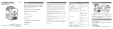
4. Location/Content of Warning Labels

6
©2007 Johnson Level & Tool
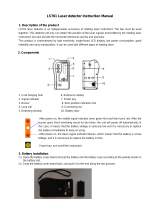
5. Location of Part/Components
Rotating Laser
Output Widow
Keypad
Lock Knob –
Compensator/
Transportation
Battery Door
DC 6V Outlet
(6V Adapter not
included)
5/8” – 11 Screw
Thread
90° Split Beam Laser
Output Window
Vertical Vial
Charging LED
Vertical Vial Adjustment
Knob

©2007 Johnson Level & Tool
7
6. Operating Instructions
IMPORTANT: It is the responsibility of the user to verify the
calibration of the instrument before each use.
Alkaline Battery Installation
Note: Always check to be sure that the on/off switch is in the off
position before removing and replacing batteries.
1. Install alkaline batteries into the battery case according to the
polarity illustrated in the battery compartment.
2. Snap the battery door back and tighten the screw.
Ni-MH Rechargeable Battery Installation (not included)
1. Put the battery pack into the battery case and insert the battery
plug.
2. Snap the battery door back and tighten the screw.

8
©2007 Johnson Level & Tool
Note:
• For the first two charges of new rechargeable battery pack (not
included), it is necessary to charge for 12-plus hours.
• The instrument can still work even if it is being charged with
adapter.
• Do not charge alkaline batteries to avoid explosion.
• Used (discharged) batteries are hazardous waste and should be
disposed of properly.
Bubble Adjustment While in Use Vertically
1. Turn the lock knob counter-clockwise to ‘LOCK’ the compensator.
The laser is now operating in a “manual mode” and is not
self-leveling.
2. Turn the vertical adjustment knob to make the bubble centered in
the vertical vial.

©2007 Johnson Level & Tool
9
7. Using the Product
Keypad
Before pressing the Power key, the compensator/transportation
lock knob must be turned to the “On” position.
Power Key: Press this key to power on/off the instrument.
Power LED: Lighted LED mean power-on
Extinguished LED means power-off
Flashing LED means weak battery voltage
Rotating speed switch key
Note: When starting the unit, the instrument will be in the high-speed
rotating status. While switching the rotating speed, the corresponding
LED will light up.
Rotating speed
switch key Power Key
Low speed LED
Middle speed LED
High speed LED
Power LED
600
High speed
400
Middle speed
200
Low speed

10
©2007 Johnson Level & Tool
Out of Level
Set the lock knob to the unlocked position. Power on. During the
process of self-leveling, if the instrument is tilted to exceed its
self-leveling range, it will stop rotating and will give a sound alarm.
Application Methods
Install Ni-MH battery pack (not included) or alkaline batteries into the
instrument, or connect the instrument with 6V DC power supply
(not included)
Put the instrument on a platform or connect the instrument to a
tripod using the 5/8” - 11 screw thread.
Use on a platform
Connect the instrument with the tripod using the 5/8” - 11 screw thread

©2007 Johnson Level & Tool
11
Note:
1. To use the laser in the self-leveling status, please set the lock knob
to the “unlocked” position.
2. While the instrument is in the vertical status (manual mode),
please set the lock knob to “lock” position.
3. Power on the instrument and select your desired speed by press-
ing the keys on the keypad.
4. After operations or before moving the unit, please power off and
lock the instrument first.
Detector Usage (included in Model No. 40-6516)
1. Technical Specifications
Detecting precision Fine: ±0.039" (±1mm)
Coarse: ±0.098" (±2.5mm)
Turn-off timer 10 minutes
Three types of sound
Size 6.614" x 2.677" x 0.905" (168 X 68 X 23mm)

2. Components
(a) Structure
1. Display window
2. Buzzer
3. Receiving window
4. Reference rabbet
5. Sound button
6. Coarse/Fine detection button
7. Power button
8. Threaded hole
9. Battery-box cap
(b) Display
1. Power symbol
2. Low battery symbol
3. Coarse/Fine detection symbol
4. Sound symbol
5. Detecting position symbol
12
©2007 Johnson Level & Tool

©2007Johnson Level & Tool
13
3. Operation Guide
(a) Installation of battery
• Open the battery-box cap and connect the cords inside with the
two polarities of the 9V battery.
Note: Take the battery out if the instrument if not used for a long time.
• Put the 9V battery into the battery box and close the battery-box cap.
(b) Turn on/off
• Press the on/off button. When Power symbol is
displayed, the instrument is ready for coarse
detection.
• When low battery symbol is displayed, change
the battery.
• Press the on/off button again to turn off the
instrument.
c) Using the clamp holder
1. clamp bolt
2. screw
• Position the instrument on the clamp
holder by the screw of the clamp
holder.
• Position the clamp holder on rod by
the clamp bolt of the clamp holder.

14
©2007 Johnson Level & Tool
(d) Detection
1. Coarse detection
• Aim the receiving window at the
rotating laser instrument. Loosen the
clamp bolt and move the instrument
up and downwards to receive the
laser scanning signals transmitted by
the rotating laser instrument.
• When the instrument displays like Fig.
(A), move the instrument slightly down-
wards as indicated by the arrow. When
it displays like Fig. (B), move it slightly
upwards as indicated by the arrow.
• When Fig. (C) is displayed, the instrument is at the right position.
• Tighten the clamp bolt and mark the position of the object on the rabbet.
This mark will be the horizontal reference of the coarse detection.
2. Fine detection
1. power symbol
2. fine detection symbol
• Press coarse/fine detection button. The
instrument is ready for fine detection.
• Move the instrument slightly up and
downwards like the coarse detection
procedure.
• When the instrument displays like Fig 6, it is at the right position.
• Tighten the clamp bolt and mark the position of the object on the
rabbet. This mark will be the horizontal reference of the fine detection.
Figure 6

©2007 Johnson Level & Tool
15
e) Sound function
• If the instrument is working in a circumstance that makes it difficult
to use the display function, the sound function can be used instead.
• Press the sound function button. The sound symbol is displayed
which means it is ready for sound function. The instrument then
conducts coarse/fine detection through sound (buzz) signals.
• When the sound signal is ultra-short buzz, move the instrument
slightly upwards.
• When the instrument makes short buzz, move it slightly downwards.
• When the instrument makes intermittent, continuous sound, it is at
the right position.
• If there is no buzz heard, the instrument has not received the laser
scanning signal.
(f) Turn-off timer
• The instrument will automatically turn off if it has not received
laser scanning signal for 10 minutes
(g) Detector Maintenance
• When you are done using the detector, return it to its packing case.
• Keep the instrument, particularly the detecting window, clean. If
unit becomes dusty, use a clean cloth to gently wipe it clean.
• Avoid knocking the unit over or allowing it to fall on the ground.
• Although the instrument is rain resistant, you should avoid
submerging the unit in water or other liquids. If unit comes into
contact with water or other liquids, wipe it dry immediately.
• Do not use unit around fire or expose it to fire in any way.

16
©2007 Johnson Level & Tool
8. Self-Check and Calibration
IMPORTANT: It is the responsibility of the user to verify the
calibration of the instrument before each use.
X-Direction Accuracy Self-Check
1. For clarity, we define the direction of handle as X-direction,
and another direction as Y-direction
2. Place the unit on a platform that is 25’ away from a wall
indoors, with the handle facing the wall head-on. Unlock the
unit and set to low speed.
3. Mark on the wall where the beam hits the wall and mark that as A.
(Note: This test should be done indoors with dim lighting. It’s
critical that the laser mark is easily seen.)
4. Turn the instrument by 180 degrees, mark the beam as point B.
5. Measure the vertical distance between point A and point B. If A &
B are more than 1/16” apart at 25’, the unit is out of calibration.
A
B
25’
25’

©2007 Johnson Level & Tool
17
6. As shown, turn the instrument by 90° and place it on the
platform, with the operating panel facing you. Perform
Y-direction self-check with the same method as X-direction
self-check, and mark point C and point D by turns.
7. If point C and point D are within 1/16” at 25’, the accuracy is
within tolerance. Otherwise reference section 12 of this
document.
Accuracy Calibration
1. As shown in the following figures, screw off the adjustment-hole
bolt with the cross screwdriver, and adjust the fine-adjustment
bolt in the instrument core with a flat head screwdriver until the
laser line in within 1/8” at 50’.
2. Check the accuracy of X-direction with the same method as that
of Y-direction. If the accuracy is
beyond tolerance, make the
calibration of X-direction through the
adjustment hole with the same
method as above.
3. After calibration, rotate the
instrument by 90 degrees in turn to
make sure that the lines on the
wall should be within 1/8” at 50’.
4. Reinstall the adjustment-hole bolt.

18
©2007 Johnson Level & Tool
Accuracy Self-Check for Vertical Output Status
1. Follow the operations as above, and measure the distance H1
between the laser rotating plane and the platform surface.
2. Set the locking knob to locking position, and place the instrument
horizontally.
3. Adjust the adjusting screw to center the bubble.
4. Measure the distance H2 between the top laser beam and the
platform surface.
5. Mark out E in the position that is (H1 –H2 ) lower than point 0.
6. If e – point 0 < 0.394" (10mm), the accuracy is within tolerance.
Otherwise reference section 12 of this document.
Vertical Bubble Calibration
1. Follow the operations as above, and use a screwdriver to screw
out the bubble-adjustment-hole bolt.
2. Insert the Allen wrench into the adjustment hole to press against
the Allen screw.
3. Rotate the Allen wrench to center the bubble.
Wall

©2007 Johnson Level & Tool
19
4. After adjustment operation, please install the bubble-adjustment-
hole bolt back to its original position.
Note: If you fail to calibrate the accuracy according to the above
steps, please contact Johnson Level & Tool for service.
9. Technical Specifications
Laser Wavelength 635nm±10nm
Laser Classification Class IIIa
Maximum Power Output ≤5mW
Accuracy ±1/8"/50 ft. (±2mm/10m)
Interior Range Up to 200 ft (60m) diameter depending
upon light conditions
Exterior Range Up to 800 ft (240 m) diameter with detector
Self-Leveling Range ±3°
Power Supply 4 “AA” alkaline batteries (included)
Battery Life Approx. battery life 24 hours continuous use
Dimensions 5” x 6 1/2” x 6 1/2” (126x170x168mm)
Weight 3.3 lbs (1.5 Kg)
Working Temperature 14°F to 113°F (-10°C to +45°C)
Center screw thread 5/8" – 11
Rotation Speed 200 rpm, 400 rpm, 600 rpm
IP protection class 54
Screw off the self-calibration-hole bolt Calibrate the bubble

20
©2007 Johnson Level & Tool
10. Application Demonstrations
Ceiling installation
Fence installation
Window installation
Squaring and leveling
Wall or footing
construction
Cement floor installation
Anti-static flooring
installation
Baseboard installation
/