Lennox 13CHA SERIES Installation Instructions Manual
- Category
- Fireplaces
- Type
- Installation Instructions Manual

02/06
*2P0206*
Page 1
505,176M
*P505176M*
RETAIN THESE INSTRUCTIONS
FOR FUTURE REFERENCE
2006 Lennox Industries Inc.
Dallas, Texas, USA
Table of Contents
Shipping & Packing List 1. . . . . . . . . . . . . . . . . . . . . . . . .
Unit Dimensions 2. . . . . . . . . . . . . . . . . . . . . . . . . . . . . . .
Parts Arrangement 3. . . . . . . . . . . . . . . . . . . . . . . . . . . . .
General 3. . . . . . . . . . . . . . . . . . . . . . . . . . . . . . . . . . . . . . .
Requirements 4. . . . . . . . . . . . . . . . . . . . . . . . . . . . . . . . . .
Location Selection 4. . . . . . . . . . . . . . . . . . . . . . . . . . . . . .
Rigging & Setting Unit 4. . . . . . . . . . . . . . . . . . . . . . . . . .
Clearances 4. . . . . . . . . . . . . . . . . . . . . . . . . . . . . . . . . . . .
Existing Common Vent Systems 5. . . . . . . . . . . . . . . . . .
Condensate Drain 6. . . . . . . . . . . . . . . . . . . . . . . . . . . . . .
Filters 6. . . . . . . . . . . . . . . . . . . . . . . . . . . . . . . . . . . . . . . . .
Supply & Return Connections 6. . . . . . . . . . . . . . . . . . . .
Compressors 7. . . . . . . . . . . . . . . . . . . . . . . . . . . . . . . . . .
Electrical 7. . . . . . . . . . . . . . . . . . . . . . . . . . . . . . . . . . . . . .
Unit Start−Up and Operation 10. . . . . . . . . . . . . . . . . . . .
Condenser Fan Clearances 11. . . . . . . . . . . . . . . . . . . . .
Maintenance 11. . . . . . . . . . . . . . . . . . . . . . . . . . . . . . . . . .
INSTALLATION
INSTRUCTIONS
13CHA SERIES UNITS
PACKAGED ELECTRIC UNIT (2−5 TONS)
505,176M (38152A076)
02/06
Shipping & Packing List
1 − Assembled packaged electric unit
As soon as the unit is received, it should be inspected for
possible damage during transit. If you find any damage,
immediately contact the last carrier.
WARNING
Improper installation, adjustment, alteration, service
or maintenance can cause property damage, personal
injury or loss of life. Installation and service must be
performed by a qualified installer or service agency.
WARNING
If this unit is to be installed in a mobile or manufac-
tured home application, the duct system must be
sized to achieve static pressures within the
manufacturer’s guidelines. All other installation
guidelines must also be followed. Failure to do so
may result in equipment damage, personal injury
and improper unit performance.
CAUTION
Danger of sharp metallic edges. Can cause injury.
Take care when servicing unit to avoid accidental
contact with sharp edges.
WARNING
Electric shock hazard. Can cause
injury or death. Before attempting to
perform any service or maintenance,
turn the electrical power to unit OFF at
disconnect switch(es). Unit may have
multiple power supplies.
Litho U.S.A.

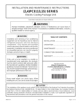
HORIZONTAL
SUPPLY AIR
OPENING
BACK VIEW
END VIEW
TOP VIEW
A
B
FRONT VIEW
HORIZONTAL
RETURN AIR
OPENING
C
L
FG
H
JK
D
E
E
D
DOWN−FLOW
SUPPLY AIR
OPENING
DOWN−FLOW
RETURN AIR
OPENING
E
D
E
D
END VIEW
CONDENSATE DRAIN
ELECTRICAL INLET
2−1/2 (64)
2−1/2 (64)
2−3/4
(70)
2−3/4
(70)
2−3/4
(70)
2−1/2 (64)
AA
CCDD
FF
BB
EE
Page 2
13CHA Unit Dimensions − inches (mm)
Model
Corner Weights
Center Of
Gravity
Model
Number
AA
BB CC DD EE FF
Number
lbs. lbs. lbs. lbs. in. in.
13CHA−24 73 91 114 92 16 29
13CHA−30 73 91 114 92 16 29
13CHA−36 80 93 117 100 16 30
13CHA−42 102 128 151 120 21 33
13CHA−48 105 129 152 124 21 33.5
13CHA−60 105 129 152 124 21 33.5
Model No
A B C D E
Model No.
in.
mm in. mm in. mm in. mm in. mm
13CHA−24
13CHA−30
13CHA−36
34−1/4 870 65−3/8 1661 36−1/2 927 11−1/4 286 17−1/4 438
13CHA−42
13CHA−48
13CHA−60
38−1/4 972 75 1905 46 1168 11−1/4 286 19−1/4 489
Model No
F G H J K L
Model No.
in.
mm in. mm in. mm in. mm in. mm in. mm
13CHA−24
13CHA−30
13CHA−36
20 508 8−1/2 216 3 76 20−1/4 514 4−1/2 114 19 483
13CHA−42
13CHA−48
13CHA−60
22 559 9−1/4 241 3−1/4 83 22−1/4 572 4 102 16−1/4 413

Page 3
Parts Arrangement
General
These installation instructions are intended as a general
guide only, for use by an experienced, qualified contractor.
The Merit
®
Series 13CHA units are single−package electric
units designed for outdoor installation on a rooftop or a
slab. The units are equipped with a transformer and blower
control for applications which do not include electric heat.
Electric heat sections are available for separate order.
The unit must be sized based on heat loss and heat gain
calculations made according to the methods of the Air
Conditioning Contractors of America (ACCA).
The units are shipped assembled. All piping, refrigerant
charge, and electrical wiring are factory−installed and
tested. The units require electric power, condensate drain
and duct connections at the point of installation.
Use of this unit as a construction heater or air conditioner
is not recommended during any phase of construction.
Very low return air temperatures, harmful vapors and
operation of the unit with clogged or misplaced filters will
damage the unit.
If this unit has been used for heating or cooling of buildings
or structures under construction, the following conditions
must be met or the warranty will be void:
A room thermostat must control the unit. The use of
fixed jumpers that will provide continuous heating or
cooling is not allowed.
A pre−filter must be installed at the entry to the return air
duct.
The return air duct must be provided and sealed to the
unit.
Return air temperature range between 55°F (13°C)
and 80°F (27°C) must be maintained.
Air filters must be replaced and pre−filter must be re-
moved upon construction completion.
The unit components, duct system, air filters and evap-
orator coil must be thoroughly cleaned following final
construction clean−up.
The unit operating conditions (including airflow, cool-
ing operation, and heating operation) must be verified
according to these installation instructions.

Page 4
Requirements
These units must be installed in accordance with all
applicable national and local safety codes.
These instructions are intended as a general guide and do
not supersede local codes in any way. Consult authorities
having jurisdiction before installation.
If components are to be added to a unit to meet local codes,
they are to be installed at the dealer’s and/or customer’s
expense.
These units are design listed by UL in both the United
States and Canada as follows:
For use as a cooling unit.
For outdoor installation only.
For installation on combustible material.
WARNING
Product contains fiberglass wool.
Disturbing the insulation in this product during
installation, maintenance, or repair will expose you
to fiberglass wool dust. Breathing this may cause
lung cancer. (Fiberglass wool is known to the State
of California to cause cancer.)
Fiberglass wool may also cause respiratory, skin,
and eye irritation.
To reduce exposure to this substance or for further
information, consult material safety data sheets
available from address shown below, or contact your
supervisor.
Lennox Industries Inc.
P.O. Box 799900
Dallas, TX 75379−9900
Location Selection
Use the following guidelines to select a suitable location for
these units.
1 − Unit is designed for outdoor installation only. Unit must
be installed so all electrical components are protected
from water.
2 − Condenser coils must have an unlimited supply of air.
3 − For ground level installation, use a level pre−fabricated
pad or use a level concrete slab with a minimum thick-
ness of 4 inches. The length and width should be at
least 6 inches greater than the unit base. Do not tie the
slab to the building foundation.
4 − Maintain level within a tolerance of 1/4 inch maximum
across the entire length or width of the unit.
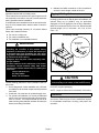
Rigging & Setting Unit
Exercise care when moving the unit. Do not remove any
packaging until the unit is near the place of installation. An
optional lifting lug kit (92M51) may be purchased
separately for use in rigging the unit for lifting. Spreaders
MUST be used across the top of the unit. Recommended
spreader length: 2, 2−1/2, 3−ton units −− 44"; 3−1/2, 4, 5−ton
units −− 54".
Figure 1
Accessory Lift Kit
Lifting Bracket
Accessory
Sheet Metal
Screw
CAUTION
Before lifting a unit, make sure that the weight is dis-
tributed equally on the cables so that it will lift evenly.
Units may also be moved or lifted with a forklift while still in
the factory supplied packaging.
NOTE − Length of forks must be a minimum of 42 inches.
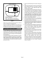
Clearances
All units require certain clearances for proper operation
and service. Refer to figure 2 for the clearances required
for combustible construction, servicing, and proper unit
operation.

Page 5
Figure 2
Service Clearances
3 (76)*
48 (1219)
30
(762)
24
(610)
*Rear clearance is 18" (457) when required for
accessory maintenance.
NOTE − Top Clearance − 36 in. (914 mm)
NOTE − Entire perimeter of unit base requires
support when elevated above mounting surface.
FRONT
REAR
NOTE − Do not permit overhanging structures or shrubs to
obstruct condenser air discharge outlet.
In the U.S. units may be installed on combustible floors
made from wood or class A, B, or C roof covering material.
In Canada, units may be installed on combustible floors.
Existing Common Vent Systems
The 13CHA packaged cooling units with auxiliary electric
heat may replace an existing furnace which is being re-
moved from a venting system commonly run with sepa-
rate gas appliances. In this case, the existing vent system
is likely to be too large to properly vent the remaining at-
tached appliances.
Conduct the following test while each appliance is operat-
ing and the other appliances (which are not operating) re-
main connected to the common venting system. If the
venting system has been installed improperly, you must
correct the system as indicated in the general venting re-
quirements section.
1 − Seal any unused openings in the common venting sys-
tem.
2 − Inspect the venting system for proper size and horizontal
pitch. Determine that there is no blockage, restriction,
leakage, corrosion, or other deficiencies which could
cause an unsafe condition.
3 − Close all building doors and windows and all doors be-
tween the space in which the appliances remaining
connected to the common venting system are located
and other spaces of the building. Turn on clothes dry-
ers and any appliances not connected to the common
venting system. Turn on any exhaust fans, such as
range hoods and bathroom exhausts, so they will oper-
ate at maximum speed. Do not operate a summer ex-
haust fan. Close fireplace dampers.
4 − Follow the lighting instructions. Turn on the appliance
that is being inspected. Adjust the thermostat so that
the appliance operates continuously.
5 − After the main burner has operated for 5 minutes, test
for leaks of flue gases at the draft hood relief opening.
Use the flame of a match or candle, or smoke from a
cigarette, cigar, or pipe.
6 − After determining that each appliance connected to the
common venting system is venting properly, (step 3)
return all doors, windows, exhaust fans, fireplace
dampers, and any other gas−burning appliances to
their previous mode of operation.
7 − If a venting problem is found during any of the preced-
ing tests, the common venting system must be modi-
fied to correct the problem.
Resize the common venting system to the minimum
vent pipe size determined by using the appropriate
tables in Appendix G. (These are in the current stan-
dards of the National Fuel Gas Code
ANSI-Z223.1/NFPA 54 in the USA, and the appropri-
ate Category 1 Natural Gas and Propane appliances
venting sizing tables in the current standards of the
CSA B149 Natural Gas and Propane Installation
Codes in Canada.)

Page 6
Condensate Drain
The 13CHA unit is equipped with a 3/4 inch FPT coupling
for condensate line connection. Plumbing must conform to
local codes. Use a sealing compound on male pipe
threads.
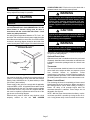
The drain line must be properly trapped and routed to a
suitable drain. See figure 3 for proper drain arrangement.
The drain line must pitch to an open drain or pump a
minimum of 1 inch per 10 feet to prevent clogging of the
line. Seal around drain connection with suitable material to
prevent air leakage into return air system.
NOTE − Drain line connection may not carry the weight of
the unsupported drain line. Support the drain line, if
necessary.
Drain piping should not be smaller than drain connection at
coil. An open vent in drain line will some times be required
due to line length, friction and static pressure. Drains
should be constructed in a manner to facilitate future clean-
ing.
NOTE − The condensate drain line MUST be trapped to
provide proper drainage.
CAUTION
Condensate line connection must be hand−tight-
ened. Do not use tools.
Figure 3
Typical Condensate Drain
Unit
Drain Connection
Positive Liquid Seal Required
3.00” Min.
1.00” Min.
12.00”
Max.
Filters
Filters are not factory−supplied with the unit; however,
optional internally installed filter kits are available. Filter kit
92M54 is used with 2, 2−1/2 and 3−ton units. Filter kit 92M55
is used with 3−1/2, 4 and 5−ton units. The filter kits
accommodate the use of 1", 2" or 4" filters. If the optional
filter kit is not used, a filter must be field−installed.
Filters must always be installed ahead of evaporator coil
and must be kept clean or replaced. Dirty filters will reduce
the airflow of the unit. Filter sizes are shown in table 1.
Table 1
Unit Filter Size
Unit Model Filter Size Filter Quantity
−24, −30, −36 20 in. X 25 in. 1
−42, −48, −60 16 in. X 25 in. 2
Supply & Return Duct Connections
The duct system should be designed and sized according
to the methods in Manual Q of the Air Conditioning
Contractors of America (ACCA).
A closed return duct system shall be used. This shall not
preclude use of economizers or outdoor fresh air intake. It
is recommended that supply and return duct connections
at the unit be made with flexible joints.
The supply and return air duct systems should be
designed for the CFM and static requirements of the job.
They should NOT be sized by simply matching the
dimensions of the duct connections on the unit.
Ducting installed outdoors MUST be insulated and
waterproofed.
CAUTION
When fastening duct system to side duct flanges on
unit, insert screws through duct flanges only. Do not
insert screws through casing. Outdoor duct must be
insulated and waterproofed.
The 13CHA unit is shipped ready for horizontal air
discharge (side duct connections). If bottom air discharge
is desired, the covers must be removed from the supply
and return air openings on the bottom of the unit and
re−installed to cover the side openings.
Figure 4
Removing Supply and Return
Air Opening Covers
Base
1.Remove screw and lift.
2.Slide cover to free back pin.
1
2

Page 7
Compressors
Units are shipped with the compressor mountings
factory−adjusted and ready for operation.
CAUTION
Do not loosen compressor mounting bolts.
Electrical
All wiring should be done in accordance with the
current National Electric Code ANSI/NFPA No. 70 in the
United States. In Canada, wiring must be done in
accordance with the current CSA C22.2 Part 1. Local
codes may take precedence.
Use wiring with a temperature limitation of 75C min.; run
the 208 or 230 volt, 60 hertz electric power supply through a
fused disconnect switch to control box of unit and connect
as shown in the wiring diagram located on the inside of the
control access panel. Refer to figure 5 for electrical access.
Figure 5
Thermostat
Entry
Line Voltage
Entry
Electrical Access
Unit must be electrically grounded in accordance with local
codes or in the absence of local codes with the National
Electric Code, ANSI/NFPA No. 70 (latest edition) or CSA
C22.2 Part 1 (latest edition).
Power supply to the unit must comply with all applicable
codes and NEC or CEC. A fused disconnect switch should
be field provided for the unit. The switch must be separate
from all other circuits. If any of the wire supplied with the
unit must be replaced, replacement wire must be of the
type shown on the wiring diagram.
Electrical wiring must be sized to carry minimum circuit
ampacity marked on the unit. USE COPPER
CONDUCTORS ONLY. Each unit must be wired with a
separate branch circuit and be properly fused.
WARNING
Unit is equipped with a single−pole contactor. Line
voltage is present at all components when unit is not
in operation. Disconnect all remote electric power
supplies before opening access panel. Unit may
have multiple power supplies. Failure to disconnect
all power supplies could result in personal injury or
death.
CAUTION
When connecting electrical power and control wir-
ing to the unit, waterproof type connectors MUST be
used so that water or moisture cannot be drawn into
the unit during normal operation.
WARNING
Unit must be grounded in accordance with national
and local codes. Failure to ground unit properly can
result in personal injury or death.
See figure 7 for typical field wiring connections and figure 8
for typical unit wiring diagram.
Optional Electric Heat
Optional electric heat is available and must be purchased
separately. Install the electric heat section as outlined in the
installation instructions packaged with the electric heat
section.
Thermostat
The room thermostat should be located on an inside wall
where it will not be subject to drafts, sun exposure or heat
from electrical fixtures or appliances. Follow
manufacturer’s instructions enclosed with thermostat for
general installation procedure. Color coded insulated wires
(# 18 AWG) should be used to connect thermostat to unit.
Blower Control Board
The circulating air blower is controlled by a blower control
board located in the unit control box. Blower operation is
NOT delayed after a call for either heating or cooling. A
blower off" delay of 90 seconds begins when the
thermostat demand is satisfied. These delays are not
adjustable. See figure 6.
NOTE − With the proper thermostat and subbase, continu-
ous blower operation is possible by closing the R to G cir-
cuit. Cooling blower delay is also functional in this mode.

Page 8
Figure 6
Blower Drive Control
Typical Single−Phase Unit Wiring Connections
Figure 7

Page 9
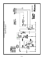
Figure 8
13CHA Series Packaged Electric Units
Typical Wiring Diagram

Page 10
Unit Start−Up and Operation
Each 13CHA packaged cooling unit is factory−charged with
R−22 refrigerant. The compressor is hermetically sealed,
internally sprung and base−mounted with rubber−insulated
hold−down bolts.
Pre−Start Check List:
1 − Make sure refrigerant lines do not rub against the cabi-
net or each other.
2 − Inspect all electrical wiring, both factory− and field−
installed, for loose connections.
3 − Check voltage at the disconnect switch. Voltage must
be within the range listed on the unit nameplate. If not,
consult power company and have voltage condition
corrected before starting unit.
4 − Recheck voltage with unit running. If power is not with-
in the range listed on the unit nameplate, stop the unit
and consult the power company. Check unit amper-
age. Refer to unit nameplate for correct running amps.
5 − Make sure filter is in place before unit start−up.
6 − Before placing the unit into full operation, energize the
unit for three false starts. Energize the compressor
just long enough for it to make a few revolutions, wait
five to seven minutes before repeating a second and
third time.
Cooling Sequence of Operation
When the thermostat calls for cooling, the R" to Y" circuit
is closed to energize the compressor contactor. The
contactor brings on both the compressor and outdoor fan.
The thermostat also closes the R" to G" circuit to energize
the circulating air blower. When the cooling demand is
satisfied, the thermostat opens the circuits, as well as the
compressor contactor. The compressor and outdoor fan
immediately stop. The circulating air blower continues
operating through a 90−second delay.
Unit compressors have internal protection. If there is an
abnormal rise in the compressor temperature, the
protector will open and the compressor will stop.
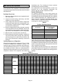
System Performance
For maximum performance of this cooling system, the
operating temperatures and pressure should be checked
and superheat determined at Standard ARI test conditions
of 82 F outdoor temperature / 80 F indoor dry bulb / 67 F
indoor wet bulb. If superheat measured deviates from
values in table 2, refrigerant charge should be adjusted
accordingly for maximum performance.
Table 2
Suction Superheat Values
Unit Model No.
Suction Superheat
82F OD / 80F IDDB
/ 67F IDWB
13CHA−24 22F
13CHA−30 20F
13CHA−36 20F
13CHA−42 20F
13CHA−48 20F
13CHA−60 20F
Verify system performance using table 3 as a general guide.
Table 3 should not be used for charging unit. Minor varia-
tions in these pressures may be expected due to differences
in installations. Significant differences could mean that the
system is not properly charged or that a problem exists with
some component in the system.
Used carefully, this table could serve as a useful service
guide. Data is based on 80°F dry bulb / 67°F wet bulb return
air. Allow unit operation to stabilize before taking pressure
readings.
Table 3
Normal Operating Pressures
80°F db / 67°F wb RETURN AIR Air Temperature Entering Outdoor Coil (°F)
UNIT PRESSURE 65 70 75 80 82 85 90 95 100 104 105 110 115
13CHA−24 78 80 82 84 85 86 88 90 91 92 92 93 94
13CHA−30 78 79 81 82 83 84 85 87 87 88 88 89 90
13CHA−36
Suction
79 80 81 83 83 84 85 86 87 88 88 89 90
13CHA−42
Suction
75 76 78 79 80 81 83 84 87 89 89 90 91
13CHA−48 76 77 79 80 81 82 83 85 85 86 86 88 91
13CHA−60 78 79 81 82 83 84 85 87 88 89 89 91 92
13CHA−24 131 146 161 176 182 191 207 221 238 250 250 268 286
13CHA−30 132 148 164 181 187 197 213 229 246 259 259 277 295
13CHA−36
Liquid
146 161 176 191 197 206 221 236 250 262 262 280 298
13CHA−42
Liquid
129 144 159 175 181 190 205 221 236 248 248 267 286
13CHA−48 131 146 161 177 183 193 208 223 240 253 253 272 291
13CHA−60 143 159 175 191 197 206 221 238 252 264 264 283 302

Page 11
Condenser Fan Clearances
The top of the condenser fan should be 1−1/2 inches from
the bottom of the top grille. This dimension should be
checked and the fan should be adjusted accordingly any
time servicing of the outdoor fan system is required.
Maintenance
At the start of each cooling season, this equipment should
be serviced by a qualified technician. Periodic inspection
and maintenance normally consists of changing or
cleaning filters and (under some conditions) cleaning the
main burners.
Filters
Not supplied. Inspect once a month. Replace disposable or
clean permanent type as necessary. DO NOT replace per-
manent type with disposable.
Motors
Indoor, outdoor fan and vent motors are permanently
lubricated and require no further lubrication. Motors
should be cleaned yearly to prevent the accumulation of
dust and dirt on the windings or motor exterior.
Coil
Dirt and debris should not be allowed to accumulate on the
coil surfaces or other parts in the air conditioning circuit.
Cleaning should be performed as often as necessary. Use
a brush, vacuum cleaner attachment, or other suitable
means. If water is used to clean the coil, be sure the power
to unit is shut off prior to cleaning.
NOTE − Care should be used when cleaning the coil so that
the coil fins are not damaged.
Do not permit the hot condenser air discharge to be ob-
structed by overhanging structures or shrubs.
Accessories
Description
LENNOX Cat.
Number
Filter Kit (2−ton to 3−ton capacity units) 92M54
Filter Kit (3−1/2−ton to 5−ton capacity units) 92M55
-
 1
1
-
 2
2
-
 3
3
-
 4
4
-
 5
5
-
 6
6
-
 7
7
-
 8
8
-
 9
9
-
 10
10
-
 11
11


Lennox 13CHA SERIES Installation Instructions Manual
- Category
- Fireplaces
- Type
- Installation Instructions Manual
Ask a question and I''ll find the answer in the document
Finding information in a document is now easier with AI
Related papers
-
Lennox 15CHAX Series User manual
-
Lennox 15GCSX User manual
-
-
-
-
Lennox Magic-Pak PWC18E10.7 User manual
-
-
-
-
Other documents
-
Allied PRGE14 Installation guide
-
 Allied Air 4SG13 series User manual
-
 Allied Air Enterprises 4)PCE(13 User manual
-
Allied 506271-01 User manual
-
COMFORT-AIRE TGRG601261M Operating instructions
-
COMFORT-AIRE TGRG601081P Operating instructions
-
-
MRCOOL MPH601M414AHK15 User manual
-
Reznor R7DA Operating instructions
-
 Heat Controller SDAH 48 Installation Instructions Manual


