COMFORT-AIRE TGRG601261M Operating instructions

Type
Operating instructions
507723-01 Page 1 of 14Issue 1650
Save these instructions for future reference
THIS MANUAL MUST BE LEFT WITH THE
HOMEOWNER FOR FUTURE REFERENCE
Do not store combustible materials, including gasoline
and other ammable vapors and liquids, near the unit,
vent pipe, or warm air ducts. Such actions could cause
property damage, personal injury, or death.
WARNING
This product contains a chemical known to the State
of California to cause cancer, birth defects, or other
reproductive harm.
WARNING
If this unit is to be installed in a mobile or manufactured
home application, the duct system must be sized to
achieve static pressures within the manufacturer’s
guidelines. All other installation guidelines must also
be followed. Failure to do so may result in equipment
damage, personal injury, and improper performance of
the unit.
WARNING
INSTALLATION AND MAINTENANCE
INSTRUCTIONS
TGRG SERIES UNITS
RESIDENTIAL PACKAGED UNITS
Gas/Electric
507723-01
12/2016
The installation of the unit, wiring, warm air ducts, venting, etc. must conform to the requirements of the National Fire
Protection Association; the National Fuel Gas Code, ANSI Z223.1 (latest edition) and the National Electrical Code, ANSI/
NFPA No. 70 (latest edition) in the United States; the Canadian Installation Codes CAN/CGA-B149.1 & .2 (latest edition)
and the Canadian Electrical Code Part 1, CSA 22.1 (latest edition) in Canada; and any state or provincial laws, local
ordinances, or local gas utility requirements. Local authorities having jurisdiction should be consulted before installation
is made. Such applicable regulations or requirements take precedence over the general instructions in this manual.
CAUTION
Table of Contents
Installation ...................................................................2
Venting.........................................................................4
Duct System ................................................................5
Filters ...........................................................................5
Condensate Drain........................................................5
Gas Piping ...................................................................6
Electrical Wiring ..........................................................7
Heating Start-Up .........................................................8
Operation ...................................................................10
Maintenance ..............................................................11
Improper installation, adjustment, alteration, service, or
maintenance can cause injury or property damage. Refer
to this manual. For assistance or additional information,
consult a licensed professional (or equivalent), HVAC
installer, service agency, or the gas supplier.
WARNING
Comfort-Aire / Century
1900 Wellworth Ave.
Jackson, MI 49203
*P507723-01*
(P) 507723-01
Page 2 of 14 507723-01Issue 1650
Installation
These instructions must be saved for future reference.
These units are single package air conditioners with gas
heat designed for outdoor installation on a rooftop or a
slab.
The units are completely assembled. All piping, refrigerant
charge, and electrical wiring are factory installed and
tested. The units require only electric power, gas piping,
condensate drain, and duct connections, plus installation
of the vent cover at the point of installation.
If components are to be added to a unit to meet local codes,
they are to be installed at the dealer’s and/or customer’s
expense.
The size of unit for the proposed installation should be
based on heat loss/heat gain calculation made according
to the methods of Air Conditioning Contractors of America
(ACCA).
In the State of Massachusetts:
This product must be installed by a licensed Plumber
or Gas Fitter. When exible connectors are used, the
maximum length shall not exceed 36”. When lever-type
gas shutoffs are used, they shall be T-handle type.
WARNING
These installation instructions are intended as a
general guide only, for use by an experienced, qualied
contractor.
These units are certied by E.T.L. Testing Laboratories,
Inc.:
For use as a forced air furnace with cooling unit.
For outdoor installation only.
For installation on combustible material.
For use with natural gas or propane gas. (Conversion
kit required for propane gas application.)
These units are not suitable for use with conventional
venting systems.
Inspection
As soon as the unit is received, it should be inspected
for possible damage during transit. If damage is evident,
the extent of the damage should be noted on the carrier’s
freight bill. A separate request for inspection by the carrier’s
agent should be made in writing.
Location
Use the following guidelines to select a suitable location
for these units.
1. Unit is designed for outdoor installation only. Unit must
be installed so all electrical components are protected
from water.
2. Condenser coils must have an unlimited supply of air.
3. For ground level installation, use a level prefabricated
pad or use a level concrete slab. Do not tie the slab to
the building foundation.
4. Maintain level within a tolerance of 1/4” maximum
across the entire length or width of the unit.
Unit levelness is critical for proper oat switch operation.
CAUTION
5. Do not locate the unit where the combustion air supply
will be exposed to any of the following substances:
Permanent wave solutions
Chlorinated waxes and cleaners
Chlorine-based swimming pool chemicals
Water softening chemicals
Deicing salts or chemicals
Carbon tetrachloride
Halogen-type refrigerants
Cleaning solvents (such as perchloroethylene)
Printing inks, paint removers, varnishes, etc.
Cements and glues
Antistatic fabric softeners for clothes dryers
Masonry acid washing materials
Chlorinated laundry products
Hydrochloric acid
507723-01 Page 3 of 14Issue 1650
Clearances
All units require certain clearances for proper operation
and service. Refer to Table 1 for the minimum clearances
to combustibles, servicing, and proper unit operation. In
the U.S., units may be installed on combustible oors
made from wood or class A, B, or C roof covering material.
In Canada, units may be installed on combustible oors.
Units must be installed outdoors.
Clearance to combustibles below the unit ue is 10 inches
since the ue points down.
Do not permit overhanging structures or shrubs to
obstruct condenser air discharge outlet, combustion
air inlet, or vent outlet.
Table 1. Minimum Clearances
Clearance to
Combustibles
Clearance for
Service Access
Front of unit 0 in. 24 in.
Back of unit 0 in. 0 in.
Left side 0 in. 24 in.
Right side (from
vent hood)
12 in. 24 in.
Base of unit 0 in. 0 in.
Top of unit 0 in. 48 in.
Minimum clearance to combustible material below the ue
is 10 inches to allow proper dissipation of ue gasses and
temperatures. For any future service, installer must provide
access to screws of top and rear panels.
Roof Curb Installation
If a roof curb is used, follow the manufacturer’s Installation
Instructions and be sure that all required clearances are
observed (see Clearances section).
Rigging Unit
Exercise care when moving the unit. Do not remove any
packaging until the unit is near the place of installation.
An optional lifting lug kit may be purchased separately for
use in rigging the unit for lifting. Spreaders whose length
exceeds the unit depth dimension by 6 inches MUST be
used across the top of the unit.
Units may also be moved or lifted with a forklift while still in
the factory supplied packaging. The lengths of the forks
of the forklift must be a minimum of 42 inches.
Figure 1.
Before lifting a unit, make sure that the weight is
distributed equally on the cables so that it will lift evenly.
CAUTION
Unpacking
Carefully remove outer packaging material and discard.
Locate the four (4) shipping brackets that attached the
unit to the wood pallet and remove. Locate the supply duct
corner and seal the shipping openings in the base from
the underside with silicone or other approved sealant to
prevent air leakage during unit operation.
Service Access
Access to all serviceable components is provided by four
removable panels: upper access panel (for blower, ID coil,
and optional lter), heat exchanger access, control access
panel, and compressor access.
As with any Mechanical equipment, personal injury can
result from contact with sharp sheet metal edges. Be
careful when you handle this equipment.
CAUTION
This unit is charged with HFC-410A refrigerant.
Operating pressures for units charged with HFC-410A
are higher than pressures in units charged with HCFC-
22. All service equipment MUST be rated for use with
HFC-410A refrigerant.
WARNING
Page 4 of 14 507723-01Issue 1650
Venting
The vent outlet must be installed in a location as to prevent
building degradation and must be consistent with the
National Fuel Gas Code, Z223.1 or CAN/CGA-B149.1 &
.2.
The products of combustion are discharged through
a screened opening on the gas heat side panel. The
horizontal vent system shall terminate at least 4 feet below,
4 feet horizontally from, or 1 foot above any door, window,
or gravity air inlet into the building. The vent system shall
terminate at least 3 feet above any forced air inlet located
within 10 feet.
The unit shall be installed in a manner such that snow
accumulation will not restrict the ow of ue products.
Minimum horizontal clearance of 4 feet from electric meters,
gas meters, regulator, and relief equipment is required.
In addition to the above requirements, consideration must
be given to prevent unwanted ice buildup from the vent
condensate. The vent should not be located on the side of
a building where the prevailing winter winds could trap the
moisture, causing it to freeze on the walls or on overhangs
(under eaves). The vent should not be located over a
sidewalk, patio, or other walkway where the condensate
could cause the surface to become slippery.
The products of combustion must not be allowed to
accumulate within a conned space where they may
be recirculated.
Vent Hood Installation
The unit is shipped with the vent hood inside the control
compartment. Locate the vent hood and attach to side of
utility panel with screws provided in the instruction bag
(see Figure 2).
Figure 2. Installing the Vent Cover
If an existing gas furnace is being removed from a
common venting system when this packaged unit is
installed, then read and follow the instructions in the
“Removal of Unit from Common Venting System” section
that follows. Otherwise, you may skip this section.
NOTE:
Removal of Unit from Common Venting System
When an existing furnace is removed from a common
venting system serving other appliances, the venting
system is likely to be too large to properly vent the
remaining attached appliances. The following test
should be conducted with each appliance while the other
appliances connected to the common venting system are
not in operation.
1. Seal any unused openings in the common venting
system.
2. Visually inspect the venting system for proper size and
horizontal pitch and determine there is no blockage
or restriction, leakage, corrosion, or other deciencies
which could cause an unsafe condition.
3. Insofar as is practical, close all building doors and
windows between the space in which the appliances
remaining connected to the common venting system
are located and other spaces in the building. Turn on
clothes dryers and any appliance not connected to the
common venting system. Turn on exhaust fans, such
as range hoods and bathroom exhausts, so they will
operate at maximum speed. Do not operate a summer
exhaust fan. Close replace dampers.
4. Following the lighting instructions, place the unit being
inspected in operation. Adjust the thermostat so the
appliance will operate continuously.
5. Test for spillage at the draft control relief opening after
5 minutes of main burner operation. Use the ame of
a match or candle.
6. Follow the preceding steps for each appliance
connected to the common venting system.
7. After it has been determined that each appliance
remaining connected to the common venting system
properly vents when tested as outlined above, return
doors, windows, exhaust fans, replace dampers,
and any other fuel burning appliance to their previous
condition of use.
8. If improper venting is observed during any of the
above tests, the common venting system must be
corrected. See National Fuel Gas Code, ANSI Z223.1
(latest edition) or CAN/CGA B149.1 & .2 Canadian
Installation Codes to correct improper operation of
common venting system.
507723-01 Page 5 of 14Issue 1650
Duct System
The duct system should be designed and sized according
to the methods in Manual Q of the Air Conditioning
Contractors of America (ACCA).
A closed return air duct system shall be used. This shall
not preclude use of economizers or outdoor fresh air
intake. It is recommended that supply and return air duct
connections at the unit be made with exible joints.
The supply and return air duct systems should be designed
for the CFM and static requirements of the job. They
should not be sized by matching the dimensions of the
duct connections on the unit.
The unit is shipped ready for horizontal ow (side duct
connections). Before attaching side ducts, bend perforated
duct tabs out to assist with duct alignment and attachment.
Duct attachment screws are intended to go into the duct
panel. Duct to unit connections must be sealed and
weather proofed.
If downow duct system is desired, a downow conversion
kit is required, and the following conversion is required.
1. Using a knife, cut following the marked cut lines on
the unit base insulation to access bottom metal covers
underneath the insulation.
2. Remove the screws securing the bottom covers, and
discard the bottom covers (supply and return).
3. Remove screws located between the supply and return
air openings that attach the blower deck to the base,
and discard these screws. These screws can interfere
with bottom duct connections or roof curb seals.
4. Secure side duct covers provided in the downow
conversion kit over the side duct openings (use
dimples on back panel to locate cover attachments).
5. Install drain pan overow switch and wire according to
downow conversion kit instructions.
Filters
Air lters are not supplied with the unit. A eld-provided air
lter must always be installed ahead of the evaporator coil
and must be cleaned or replaced if necessary. Dirty lters
will reduce the airow of the unit.
An optional lter rack kit may be purchased separately
for installation inside the unit’s coil compartment. Air lter
sizes are shown in Table 2 for use with lter rack kit.
The lter rack must be installed prior to installation of
the unit in applications where access to the rear panel
is limited.
NOTE:
Table 2. Unit Air Filter Sizes - inches
Unit Model Filter 1 Filter 2
24, 30, 36 14 X 20 20 X 20
42, 48, 60 20 X 20 20 X 20
Condensate Drain
This package unit is equipped with a 3/4” FPT coupling
for condensate line connection. Plumbing must conform
to local codes. Use a sealing compound on male pipe
threads.
Do not operate unit without a drain trap. The condensate
drain is on the negative pressure side of the blower;
therefore, air being pulled through the condensate line will
prevent positive drainage without a proper trap.
The condensate drain line must be properly trapped,
routed to a suitable drain and primed prior to unit
commissioning.
NOTE: Install drain lines and trap so they do not block
service access to the unit.
See Figure 3 for proper drain arrangement. The drain line
must pitch to an open drain or pump to prevent clogging
of the line. Seal around the drain connection with suitable
material to prevent air leakage into the return air system.
To prime trap, pour several quarts of water into drain,
enough to ll drain trap and line.
Drain lines should be hand-tightened only. Do not use
tools to tighten tting into drain.
CAUTION
Page 6 of 14 507723-01Issue 1650
Gas Piping
Proper sizing of a gas piping depends on the cubic feet per
hour of gas ow required, specic gravity of the gas, and
length of run. National Fuel Gas Code Z223.1 latest edition
should be followed in all cases unless superseded by local
codes or gas company requirements. In Canada, refer to
CAN/CGA B.149.1 & .2 (latest edition).
The heating value of the gas may differ with locality. The
value should be checked with the local gas utility. For
temperature rise of unit, see unit rating plate.
Gas Piping Recommendations
A drip leg and a ground joint union must be installed in
the gas piping. A ground joint union is recommended
by the manifold/valve.
When required by local codes, a manual shutoff valve
may have to be installed outside of the unit.
Use pipe thread sealing compound resistant to
propane gas sparingly on male threads.
The gas supply should be a separate line and installed
in accordance with all safety codes listed on Page
1. After the gas connections have been completed,
open the main shutoff valve admitting normal gas
pressure to the mains. Check all joints for leaks
with soapy solution or other material suitable for the
purpose.
Never use a ame to check for gas leaks. Explosion
causing injury or death may occur.
WARNING
The furnace and its eld supplied manual shutoff valve
must be disconnected from the gas supply piping
system during any pressure testing of that system at
test pressures in excess of 1/2 PSIG (3.48kPa).
A 1/8” N.P.T. plugged tapping, accessible for test
gauge connections, must be installed immediately
upstream of the gas supply connection to the furnace.
Gas Connection
The gas supply line is routed through the gas entry
location on the side of the unit (see Figure 4). A grommet is
provided in the instruction bag and should be used to seal
gas supply line to gas entry of control compartment.
Figure 4.
The furnace must be isolated from the gas supply piping
system by closing the eld supplied manual shutoff valve
during any pressure testing of gas supply piping system
at test pressures equal to or less than 1/2 psig or 14”
w.c. If the piping system is to be tested at pressures in
excess of 1/2 psig, the furnace and its individual shutoff
valve must be disconnected from the gas supply piping
system.
WARNING
NOTE: LPG/Propane Units, Tanks, and Piping
Units are shipped equipped for use with natural gas,
but can be converted to LPG/propane in the eld by an
approved licensed technician. If conversion is required,
use the approved conversion kit.
Figure 3. Typical Condensate Drain Connection
MINIMUM PITCH
1 IN (25) PER 10” (3048
MM) OF LINE
OPEN
VENT
UNIT
MOUNTING
FRAME
Trap must be deep enough to offset maximum static difference
(generally, 3 inches (76 mm) minimum). In addition, the drain line
must be supported if longer than 10 feet.
Trap must be primed at start-up.
507723-01 Page 7 of 14Issue 1650
When converting a low NOx unit (designated by an L in
some model numbers) to propane, the NOx inserts must
be removed.
All LPG/propane gas equipment must conform to the safety
standards of the National Fire Protection Association.
For satisfactory operation, LPG/propane gas pressure
must be a minimum of 11” w.c. at the unit under full load.
Complete information regarding tank sizing for
vaporization, recommended regulator settings, and pipe
sizing is available from most regulator manufacturers and
LPG/propane gas suppliers.
Check all connections for leaks when piping is completed,
using a soapy, non-chlorine based solution. Some soaps
used for leak detection are corrosive to certain metals.
Carefully rinse piping thoroughly after completing
leak detection.
Danger of explosion. Can cause injury or product or
property damage. Do not use matches, candles, ame
or other sources of ignition to check for leaks.
WARNING
If a exible gas connector is required or allowed by
the authority that has jurisdiction, black iron pipe shall
be installed at the gas valve and must extend outside
the cabinet. The exible connector can then be added
between the black iron pipe and the gas supply line.
CAUTION
Electrical Wiring
See Figure 4 and Figure 5
All wiring should be done in accordance with the National
Electrical Code, ANSI/NFPA No. 70 (latest edition);
Canadian Electrical Code Part 1, CSA C22.1 (latest
edition); or local codes where they prevail. Use wiring with
a temperature limitation of 75°C minimum. Run the 208 or
230 volt, 60 hertz electric power supply through a fused
disconnect switch to the control box of the unit and connect
as shown in the wiring diagram located on the inside of the
control access panel.
Power supply to the unit must be N.E.C. Class 1, and must
comply with all applicable codes. A fused disconnect switch
should be eld provided for the unit. The switch must be
separate from all other circuits. If any of the wire supplied
with the unit must be replaced, replacement wire must be
of the type shown on the wiring diagram. Electrical wiring
must be sized to carry minimum circuit ampacity marked
on the unit. Use copper conductors only. Each unit must
be wired with a separate branch circuit and be properly
fused.
Figure 5. 208/230 Line Voltage Wiring
SINGLE PHASE
POWER SUPPLY
GROUND
LUG
CONTACTOR
FIELD-SUPPLIED FUSED
OR CIRCUIT BREAKER
DISCONNECT
If 208 Volt is supplied, transformer connection must be
changed
When connecting electrical power and control wiring
to the unit, waterproof type connectors must be used
so that water or moisture cannot be drawn into the unit
during normal operation.
CAUTION
Thermostat
The room thermostat should be located on an inside
wall where it will not be subject to drafts, sun exposure,
or heat from electrical xtures or appliances. Follow the
manufacturer’s instructions enclosed with thermostat for
general installation procedure. Color-coded insulated wires
(#18 AWG) should be used to connect the thermostat to
the unit.
Four wires are required for cooling. The heat anticipator
setting is 0.75 amp.
Compressor
Units are shipped with compressor mountings factory-
adjusted and ready for operation.
Do not loosen compressor mounting bolts.
CAUTION
Page 8 of 14 507723-01Issue 1650
Figure 6. Typical Wiring Connections
Red
Blue
Yellow
White
Green
75
Heating Start-Up
For Your Safety, Read Before Lighting
Furnace is equipped with a direct ignition control. Do
not attempt to manually light the burners.
CAUTION
Pre-Start Checklist
Complete the following checks before starting the unit:
1. Check the type of gas being supplied. Be sure it is the
same as listed on the unit nameplate.
2. Make sure that the vent cover has been properly
installed.
To Light Main Burners
1. Turn off electrical power to unit.
2. Turn the thermostat to lowest setting.
3. Slide the gas valve switch to the “ON” position (see
Figure 7).
4. Turn on electrical power to the unit.
5. Set the room thermostat to the desired temperature.
(If the thermostat “set” temperature is above room
temperature after the pre-purge time expires, main
burners will light.)
To Shut Down Main Burners
1. Turn off electrical power to unit.
2. Slide the gas valve switch to the “OFF” position (see
Figure 7).
Regulator
Adjustment
Figure 7. Gas Valve
Post-Start Checklist
After the entire control circuit has been energized and the
heating section is operating, make the following checks:
1. Check for gas leaks, using soapy solution, in the unit
piping as well as the supply piping.
2. Check for correct manifold gas pressures (see Manifold
Gas Pressure Adjustment Regulator sections).
3. Check the supply gas pressure. It must be within the
limits shown on the rating plate. Supply pressure
should be checked with all gas appliances in the
building at full re. At no time should the standby gas
pressure exceed 13” w.c., nor the operation pressure
drop below 5” w.c. for natural gas units or 11” w.c. for
propane gas. If gas pressure is outside these limits,
contact the gas supplier for corrective action.
4. Adjust temperature rise to the range specied on the
rating plate.
Manifold Gas Pressure Adjustment Regulator – Natural
Gas
For purpose of input adjustment, the minimum permissible
gas supply pressure is 5” w.c. for natural gas.
Gas input must never exceed the input capacity shown on
the rating plate. The furnace is equipped for natural gas
rated inputs with manifold pressure of 3.5” w.c.
The manifold pressure can be measured by shutting off
the gas, removing the pipe plug in the downstream side
of the gas valve, and connecting a water manometer
or gauge. Under no circumstances should the nal
507723-01 Page 9 of 14Issue 1650
manifold pressure vary more than 0.3” w.c. from the
above specied pressures. To adjust the regulator, turn
the adjusting screw on the regulator clockwise to increase
pressure and input or counterclockwise to decrease
pressure and input. See Figure 7 to assist in locating the
regulator on the gas valve.
Check the furnace rate by observing the gas meter, making
sure all other gas appliances are turned off. The test hand
on the meter should be timed for at least one revolution,
noting the number of seconds per revolution. The heating
value of the gas can be obtained from the local utility.
BTU/HR
Input
=
Cubic Feet per
Revolution
x 3600 x
Heating
Value
# Seconds per
Revolution
For example, by actual measurement, it takes 38 seconds
for the hand on the 1-cubic foot dial to make a revolution
with a 100,000 BTU/HR furnace running. The result is
99,750 BTU/HR, which is close to the 100,000 BTU/HR
rating of the furnace.
Manifold Gas Pressure Adjustment Regulator – LPG/
Propane Gas
LPG/propane units require a LPG regulator on both the
gas valve and on the LPG/propane tank.
IMPORTANT: For purpose of input adjustment, the
minimum permissible gas supply pressure (inlet side of
gas valve) is 11” w.c. for LPG/propane.
If at any time ignition is slow and burner does not seem to
be operating correctly, check manifold pressure (outlet side
of the gas valve). It should be 10” to 10.5” w.c. pressure
for LPG/propane.
The furnace is designed to obtain rated input at 10”
w.c. manifold pressure for propane.
High Altitude
The input rate shown on the rating plate is for elevations
up to 2000 feet. For elevations from 2001 to 4500 feet,
the input rate is reduced by 5%. For elevations above
4500 feet, refer to the National Fuel Gas Code Z223.1
(latest edition) or the Canadian Installation Codes CAN/
CGA-B149.1 & B149.2 for further details.
To check this pressure:
1. Slide the gas valve switch to the “OFF” position (see
Figure 7).
2. Remove plug on valve marked “OUTLET PRESSURE.”
3. Install a water manometer.
4. Slide the gas valve switch to the “ON” position and
initiate a call for heat. If manifold pressure must be
adjusted, remove cap from pressure regulator and
turn adjustment screw clockwise to increase pressure
or counterclockwise to reduce pressure.
5. After checking pressure, turn gas off, remove
manometer tting, and replace pipe plug and regulator
cap.
6. Put furnace in operation and check plug for leaks
using soapy solution.
Burner and Burner Orice Instructions
To check or change burners or burner orices:
1. Close the main manual gas shutoff valve and turn
off all power to unit.
2. Remove the burner access panel.
3. Disconnect the union in the gas supply line upstream
of the gas valve and downstream of the manual shutoff
valve.
4. Label wires going to the gas valve, then disconnect
the wires.
5. To change orice:
a. Remove screws that fasten the manifold to the
burner box assembly and remove the manifold.
b. Remove the orices, then install replacement
orices.
c. To reassemble: Reverse above steps, making
sure orices are inserted into the orice holders
on the back end of the burners, and that burners
are level and centered on each burner opening in
the vest panel.
6. To remove or service burners:
a. Label and disconnect the wires to the rollout switch
and disconnect the igniter and ame sensor leads
at the ignition control.
b. Remove the screws that secure the burner box
assembly to the vest panel and remove the
assembly from the unit.
c. Remove the screws that fasten the burner rack
and bottom shield assembly to the burner box.
Burners are now accessible for removal.
d. To Reassemble: Reverse above steps.
7. After reassembly of all parts is complete and all wires
are reconnected, open the main manual gas shutoff
valve; check for and correct any gas leaks. Turn
electrical power on, initiate a call for heat, and check
for proper burner operation.
8. Install burner access panel.
Heat Anticipator
The heat anticipator setting is 0.75 amp. It is important
that the anticipator setpoint be correct. Too high of a setting
will result in longer heat cycles and a greater temperature
swing in the conditioned space. Reducing the value below
the correct setpoint will give shorter “ON” cycles and
may result in the lowering of the temperature within the
conditioned space.
Page 10 of 14 507723-01Issue 1650
Operation
Cooling System
The cooling system is factory-charged with HFC-R-410A.
The compressor is hermetically sealed and base-mounted
with rubber-insulated bolts.
Cooling Sequence of Operation
When the thermostat calls for cooling, R is closed to Y (see
the wiring diagrams). This action completes the low voltage
control circuit, energizing the compressor, condenser fan
motor, and blower motor.
Unit compressors have internal protection. In the event there
is an abnormal rise in the temperature of the compressor,
the protector will open and cause the compressor to stop.
Blower Delay – Cooling
The circulating air blower is controlled by a timing circuit
in the integrated blower/ignition control. Timings are not
adjustable. Blower “ON” delay is 5 seconds after the
compressor starts and blower “OFF” timing is 60 seconds
after the compressor shuts down.
NOTE: There is no blower OFF delay when there is a call
for G (fan only).
Cooling System Performance
This equipment is a self-contained, factory-optimized
refrigerant system. The unit should not require adjustments
to system charge when properly installed. If unit
performance is questioned, perform the following checks.
Ensure unit is installed per manufacturer’s instructions and
that line voltage and air ow are correct. Refer to Table 3
for proper performance value. The indoor metering device
varies by model. When checking performance of a unit
using an orice for metering, refer to the suction superheat
value to judge performance. When checking performance
of a unit that uses an expansion valve for metering, refer
to the subcooling value to judge system performance. If
the measured performance value varies from table value
allowance, check internal seals, service panels and duct
work for air leaks, as well as restrictions and blower
speed settings. If unit performance remains questionable,
remove system charge, evacuate to 500 microns, and
weigh in refrigerant to nameplate charge. It is critical that
the exact charge is re-installed. Failure to comply will
compromise system performance. If unit performance is
still questionable, check for refrigerant-related problems,
such as blocked coil or circuits, malfunctioning metering
device or other system components.
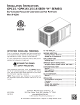
Cooling System Performance Values
Model
Suction
Superheat +/- 3°
Liquid
Subcooling +/- 2°
2 Ton 10
2.5 Ton 14
3 Ton 13
3.5 Ton 12
4 Ton 14
5 Ton 17
Based on outdoor ambient temperature of 82°F, and indoor
entering air of 80°F db, 67°F wb.
Table 3.
Heating System
With the proper thermostat and sub-base, continuous
blower operation is possible by closing the R to G circuit.
Cooling blower delay is also functional in this mode.
Heating Sequence of Operation
When the thermostat calls for heating, R is closed to W. The
following describes the gas heating sequence of operation.
1. A call for heat from the room thermostat starts the
combustion air blower and the circulating air blower.
2. When the speed of the combustion air blower reaches
proper RPM, the pressure switch closes, initiating a
pre-purge period (30 seconds nominal).
3. When the pre-purge period has expired, the ignition
control energizes the main gas valve and spark
electrode for a period of 10 seconds.
4. If the ame sensor does not sense that a ame has
been established in the 10-second interval, then the
ignition control will de-energize the gas valve, and
begins a 30 second inter-purge period, then initiates
another trial for ignition.
5. The ignition control is designed to repeat this “trial
for ignition” a total of three times. If, at the end of the
third trial, ame still has not been established, then the
ignition control will try to light again 1 hour later. The
1-hour retry is indenite. The ignition control can be
reset by interrupting the unit power or the thermostat
circuit.
6. Once ame sense has been established, the circulating
air blower is energized after a 30 second blower on
delay.
7. When the thermostat is satised, the combustion air
blower and gas valve are de-energized. The circulation
air blower will continue to run for a short period after
the furnace is shut down.
Blower OFF Delay – Heating
The circulating air blower “OFF” delay is 120 seconds after
shutting down the burners. This delay is not adjustable.
507723-01 Page 11 of 14Issue 1650
Safety Controls
The control circuit includes the following safety controls:
Limit Control
This control is located inside the heating compartment
and is designed to open at abnormally high circulating
air temperatures. It resets automatically. The limit control
operates when a high temperature condition, caused by
inadequate airow, occurs. This closes the main gas valve.
Pressure Switch
If the combustion air blower should fail, the pressure
switch prevents the spark electrode and gas valve from
being energized.
Flame Sensor
If the ignition control does not receive a signal from the
ame sensor indicating that the burners have established
ame, the gas valve closes after the 10-second trial for
ignition period.
Rollout Switch
The switch is located on the top of the burner box. In the
event of a sustained main burner rollout, the rollout switch
shuts off the ignition control and closes the main gas valve.
To reset, push the button on top of the switch.
Secure Owners Approval
When the system is functioning properly, secure the owner’s
approval. Show the owner the location of all disconnect
switches and the thermostat. Instruct the owner on how
to start and stop the unit and how to adjust temperature
settings within the limitations of the system.
Maintenance
Periodic inspection and maintenance normally consists of
changing or cleaning the lters and cleaning the outdoor
coil. On occasion, other components of the furnace may
also require cleaning.
Shut off all electrical power to the unit before conducting
any maintenance procedures. Failure to do so could
cause personal injury.
WARNING
Filters
Filters are not supplied with the unit. Inspect once a month.
Replace disposable or clean permanent type as necessary.
Do not replace permanent type with disposable.
Motors
Indoor and outdoor fan and vent motors are permanently
lubricated and require no maintenance.
Outdoor Coil
Dirt and debris should not be allowed to accumulate on
the outdoor coil surface or other parts in the air circuit.
Cleaning should be as often as necessary to keep coil
clean. Use a brush, vacuum cleaner attachment, or other
suitable means. If water is used to clean the coil, be sure
the power to unit is shut off prior to cleaning. Care should
be used when cleaning the coil so that the coil ns are
not damaged.
Do not permit the hot condenser air discharge to be
obstructed by overhanging structures or shrubs.
Burners
To clean the burners, rst remove them from the furnace
as explained in the Burner and Burner Orice Instructions
section. Vacuum and/or brush as required.
Vent Outlet
Visually inspect vent outlet periodically to make sure that
there is no buildup of soot or dirt. If necessary, clean to
maintain adequate opening to discharge ue products.
Page 12 of 14 507723-01Issue 1650
Heat Exchanger
With proper combustion adjustment, the heat exchanger
of a gas-red furnace will seldom need cleaning. Sooting
of a gas appliance is highly irregular and once cleaned,
the cause of the sooting must be determined. If the heat
exchanger should become sooted, it can be cleaned as
follows:
1. Remove the burner assembly as outlined in the Burner
and Burner Orice Instructions section.
2. Remove the combustion blower.
3. At the bottom of the heating section, remove the screws
holding the ue collector box. Carefully remove the ue
collector box without ripping the adjacent insulation.
4. Using a wire brush on a exible wand, brush out the
inside of each heat exchanger from the burner inlet
and ue outlet ends.
5. Brush out the inside of the ue collector box.
6. Run the wire brush down the heat exchanger tubes
from the ue collector end.
7. If soot buildup is excessive, remove the vent motor and
clean the wheel and housing. Run the wire brush down
the ue extension at the outlet of the vent housing.
8. After brushing is complete, blow all brushed areas with
air. Vacuum as needed.
9. Replace parts in the reverse order they were removed
in Steps 1 through 3.
10. When replacing the ue collector box, be careful so as
not to tear the adjoining insulation.
11. Assure that all joints on the vent side of the combustion
system are air tight. Apply a high temperature (+500°F)
sealing compound where needed.
Control System Diagnostics
Table 4. Fault Codes
LED Status Flashing Rate Fault Description
Slow Flash
One ash
per second
Normal operation:
No call for heat
Fast Flash
Two ashes
per second
Normal operation:
Call for heat
2 Flash
Two ashes
in second with
1-second pause
System lockout:
Failed to detect or
sustain ame
3 Flash
Three ashes in
1.5 seconds with
1-second pause
Pressure switch senses
incorrect pressure or gas
valve coil is open.
4 Flash
Four ashes in
2 seconds with
1-second pause
High limit or rollout
switch open
5 Flash
Five ashes in
2.5 seconds with
1-second pause
Flame sensed and gas
valve not energized
Steady --
Internal failure:
Micro-controller failure;
self-check
507723-01 Page 13 of 14Issue 1650
Figure 8. Wiring Diagram – Single Phase PSC
Y
G
W
R
C
WHT
W/ RED
BRN
BLU
BRN
RED
WHT
PUR
BLK
GRN
BLK W/ WHT
PUR
RED
YEL
YEL
YEL
T2
L2
C
H
F
BLK W/ WHITE
BLK
PUR
ORG
GREY
RED
BLK
INDOOR
BLOWER
MOTOR
BLK
BLU
YEL
HEAT ANTICIPATION SETTING: 0.75 AMP
BLU
E1
C4
CAPACITOR
H
M
L
C
* JUMPER REQUIRED
IF THE JUMPER IS NOT USED, CONNECT
RED W/STRIPE WIRE TO THE HEAT TERMINAL.
BLU
5
MOTOR
SPEED TAPS
(IF USED)
THERMAL PROTECTION
SWITCH (IF USED)
208/230-1-60
POWER SUPPLY WITH MIN.
75
C COPPER WIRE
Y G
W1
R C
GRN
YEL
WHT
RED
24VAC
1
6 2 5
4
3
FLAME
FLAME SENSE
MAIN
LIMIT
SWITCH
ROLLOUT
SWITCH
PRESSURE
SWITCH
GAS VALVE
FUSE
IGNITION CONTROL
CONTACTOR
CONTROL CIRCUIT WIRING TO
BE 24 VOLT, N.E.C. CLASS 2
HIGH PRESSURE
SWITCH
L1
T1
CONDENSER
FAN MOTOR
COMPRESSOR
CONTACTOR
COMPRESSOR
CONTACTOR
DUAL
CAPACITOR
COMPRESSOR
TRANSFORMER
C
S
R
L1
CMB BLWR
SPARK
COMB.
AIR
BLOWER
IGNITION CONTROL
537658-01
24V
NOTE:
IF ANY OF THE ORIGINAL
WIRE IS REPLACED THE
SAME SIZE AND TYPE WIRE
MUST BE USED.
USE COPPER CONDUCTOR
ONLY, MIN 75
C WIRE
LINE VOLTAGE FIELD INSTALLED
WARNING-
ELECTRIC SHOCK HAZARD. UNIT
MUST BE GROUNDED IN ACCORDANCE
WITH NATIONAL AND LOCAL CODES.
S4
S1
K1
A3
GV1
S18
S47
S10
T1
B3
B6
B4
K1-2
C12
B1
K1-1
A3
GROUND
DIAGNOSTICS � IGNITION CONTROL
The following ignition control board LED codes will
indicate normal or abnormal operations:
SLOW FLASH Normal operation, no call for heat.
FAST FLASH Normal operation, call for heat.
2 FLASH System lockout � failed to detect or sustain flame.
3 FLASH Pressure switch senses incorrect pressure.
4 FLASH Main limit open or rollout switch open.
5 FLASH Flame sensed and gas valve not energized.
STEADY Internal failure (micro-controller failure; self check)
LED
BLU W/
STRIPE
RED W/
STRIPE
SEE CHART
FOR WIRING
BLK
WHT
BLK W/ WHT
DRK BLU
FLOAT
SWITCH
(IF USED)
LOW PRESSURE
SWITCH (IF USED)
240 V
208 V
S79
S173
2
3
4
1
J1-2
J1-1
J1-3
J1-12
J1-11
J1: PLUG THROUGH CONTROL PANEL (12 PIN)
CONNECTION DIAGRAM
GAS/ELECTRIC (PSC BLOWER)
SINGLE PHASE
THERMOSTAT
4
3
1
2
ACB
COOL
ACB
HEAT
CRANK
CASE
HEATER
(IF USED)
BLK
BLK
HR1
BLOWER SPEED CHART
UNIT INPUT
COOLING/
HEATING
COOL
(BLUE
W/ STRIPE)
HEAT
(RED W/
STRIPE)
24/54 5* 5
24/72 5 4
30/54 3 5
30/72 3 4
36/54 3 4
36/72 3* 3
36/90 3* 3
42/72 3 4
42/90 3* 3
48/108 3 4
48/126 3* 3
Page 14 of 14 507723-01Issue 1650
Figure 9. Wiring Diagram – Single Phase CT
208/230-1-60
POWER SUPPLY WITH MIN.
75
C COPPER WIRE
Y G
W1
R
C
Y
G
W
R
C
GRN
YEL
WHT
RED
24VAC
1
6 2 5
3
4
FLAME
FLAME SENSE
WHT
W/ RED
BRN
RED
BLU
BLK
WHT
PUR
BLK
GRN
BRN
PUR
MAIN
LIMIT
SWITCH
ROLLOUT
SWITCH
PRESSURE
SWITCH
GAS VALVE
FUSE
IGNITION CONTROL
RED
CONTROL CIRCUIT
WIRING TO BE 24 VOLT,
N.E.C. CLASS 2
HIGH PRESSURE
SWITCH
L1
T1
T2
L2
C
H
F
CONDENSER
FAN MOTOR
COMPRESSOR
CONTACTOR
COMPRESSOR
CONTACTOR
DUAL
CAPACITOR
COMPRESSOR
TRANSFORMER
C
S
R
L1
CMB BLWR
SPARK
COMB.
AIR
BLOWER
IGNITION CONTROL
BLK W/ WHT
537659-01
CONNECTION DIAGRAM
GAS/ELECTRIC (CONSTANT TORQUE BLOWER)
SINGLE PHASE
BLK
PUR
GRY
RED
BLK
208V
240V
24V
INDOOR
BLOWER
MOTOR
NOTE:
IF ANY OF THE ORIGINAL
WIRE IS REPLACED THE
SAME SIZE AND TYPE WIRE
MUST BE USED.
USE COPPER CONDUCTOR
ONLY, MIN 75
C WIRE
LINE VOLTAGE FIELD INSTALLED
WARNING-
ELECTRIC SHOCK HAZARD. UNIT
MUST BE GROUNDED IN ACCORDANCE
WITH NATIONAL AND LOCAL CODES.
S4
S1
A3
GV1
S18
S47
S10
B6
B4
K1-2
C12
B1
K1-1
A3
GROUND
BLU
YEL
HEAT ANTICIPATION SETTING: 0.75 AMP
DIAGNOSTICS � IGNITION CONTROL
The following ignition control board LED codes will
indicate normal or abnormal operations:
SLOW FLASH Normal operation, no call for heat.
FAST FLASH Normal operation, call for heat.
2 FLASH System lockout � failed to detect or sustain flame.
3 FLASH Pressure switch senses incorrect pressure,
aux. limit is open or gas valve coil is open
4 FLASH Main limit open or rollout switch open.
5 FLASH Flame sensed and gas valve not energized.
STEADY Internal failure (micro-controller failure; self check)
LED
E1
N
ACB
COOL
ACB
HEAT
1
2
3
4
5
BLOWER MOTOR TERMINAL BLOCK
BLU
BLU
GRN
BLK
BLK
KI
CONTACTOR
NOTE: TAP 1 FOR FAN ONLY
TAP2: COOLING
TAP3: HIGH STATIC COOLING
TAP4: HEATING
TAP5: HIGH STATIC HEATING
ORG
B3
YEL
L
N
G L C
WHT
BLK W/ WHT
BLK
THERMAL PROTECTION
SWITCH (IF USED)
BLK
BLK W/ WHT
GRN
RED
GRN
WHT
BLU
YEL
LOW PRESSURE SWITCH
(IF USED)
WHT
DRK BLU
J1: PLUG THROUGH CONTROL PANEL (12 PIN)
J1-2
J1-3
FLOAT SWITCH (IF USED)
T1
J1-1
S79
S173
P1-11
P1-12
THERMOSTAT
CRANK
CASE
HEATER
(IF USED)
BLK
BLK
HR1
  • Page 1 1
  • Page 2 2
  • Page 3 3
  • Page 4 4
  • Page 5 5
  • Page 6 6
  • Page 7 7
  • Page 8 8
  • Page 9 9
  • Page 10 10
  • Page 11 11
  • Page 12 12
  • Page 13 13
  • Page 14 14

COMFORT-AIRE TGRG601261M Operating instructions

Type
Operating instructions

Ask a question and I''ll find the answer in the document

Finding information in a document is now easier with AI