Unbranded LP Conversion Kit, 920610 Installation guide
- Type
- Installation guide

These instructions are primarily intended to assist qualifi ed
individuals experienced in the proper installation of this
appliance. Some local codes require licensed installation/
service personnel for this type of equipment.
IMPORTANT: Read all instructions before beginning
the conversion of the appliance.
This conversion kit is only for United States installations to
convert a natural gas furnace to either a propane (LP) gas
application or a high altitude LP application. For Canadian
installations, the Canadian conversion kit must be used.
This conversion kit is backwards compatible with R4GM
& R4GN units. Contact NORDYNE Technical Services for
more information on these appliances.
To Turn Off the Fuel Supply to the Appliance:
1. Set the room thermostat to “OFF” or its lowest tempera-
ture setting.
2. Turn OFF the main gas supply to the appliance at the
manual valve, outside of the appliance casing.
3. Turn OFF all electrical power to the appliance.
4. Remove the burner access panel louvered door.
5. Move the appliance gas valve lever/knob to the “OFF”
position. See Figures 1 and 3.
To Remove the Burner Manifold Assembly:
1. Follow the instructions “To Turn Off the Fuel Supply
to the Appliance”.
2. Disconnect the fl ame sensor wire at the burner box.
3. Disconnect the spark ignitor wire at the burner box.
4. Remove the white wires from the Stage-1 terminal of
the gas valve. Remove the brown wire from the Stage-2
terminal of the gas valve. Remove black common wire
from gas valve.
5. Remove (if installed) supply gas piping from the gas
valve.
6. Remove the four (4) fasteners that secure the gas mani-
fold to the burner box, as shown in Figure 1. Carefully
remove the gas manifold assembly from the burner box.
Note that the gas manifold assembly consists of the gas
valve, the gas manifold, and the orifi ces.
7. Identify the gas valve manufacturer listed on the gas
valve label. Convert the valve for operation with LP gas
as described in the appropriate manufacturers instruc-
tions. (Included)
LP and High Altitude LP Gas Conversion Kit
For United States Installations (0 - 10,000 ft.)
Installation Instructions
R6GP Light Commercial Packaged Gas Electric Units
WARNING:
This conversion kit is to be installed by a qualifi ed
service technician in accordance with these
instructions and all codes having jurisdiction.
Failure to follow these instructions could result
in serious injury, property damage, or death. The
qualifi ed service technician performing this work
assumes responsibility for this conversion.
All gas piping must conform with local building
codes or, in the absence of local codes, with most
recent edition of the National Fuel Gas Code
ANSI Z223.1. All electrical wiring must comply
with the latest edition of the National Electrical
Code ANSI/NFPA 70.
CAUTION:
The gas supply shall be shut off prior to
disconnecting the electrical power, before
proceeding with the conversion.
CAUTION:
Caution: Do not re-drill the burner orifi ces.
If the orifi ce size must be changed, use only
new orifi ces.
CAUTION:
Note: The size of the new orifi ces that will be installed
into the unit will depend upon the type of conversion
(sea level or high altitude). Please refer to Table 1 for
more details on your particular conversion.
WARNING:
DO NOT REMOVE OR DEFACE THE ORIGINAL
RATING PLATE.

2

3
4. For units converted for operation above 2000 ft., follow
the High altitude deration instructions.
High Altitude Deration
High altitude application with this unit depends on the
installation altitude and the heating value of the gas. At
high altitudes, the heating value of natural gas is always
lower than the heating value at sea level.
All installations of this equipment must be made in
accordance with the National Fuel Gas Code or with local
jurisdiction codes. For installations at exactly 2,000 feet
in altitude or under, the installer does not need to derate
the heat exchanger performance. For any installation that
exceeds 2,000 feet, please see the following instructions
and example:
WARNING:
The reduction of input rating necessary for high
altitude installation may only be accomplished
with factory supplied orifi ces. Do not attempt to
drill out orifi ces in the fi eld. Improperly drilled
orifi ces may cause fi re, explosion, carbon mon-
oxide poisoning, personal injury or death.
• If installing this unit above 2,000 feet, the input rate must
be reduced 4% per 1,000 feet of altitude (Example: 12%
at 3,000 feet, 16% at 4,000 feet, etc). Always round up
to the next highest value of 1,000. So an installation at
3,120 feet is derated by 16% due to rounding up to 4,000.
NOTE: This deration is necessary to compensate for low
atmospheric pressure at high altitudes. Generally this will
require obtaining the gas heating value from the local gas
utility and replacing the burner orifi ces.
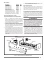
Figure 1. Typical Installation For R4GM Burner Box
Kit Includes:
Description Part No. Qty.
Burner Orifi ce # 51 636051 7
Burner Orifi ce # 52 636052 7
Burner Orifi ce # 53 636053 7
Burner Orifi ce # 54 661054 5
Burner Orifi ce # 55 661055 5
Conversion Warning Label 703935 1
Conversion Information Label 710005 1
These Installation Instructions 709010 1
Honeywell Gas Valve Conv. Kit 624667 1
White Rodgers Gas Valve Conv. Kit 618094 1
To Convert the Unit to LP Gas
for Altitudes Between 0 and 10,000 Feet
1. Table 1 is a detailed listing of orifi ces required for
converting R6GP Series units to LP Gas for altitudes
between 0 and 10,000 feet. Please check the contents
of the conversion kit with that of the parts listing, and
familiarize yourself with each component.
2. Examine the rating plate of the unit to determine Model
number and rated input (Btu/hr). Count the number of
burners in the burner box. Cross check all information
with Table 1 to determine the appropriate LP gas orifi ce
size for your application.
3. Install the appropriate LP gas burner orifi ces into the
gas manifold. Before installing an orifi ce, check the face
or side of the orifi ce for the drill number to ensure that it
is the appropriate size. When installing the new orifi ces,
DO NOT use pipe joint compound on the orifi ce threads.
Screw the orifi ces into the manifold by hand until snug
to eliminate cross threading, then tighten with a wrench,
1/2 to 1 turn.
Gas Valve
Gas Manifold
On/Off
Lever/Switch/Knob
Fasteners
Burner
Orifices
Flame Sensor
Spark
Ignitor
Burners
Burner
Box

4
• Table 1 lists the correct orifi ce size to use at different
altitudes. See Installation Example 1 to determine the
unit rating and orifi ce size.
• After changing the orifi ces, it is required that you
measure the gas input rate by clocking the gas
meter and using the local gas heating value. See
section on Verifying and Adjusting the Firing Rate.
IMPORTANT NOTE: Observe the action of the burners
to make sure there is no yellowing, lifting or fl ashback
of the fl ame.
INSTALLATION EXAMPLE:
Elevation: .............................................. 3,890 feet
Type of Gas: .............................................Propane
Unit Model: ................................ R6GP-090C200C
At 4,000 feet, the unit needs to be derated by 4% for
each 1,000 feet of elevation. This equates to 16% or
less than the sea level rating of 175,000 Btu/h.
1. Determine unit input rating:
[175k x (100-16)%] = 147,000 Btuh. The required
heating rate for 3,890 feet is 147,000 Btu/h.
2. Determine orifi ce size:
From Table 1, fi nd the Unit Model Number. Follow
across the row and stop at the 2,001-4,000 elevation
column. For this example, the orifi ce size displayed
is #52. Install one #52 orifi ce in every burner and
check fi ring rate. The fi ring rate in this example
must not exceed 147,000 Btu/h.
Verifying and Adjusting Firing Rate
The fi ring rate must be verifi ed for each installation to prevent
over-fi ring of the unit.
CAUTION:
Do not re-drill the burner orifi ces. If the orifi ce size
must be changed, use only new orifi ces.
IMPORTANT NOTE: The fi ring rate must not exceed the
rate shown on the unit data label. At altitudes above
2,000 ft., it must not exceed that on the data label less
4% for each 1,000 ft.
Follow the steps below to determine the unit fi ring rate:
• For installations at 2,000 feet and less, the fi ring rate
is the same as shown on the unit rating label.
• For installations above 2,000 feet, compute the correct
fi ring rate as shown in the installation example on this
page.
1. Obtain the gas heating value from the gas supplier
(HHV).
2. Ensure that the LP supply tank is full or that the supply
line is at the correct supply pressure. Verify that the sup-
ply pressure is within the allowable unit limits as shown
on the unit rating plate.
3. Shut off all other gas fi red appliances.
4. Start the unit in heating mode and allow it to run for at
least three minutes.
5. Using an in-line fl ow meter, measure the gas fl ow rate
through the LP supply line to the unit. Convert the reading
into cubic feet per hour. (Refer to the meter manufacturer's
instructions, or the gas supplier for more information.
6. Multiply the gas fl ow rate in cubic feet per hour by the
heating value of the gas in Btu per cubic foot to obtain
the fi ring rate in Btu per hour. See Example:
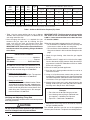
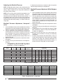
Table 1. Orifi ce or Drill Size for Propane (LP) Gases
Example:
• For a fl ow rate of 90 cubic feet gas per hour.
• Local heating value of the gas (obtained from
gas supplier) = 1,040 Btu per cubic foot.
• Input rate = 1,040 x 90 = 93,600 Btuh.
7. Adjustments to the fi ring rate can be made by adjusting
the gas manifold pressure.
The manifold pressure must be set to the appropriate
value for your installation. To adjust the manifold pressure,
Unit
Model
Number
Type
Gas
Fuel
Heating
Input
(Btuh)*
Gas
Valve
Manf.
Number
of
Burners
Orifi ce Size for Increased Elevation (Above Sea Level)
0 - 2,000 Ft 2,001 - 4,000 Ft 4,001 -6,000 Ft 6,001 - 8,000 Ft 8,001 - 10,000 Ft
R6GP-072*-100C L.P. 85,000 Honeywell 3 53 54 54 55 55
R6GP-072*-166C L.P. 141,000 Honeywell 5 53 54 54 55 55
R6GP-090*-200C L.P. 175,000 Honeywell 6 53 54 54 55 55
R6GP-090*-200C L.P. 175,000
White
Rodgers
651525252 53
R6GP-120*-235C L.P. 205,000
White
Rodgers
751525252 53
* Refer to Instructions for High Altitude Deration to determine heat-exchanger capacity at increased elevations.

5
remove the regulator cap and turn the adjusting screw
clockwise to increase pressure or counterclockwise to reduce
pressure. Replace the regulator cap after adjustments are
complete.
Reinstalling the Burner Manifold Assembly:
1. Carefully reinstall the gas manifold assembly to the
burner box with the four (4) fasteners removed earlier.
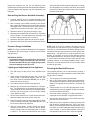
2. After installing the manifold assembly to the burner
box, inspect the alignment of the burners with the heat
exchanger tubes. The center of the burners should be
aligned with the center of the tubes. See Figure 2.
3. Reconnect the main gas piping to the gas valve.
4. Reconnect wiring to the gas valve terminals. Two White
wires to Stage-1 and one Brown wire to Stage-2 and
the black common wire to the "C" terminal.
5. Reconnect the spark ignitor wire to the spark ignitor.
6. Reconnect the fl ame sensor wire to the fl ame sensor.
Pressure Gauge Installation
NOTE: For LP gas installations. Refer to the unit rating plate
to determine the incoming gas maximum and minimum
inlet pressures.
IMPORTANT NOTES:
• If pressure testing the gas supply lines at pressures
greater than 1/2 psig (14 inches WC), the unit must
be disconnected from the gas supply piping system
to prevent damage to the gas valve.
Lighting and Adjustment of the Appliance
1. Turn ON the gas at the manual valve, outside of the
unit.
2. Check all gas connections for leaks with a soap and
water solution. If the solution bubbles, there is a gas
leak which must be corrected. DO NOT use an open
fl ame to check for gas leaks.
3. Turn ON the electrical power to the appliance.
4. Move the gas valve lever/switch/knob to the “ON” posi-
tion. The lever/knob must be moved to the end of its
range of motion to insure the valve is completely open.
Use only your hand to push in or turn the gas control
valve. Never use tools.
5. Set the room thermostat to a point above room tem-
perature to begin the heating cycle of the unit.
6. Check that the unit ignites and operates properly. Refer
to the installation instructions provided with your unit
for the normal operating sequence.
7. After the fl ame ignites, visually inspect the burner
assembly to ensure that the fl ame is drawn directly
into the center of the heat exchanger tube, as shown
in Figure 2. The end of the fl ame will be out of sight
around the bend of the heat exchanger tube. In a prop-
erly adjusted burner assembly, the fl ame color should
be blue with some light yellow streaks near the outer
portions of the fl ame.
Figure 2. Burner Inspection
NOTE: Until all of the air is bled out of the gas line, the
spark ignitor may not ignite the gas. If the ignition control
locks out, turn the thermostat to its lowest setting and wait
one minute then turn the thermostat to a point above room
temperature. The ignitor will try again to ignite the main
burners. This process may have to be repeated several
times before the burners will ignite. Once the burners are
lit, check all gas connections for leaks again with the soap
and water solution. If the solution bubbles, there is a gas
leak which must be corrected. Do not use an open fl ame
to check for gas leaks.
Checking the Manifold Pressure
The manifold pressure can be measured by installing a
pressure gauge or U-tube manometer to the outlet end of
the gas valve as follows:
1. Turn off gas prior to installing manometer.
2. With a 3/16” Allen wrench, remove the manifold pres-
sure tap plug located on the outlet side of the gas valve.
Refer to the appropriate manufactures instruction for
location.
3. A fi tting, which has a 1/8” NPT pipe thread that is com-
patible with the pressure gauge or U-tube manometer,
must be installed at this point.
4. Install the pressure gauge or U-tube manometer ac-
cording to the manufacturer’s supplied instructions.
5. Set the room thermostat to a point above room tem-
perature to start the furnace.
6. Allow the furnace to operate for three (3) minutes and
then check the manifold pressure. For LP gas instal-
lations, the manifold pressure should be factory set to
9.5” WC or to 10" WC dependent upon the style of gas
valve installed. If the manifold pressure is not set to
the appropriate pressure, then it must be adjusted.

6
Adjusting the Manifold Pressure
NOTE 1: Dependent upon the gas valve manufacturer, the
valve may come factory-set for a 9.5 or 10 in-WC manifold
setting. Always inspect the unit rating label to determine
the correct factory setting.
NOTE 2: The unit fi ring rate should be inspected for each
installation as described in these instructions. The mani-
fold pressure may be different then the factory setting. If
the determination of the actual unit fi ring rate cannot be
made with quality instruments, then the manifold pressure
should be set to the factory setting – as shown on the unit
rating label.
Manifold Pressure Adjustment, Honeywell
valve:
1. If the manifold pressure must be adjusted, then remove
the protective cap from the top of the High fi re gas valve
regulator as shown in the manufacturers instructions.
2. Turn the adjustment screw clockwise to increase the
manifold pressure and counter clockwise to decrease
the manifold pressure. Set the manifold pressure to the
factory settings, as shown on the unit rating label – or
to the correct manifold pressure setting to obtain the
correct fi ring rate.
3. Replace the protective cap over the adjustment screws
and tighten.
4. The low fi re, fi ring rate should be 65% of the high fi re,
fi ring rate
a. (From example 1: the furnace high fi re rating of
147,000 Btuh, would have a low fi re, fi ring rate of
95,550 Btuh. Or 0.65 x 147,000 Btuh.)
It should not be necessary to adjust the low fi re regulator
after the High fi re setting is accomplished.
Manifold Pressure Adjustment, White Rodgers
valve:
1. If the manifold pressure must be adjusted, then remove
the protective cap from the top of the High fi re gas valve
regulator as shown in the manufacturers instructions.
2. Turn the adjustment screw clockwise to increase the
manifold pressure and counter clockwise to decrease
the manifold pressure. Set the manifold pressure to the
factory settings, as shown on the unit rating label – or
to the correct manifold pressure setting to obtain the
correct fi ring rate.
3. Replace the protective cap over the adjustment screws
and tighten.
4. The low fi re, fi ring rate should be 60% of the high fi re,
fi ring rate
a. (From example 1: the furnace high fi re rating of 147,000
Btuh, would have a low fi re, fi ring rate of 88,200 Btuh.
Or 0.60 x 147,000 Btuh.)
Inspect the unit low fi ring rate in the same manner de-
scribed in the instructions for Verifying and Adjusting
Firing Rate.
5. Use the same procedure described above in steps 1-3
for the high fi re regulator to adjust the low fi re manifold
pressure. If the fi ring rate cannot be determined, set
the low fi re manifold pressure to the factory setting – as
shown on the unit rating label, or refer to table 3.
Table 2. Heating Rise/Range
Table 3. Unit/Valve data - LP gas only
MODEL
GAS
TYPE
HEATING
INPUT
HEATING
OUTPUT
HEATING RISE
RANGE (°F)
CFM RANGE
1,950 2,100 2,250 2,400 2,550 2,700 SCFM
R6GP-072*-100C Propane 85,000 68,000 15 -45 32 30 28 26 25 23
RISE (°F)
1,950 2,100 2,250 2,400 2,550 2,700 SCFM
R6GP-072*-166C Propane 141,000 112,800 35 - 65 54 50 46 44 41 39
RISE (°F)
2,425 2,625 2,800 3,000 3,188 3,375 SCFM
R6GP-090*-200C Propane 175,000 137,000 30 - 60 52 48 45 42 40 38
RISE (°F)
3,250 3,500 3,750 4,000 4,250 4,500 SCFM
R6GP-120*-235C Propane 205,000 164,000 25 - 55 47 43 40 38 36 34
RISE (°F)
* At elevations of 2,000 feet or less.
Unit Model Number Gas Valve Manf. Gas Valve Model
Maximum
Inlet Pres. †
Minimum
Inlet Pres. †
Factory Set, Manifold
Pres. † High Fire
Factory Set, Manifold
Pres. † Low Fire
R6GP-072*-100C Honeywell VR8205Q 14.0 (3.49) 11.0 (2.74) 10.0 (2.49) 4.0 (1.0)
R6GP-072*-166C Honeywell VR8205Q 14.0 (3.49) 11.0 (2.74) 10.0 (2.49) 4.0 (1.0)
R6GP-090*-200C Honeywell VR8205Q 14.0 (3.49) 11.0 (2.74) 10.0 (2.49) 4.0 (1.0)
R6GP-090*-200C White Rodgers 36H64 14.0 (3.49) 11.0 (2.74) 9.5 (2.37) 5.0 (1.24)
R6GP-120*-235C White Rodgers 36H65 14.0 (3.49) 11.0 (2.74) 9.5 (2.37) 5.0 (1.24)
† All Pressure values are expressed in: in-WC (kPa)

7
Removing the Pressure Gauge
U-tube Manometer
Once the manifold pressure has been properly adjusted,
the pressure gauge or U-tube manometer must be removed
from the gas valve.
1. Turn the thermostat to its lowest setting.
2. Turn OFF the main gas supply to the unit at the manual
shut-off valve, located outside of the unit.
3. Turn OFF all electrical supplies to the unit.
4. Remove the manometer adapter from the gas valve
and replace it with the 1/8” NPT manifold pressure plug
removed earlier. Ensure the plug is tightly sealed and
not cross threaded.
5. Turn ON all electrical power to the unit.
6. Turn ON the main gas supply to the unit at the manual
shut-off valve, located outside of the unit.
Completing the Conversion
1. For all R6GP/R4GN/R4GM Series conversions to LP gas,
affi x the conversion warning label (#703935) provided
in the kit to the outside of the units louvered burner ac-
cess panel. Next, affi x the conversion information label
(#710005) over the Natural Gas warning label. Each
label shall be prominent and visible after installation.
2. Affi x the gas valve manufactures labels to the valve as
described in the manufactures instructions.
3. Replace the unit's louvered burner access panel.
4. Run the appliance through a complete cycle to assure
proper operation.

¢709010c¤
7090100
7090100
Specifi cations and illustrations subject to change
without notice and without incurring obligations.
Printed in U.S.A. (07/09)
St. Louis, MO
-
 1
1
-
 2
2
-
 3
3
-
 4
4
-
 5
5
-
 6
6
-
 7
7
-
 8
8


Unbranded LP Conversion Kit, 920610 Installation guide
- Type
- Installation guide
Ask a question and I''ll find the answer in the document
Finding information in a document is now easier with AI
Related papers
-
Unbranded LP Conversion Kit, 920610 Installation guide
-
-
Broan FG7MQ Installation guide
-
-
Broan United States LP/High Altitude Natural Gas Conversion Kit Installation guide
-
-
-
Broan R8HE-A Installation guide
-
Broan LP Conversion Kit, USA Installation guide
-
Reznor R6GP Installation guide
Other documents
-
-
Mammoth Natural Gas, High-Altitude Conversion Kit Installation guide
-
Thermo Pride AOPS7749, AOPS7745 Owner's manual
-
Lennox LP Kit -- FOA (N, P) Unit Heater (40, 45, 60, 75, 100 & 125) TUA45S, 60S, 75S Separated Combustion Units 82M93 Installation guide
-
Thermo Pride AOPS7696 Owner's manual
-
Broan PPG2GF Installation guide
-
-
Reznor R6GN Installation guide
-
-