Krell Industries KCT User manual
- Category
- Recording Equipment
- Type
- User manual

KCT
Krell Current Tunnel
CAST Preamplifier
Instructions for Use
Owner’s Reference
THE LEADER IN AUDIO ENGINEERING

KCT
Krell Current Tunnel
CAST Preamplifier
v 01.0
Krell Industries, Inc.
45 Connair Road
Orange, CT 06477-3650 USA
TEL 203-799-9954
FAX 203-891-2028
E-MAIL [email protected]
WEBSITE http://www.krellonline.com
This product is manufactured in the United States of America. Krell ® is a registered trademark of Krell Industries, Inc., and is restricted for use by Krell
Industries, Inc., its subsidiaries, and authorized agents. Sustained Plateau Bias III™ is a trademark of Krell Industries, Inc. and is a Krell technology based
on U.S. Patent No. 5,331,291. CAST™, CAST II™, Krell Current Mode™, Krell Link™, and Theater Throughput™ are trademarks of Krell Industries, Inc.
All other trademarks and tradenames are registered to their respective companies.
© 2000 by Krell Industries, Inc. All rights reserved P/N 304373
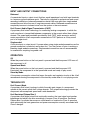
This product complies with the EMC directive (89/336/EEC) and the low-voltage directive (73/23/EEC).
WARNINGS
The preamplifier must be placed on a firm, level surface where it is not exposed to dripping or splashing.
The ventilation grids on the top of the preamplifier and the space underneath the preamplifier must be
unobstructed at all times during operation. Do not place flammable material above or beneath the preampli-
fier.
Before making connections to the preamplifier, ensure that the power is off and other components are in mute
or stand-by mode. Make sure all cable terminations are of the highest quality, free from frayed ends, short cir-
cuits, or cold solder joints.
Do not connect an RS-232 cable to the phono power port. Output from the phono power port could seriously
damage your computer. Do not connect the cable from a Krell KPE phono stage to the RS-232 port.
THERE ARE NO USER SERVICEABLE PARTS INSIDE THE PREAMPLIFIER
Please contact your authorized Krell dealer, distributor, or Krell if you have any questions not addressed in
this manual.

Krell Current Tunnel iii
Contents Page
INTRODUCTION 1
DEFINITION OF TERMS 1
REVOLUTIONARY KRELL CAST TECHNOLOGY 3
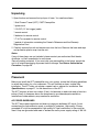
UNPACKING 5
PLACEMENT 5
AC Power Guidelines 5
QUICK START 6
FRONT PANEL DESCRIPTION 9
BACK PANEL DESCRIPTION 12
REMOTE CONTROL DESCRIPTION 15
Battery Installation and Removal 15
CONNECTING THE KCT PREAMPLIFIER TO YOUR SYSTEM 18
Input and Output Connections 18
KRELL LINK CONNECTIONS AND OPERATION 19
TAPE INPUT AND OUTPUT 20
OPERATING THE KCT PREAMPLIFIER 21
On/Off and Stand-by Operation 21
Main Zone and Zone 2 Operation 22
TROUBLESHOOTING SYSTEM NOISE 25
CUSTOMIZING THE KCT PREAMPLIFIER 26
Z1 and Z2 Balance 26
Input Name Menu 26
Input Level Trim 27
Input Balance Trim 27
Theater (Throughput) Mode 28
Brightness 29
Mute Menu 29
Output Trigger Setup 29
Tape Output Menu 30

iv Krell Current Tunnel
Contents, continued Page
AC Mains Menu 30
Program Remote Menu 31
Input Trigger Setup 31
Setup Memory 32
Krell Link 32
Trigger Delay Setup 33
Exit Menu 33
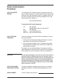
QUESTIONS AND ANSWERS 34
WARRANTY 35
RETURN AUTHORIZATION PROCEDURE 36
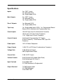
SPECIFICATIONS 37
List of Illustrations
Figure 1 The KCT Front Panel 8
Figure 2 The KCT Back Panel 11
Figure 3 The KCT Remote Control 14

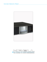
Krell Current Tunnel 1
Introduction
Thank you for your purchase of the Krell Current Tunnel (KCT) CAST Preamplifier. The
KCT features Krell Current Tunnel topology and Krell CAST technology, which work
together to reproduce music with unparalleled sound quality. The KCT has dual zone
capability for listening to music from different input devices at the same time, or listening
to one input device while recording another. Each zone has its own volume and balance
control.
Step-by-step menu options allow you to customize the KCT for ease of use and
seamless integration into your system. Remote control features include a handheld
remote control, which accesses all preamplifier functions as well as the compact disc
functions on Krell compact disc players. The KCT also features Krell Link, RS-232 and
12 VDC (12 Volt trigger) remote control inputs for a variety of system control options. A
menu-driven program remote option allows you to send KCT operating commands to a
learning or programmable remote control.
A front panel display provides feedback on input and zone status, menu function and
selection, and all preamplifier operations.
This owner’s reference manual contains important information on the placement,
installation, and operation of your KCT preamplifier. Please read this information
carefully. A thorough understanding of these details will help ensure satisfactory
operation and long life for your KCT and related system components.
Definition of Terms
Following are the definitions of key terms used in your owner’s reference manual.
CONFIGURATIONS
Krell Link
A method of synchronizing remote control operation for Krell systems that include
multiple preamplifiers, amplifiers, and associated components. When Krell Link in/out
connections are used, the remote capabilities of the linked components are controlled
from one component, called the control component. The linked components respond to
stand-by and operational mode commands from the control component via MIDI cables.
Theater Throughput
Theater Throughput is a Krell configuration option that allows the signal from a surround
preamp/processor to pass through a Krell preamplifier or integrated amplifier with no
gain, for integrated volume and balance management of Krell home theater systems.

2 Krell Current Tunnel
INPUT AND OUTPUT CONNECTIONS
Balanced
A symmetrical input or output circuit that has equal impedance from both input terminals
to a common ground reference point. The industry standard for professional and sound
recording installations, balanced connections have 6 dB more gain than single-ended
connections and allow the use of long interconnect cables. Balanced connections are
completely immune to induced noise from the system or the environment.
Krell Current Audio Signal Transmission (CAST)
A proprietary Krell circuit technology for connecting analog components, in which the
audio waveform is transmitted between components in the current rather than voltage
domain. The speed and bandwidth provided by Krell CAST yields accurate, realistic
music reproduction. Krell components connected via CAST perform as if they are all
part of a single circuit.
Single-ended
A two-wire input or output circuit. Use care when using single-ended connections as the
ground connection is made last and broken first. Turn the system off prior to making or
breaking single-ended connections. Single-ended connections are not recommended
for connections requiring long cable runs.
OPERATION
Off
When the power button on the front panel is pressed and the blue power LED turns off,
the component is off.
Operational Mode
When the power button on the front panel is pressed and the blue power LED
illuminates, the component is in the operational mode and ready to play music.
Stand-by Mode
A low power consumption status that keeps the audio and regulator circuits at idle. Krell
recommends leaving the component in the stand-by mode when it is not playing music.
TECHNOLOGY
Krell Current Mode
A proprietary Krell circuit topology in which the audio gain stages of a component
operate in the current rather than voltage domain. This unique technology provides the
component with exceptional speed and a wide bandwidth.
Krell Sustained Plateau Bias II
A proprietary Krell digital circuit that continually monitors the input signal and speaker
impedance and adjusts the bias accordingly to ensure Class A operation. Sustained
Plateau Bias II provides the enormous sonic benefits of continuous Class A operation
while minimizing the heat generation and power consumption normally associated with
Class A designs.

Krell Current Tunnel 3
Revolutionary Krell CAST Technology
Current Audio Signal Transmission, termed CAST, is a revolutionary method of
connecting analog audio components for unparalleled sonic performance. Innovative
engineering combines the new Krell CAST circuitry with existing Krell Current Mode
technology to create entire CAST systems that reproduce music with incredible range,
tonality, and precision.
Voltage Signal Transmission and the Traditional Audio System
Traditionally, signal is transmitted in the voltage domain between two components. In an
audio system, each component is a discrete entity with unique characteristics that act
upon the musical signal independently. Each component is unaware of the other
components in the system. The cables that connect the components also have their
own electrical characteristics, which affect the sonic presentation of the entire system.
CAST: A New Approach
CAST circuitry recognizes signal transmitted in the current domain instead of the
voltage domain between each component. CAST transmission unifies individual
components and their interconnects into an electrically linked whole. The sonic
presentation of the entire system remains intact.
CAST Basics
Here’s how a CAST audio system works. Internally, each CAST source transfers, or
amplifies, current using Krell Current Mode circuitry. This current signal is then output
using CAST circuitry. When the signal is received by a CAST input, Krell Current Mode
circuitry again takes over until the signal reaches the loudspeaker. By maintaining the
musical signal in the current domain from beginning to end, an entire CAST system
behaves as if it is one component. With CAST, anomalies of signal transmission
between components are eliminated. Cable impedances and their effects on the
transmitted signal are non-existent.
How CAST and Krell Current Mode Interact
While CAST is a new method of transferring the musical signal between components,
its origin stems from Krell Current Mode, the technology developed to transfer the
musical signal within a component. CAST combined with Krell Current Mode takes
circuitry signal transmission to the next evolutionary level. In essence, Krell Current
Mode maintains the integrity of the signal within the component and CAST preserves
the transmitted signal between components. Together, CAST and Krell Current Mode
technologies unify separate Krell components into a single global circuit.
CAST Cable Construction
A CAST system uses cables manufactured by Krell and other manufacturers specially
licensed by Krell. Thin and flexible CAST cables are constructed with the same build
quality as other Krell components and are aesthetically matched to the components that
Krell manufactures. An all-metal body and locking connectors with gold contacts are
part of the standard no-compromise specification developed for every CAST cable
made.

4 Krell Current Tunnel
The Best Musical Performance
When you operate a CAST system, you will hear significant improvements in every
performance area: speed, precision, dynamic range, depth and width of the sound
stage, transient impact, tonal balance, harmonic distortion, and more. The goal for
CAST is the same company goal used for all Krell products. Krell strives for the delivery
of the best performance of a musical event for you, using the full expression of
technology to date.

Krell Current Tunnel 5
Unpacking
1. Open the box and remove the top layer of foam. You see these items:
1 Krell Current Tunnel (KCT) CAST Preamplifier
1 power cord
1 12 VDC (12 Volt trigger) cable
1 remote control
2 batteries for remote control
1 T-10 Torx wrench for remote control
1 packet of information containing the Owner’s Reference and the Warranty
Registration Card
2. Carefully remove the unit and accessories from the box. Remove the foam end caps
and protective plastic wrap from the unit.
Notes
If any of these items are not included, please contact your authorized Krell dealer,
distributor, or Krell immediately for assistance.
Save all packing materials. If you must ship your preamplifier in the future, repack the
unit in its original packaging to prevent transit damage. See Return Authorization
Procedure, on page 36.
Placement
Before you install the KCT preamplifier into your system, review the following guidelines
to select the location for your component. This will facilitate a clean, trouble-free
installation. The KCT does not require a special rack or cabinet for installation. See
Specifications, on page 37, for the dimensions of the KCT.
The KCT requires at least two inches (5 cm) of clearance on each side and at least two
inches (5 cm) of clearance above the component to provide adequate ventilation.
Installations inside cabinetry may need extra ventilation.
AC POWER GUIDELINES
The KCT has superb regulation and does not require a dedicated AC circuit. Avoid
connections through extension cords or multiple AC adapters. High quality 15 amp
grounded AC strips are acceptable. High quality AC line conditioners or filters can be
used if they are grounded and meet or exceed the unit’s power supply rating of 100 VA.

6 Krell Current Tunnel
Quick Start
To access the full array of available features for the KCT preamplifier, please read the
entire owner’s reference manual. The abbreviated procedures in this Quick Start section
will allow you to connect and operate the KCT quickly and enjoy its basic features
before you read the entire manual. Numbers in parentheses refer to Figure 1 on page 8,
Figure 2 on page 11, and Figure 3 on page 14.
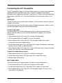
Connecting the KCT Preamplifier
1. Neatly organize the wiring between the KCT and all system components. Separate
AC wires from audio cables to prevent hum or other unwanted noise from being
introduced into the system.
2. Connect the CAST cables from the left and right Krell CAST 4-pin inputs (20) on the
KCT back panel to the CAST-equipped output of your source equipment. For
balanced or single-ended operation, connect the interconnect cables from either the
left and right balanced (17), single-ended (18) or tape (19) inputs to the balanced,
single-ended, or tape output of your source equipment.
Important
Connecting non-CAST components to CAST inputs or outputs can damage your
equipment and void your warranty. Do not attempt to alter CAST cable ends or CAST
inputs or outputs. It is electrically impossible to convert CAST input/output chassis
mount connectors for balanced or single-ended operation.
Please read the Warranty, on page 35, to understand the warranty limitations of the
KCT.
3. Connect the CAST (23), balanced or single-ended (22) main zone outputs on the
KCT back panel to your amplifier(s).
4. Connect the balanced (24) or single-ended (25) zone 2 outputs on the KCT back
panel to your amplifier(s).
5. To power on, connect the AC power cord to the IEC power connector (31), then plug
the AC power cord into the wall.
KRELL KCT appears in the front panel display (13),
indicating that the preamplifier is initializing. After initializing is complete, the KCT is in
the stand-by mode. The red stand-by LED (2) illuminates.
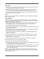
Operating the KCT Preamplifier
After the KCT is connected to your system and to AC power, you can begin operation.
Steps for basic operation follow:
IMPORTANT
Always mute or fully attenuate the preamplifier level when switching between active
sources (such as a CD player, tape monitor, or VCR).
Do not change the input connections to the preamplifier while the preamplifier is on.

Krell Current Tunnel 7
Use care when setting high playback levels. Always lower the volume level at the first
sign of loudspeaker distress.
1. With the KCT preamplifier in the stand-by mode (red stand-by LED [2] illuminated),
switch to the operational mode by pressing the front panel power button (1) or power
key (32) on the remote control. The blue power LED (3) illuminates and there is an
audible click. The KCT is ready for operation.
2. With the preamplifier output muted or the volume fully attenuated, select a source
manually through the front panel input select buttons (6) or through the input select
keys (39) on the remote control. Start playing the source. Use the level control knob
(14) or level keys (44) to set the volume to a comfortable listening level.
Note
The KCT automatically plays through the main zone until you select zone 2 operation.
3. To return the KCT to the stand-by mode, press the power button (1) or power
key (32).
Krell recommends leaving the KCT in the stand-by mode when it is not playing music.
If you wish to turn your system off:
Turn your system off if it will not be used for a long period of time.
1. Place the amplifiers in the stand-by mode.
2. Press the power button (1) or power key (32) to switch the KCT to the stand-by
mode.
3. Turn off the amplifiers using the back panel power switch or by disconnecting them
from AC power.
4. Disconnect the KCT from AC power by unplugging the AC power cord from the wall.

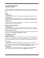
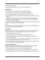
Figure 1 The KCT Front Panel
Power
1 Power Button
2 Stand-by LED
3 Power LED
Remote Control Functions
4 Infrared Sensor
5 Infrared Transmitter LED
1
Preamplifier Functions
6 Input Select Buttons
7 Tape Button
8 Mute Button
9 Phase Button
10 Zone Button
11 Main Zone LED
12 Zone 2 LED
Display
13 Front Panel Display
Level Control
14 Level Control Knob
Menu Functions
15 Menu Button
16 Enter Button
69 13 14
1
4 527
3
10
11
12
16
15
8
KCT
CLASS A

Krell Current Tunnel 9
Front Panel Description
See Figure 1 on page 8
The KCT preamplifier front panel provides power on, input and zone selection, level
control, menu functions, and status display. Front panel features and their descriptions
follow.
Power
1 Power Button
Use this button to switch the KCT between the stand-by and the operational modes.
2 Stand-by LED
The red stand-by LED illuminates when the KCT is plugged into a standard AC wall
receptacle, indicating that the KCT is ready to be switched to the operational mode.
3 Power LED
The blue power LED illuminates when the KCT is in the operational mode and flashes
when remote control signals are received.
Remote Control Functions
4 Infrared Sensor
The infrared sensor receives commands from the KCT remote control. For proper
remote control operation, make sure the infrared sensor is not covered or obstructed.
5 Infrared Transmitter LED
The infrared transmitter LED flashes when the KCT sends infrared signals to another
remote control. See Program Remote Menu, on page 31.
Preamplifier Functions
6 Input Select Buttons
Use these buttons to select the corresponding rear panel input that is connected to a
CAST (C-1, C-2), balanced (B-1, B-2), or single-ended (S-1, S-2, S-3) analog source.
The front panel display (13) shows the active zone, the selected input, and volume
level.
7 Tape Button
Use this button to select the corresponding rear panel input that is connected to a
analog tape source. When
TAPE is activated, the front panel display (13) shows the zone
that is the pathway for the tape output. See Tape Output Menu, on page 30.
8 Mute Button
Use this button to mute the preamplifier output. To unmute, press the mute button
again. To customize mute button operation, see Mute Menu, on page 29.

10 Krell Current Tunnel
9 Phase Button
Use this key to invert the absolute polarity of the variable output 180 degrees for the
selected input. The front panel display (13) shows
INVERT for the negative phase; the
display remains blank for the positive phase.
10 Zone Button
Use this button to select the main zone (the main listening or viewing area) or zone 2
(another listening area).
11 Main Zone LED
The red main zone LED illuminates when the main zone is activated. Zone status is also
shown in the front panel display (13).
12 Zone 2 LED
The green zone 2 LED illuminates when zone 2 is activated. Zone status is also shown
in the front panel display (13).
Display
13 Front Panel Display
The front panel display provides preamplifier status messages, including input and zone
selection, tape output status, volume and balance level, and menu selections.
Level Control
14 Level Control Knob
Use this knob to increase or decrease system volume level or, with the balance key, to
adjust balance. The level control knob is also used to select menu options to customize
the KCT. See Customizing the KCT Preamplifier, on page 26.
Menu Functions
15 Menu Button
Use the menu button to access menu options for customizing the KCT. The front panel
display shows
MAIN MENU and submenu name. See Customizing the KCT
Preamplifier, on page 26.
16 Enter Button
Use this key to access submenu selections.

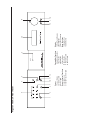
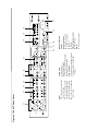
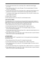
Figure 2 The KCT Back Panel
Inputs
17 B-1 and B-2 Left and Right
Balanced Inputs
18 S-1, S-2, and S-3 Left and
Right Single-ended Inputs
19 Tape Left and Right Inputs
20 C-1 and C-2 Left and Right
CAST Inputs
Tape Output
21 Tape Output
Main (Zone) Outputs
22 Preamp Left and Right Outputs
23 CAST Preamp Outputs
Zone 2 Outputs
24 Balanced Left and Right Outputs
25 Single-ended Left and Right
Outputs
Back Panel Remote
Control
Inputs and Outputs
26 Krell Link In and Out
27 12 VDC In and Out
28 RC-5 In
29 RS-232
Phono Stage Connector
30 Phono Power
Power
31 IEC Power Connector
17 20 21 22 23 26 28 271918
30
29 31
24
25

12 Krell Current Tunnel
Back Panel Description
See Figure 2 on page 11
The KCT preamplifier back panel provides all input and output connections, remote
control inputs and outputs, and power connection. Back panel features and their
descriptions follow.
Inputs
17 B-1 and B-2 Left and Right Balanced Inputs
The KCT is equipped with two pairs of balanced analog source inputs with XLR
connectors.
18 S-1, S-2, and S-3 Left and Right Single-ended Inputs
The KCT is equipped with three pairs of single-ended analog source inputs with RCA
connectors.
19 Tape Left and Right Inputs
The KCT is equipped with one pair of single-ended tape source inputs with RCA
connectors.
20 C-1 and C-2 Left and Right CAST Inputs
The KCT is equipped with two pairs of CAST inputs with 4-pin bayonet connectors, for
use with Krell CAST-equipped input devices.
Tape Output
21 Tape Left and Right Outputs
The KCT is equipped with one pair of tape outputs with RCA connectors.
Main (Zone) Outputs
The following outputs are for the main zone.
22 Preamp Left and Right Outputs
The KCT is equipped with two pairs of preamplifier outputs: one pair of balanced
outputs with XLR connectors and one pair of single-ended outputs with RCA
connectors.
23 CAST Preamp Outputs
The KCT is equipped with two pairs of CAST preamplifier outputs with 4-pin bayonet
connectors, for use with Krell CAST-equipped amplifiers.
Zone 2 Outputs
The following outputs are for zone 2.
24 Balanced Left and Right Outputs
The KCT is equipped with one pair of balanced outputs with XLR connectors.

Krell Current Tunnel 13
25 Single-ended Left and Right Outputs
The KCT is equipped with one pair of single-ended outputs with RCA connectors.
Back Panel Remote Connections
26 Krell Link In and Out
The KCT is equipped with a Krell Link communications input and output data port. Krell
Link allows synchronized remote power on and off of other components connected with
Krell Link. See Krell Link Connections and Operation, on page 19.
27 12 VDC In and Out
The KCT is equipped with three outputs that send and one input that receives 12 VDC
power on/off (12 V trigger) signals to and from other Krell components and other
devices that incorporate a 12 V trigger. This allows you to turn other components on or
off, or to and from stand-by, through the remote control. When the KCT is switched to
the operational mode and is connected to other components through the 12 V trigger, it
sends a signal that will switch other components, allowing whole systems or parts of
systems to be easily coordinated.
Notes
The 12 VDC output power is limited to 30 ma.
Consult the owner’s reference manual of the components used in a custom installation
to take full advantage of the remote capabilities of the KCT.
28 RC-5 In
The KCT is equipped with an RC-5 input that makes custom installation easy and
secure by accepting baseband RC-5 input commands from hardwired remote
controllers.
29 RS-232
The KCT is equipped with an RS-232 port that receives messages from a computer-
based control system, providing integrated control of all preamplifier functions. See the
KCT developer’s reference, “RS-232 Port: Sending Commands and Interpreting Data,”
for more information.
Phono Stage Connector
30 Phono Power
The KCT is equipped with a phono power port, for connecting the KCT with a Krell KPE
phono stage.
Power
31 IEC Power Connector
The IEC power connector is for use with the provided IEC standard 15 amp AC power
cord.

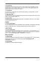
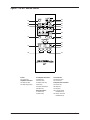
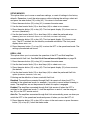
Figure 3 The KCT Remote Control
32
35
43
45
48
36
34
38
39
40
42
47
49
33
37
41
46
44
Preamplifier Functions
35 Mute Key
36 Phase Key
37 Main Zone Key
38 Z2 Key
39 Input Select Keys
40 Tape Key
Menu Functions
41 Menu Key
42 Enter Key
Level Control
43 Bal(ance) Key
44 Level Keys
Compact Disc Functions
45 Pause Key
46 Stop Key
47 Play Key
48 Track Forward
and Back Keys
49 Search Forward
and Back Keys
Power
32 Power Key
Amplifier Functions
33 Amp Pwr Key
34 Amp Sel(ect) Key
14 Krell Current Tunnel

Krell Current Tunnel 15
Remote Control Description
See Figure 3 on page 14
BATTERY INSTALLATION AND REMOVAL
The KCT remote control uses two AAA-size 1.5 Volt batteries. Batteries are included
with the shipment. To install the batteries:
1. Remove the remote control backplate, using the supplied T-10 Torx wrench.
2. Install the batteries, following the battery position diagram on the plastic battery
receptacle.
3. Replace and secure the backplate.
Replace batteries when remote control function becomes intermittent.
Remove batteries if the remote control is not used for a long period of time. Battery
leakage can damage the remote control.
The remote control provides power on, input and zone selections, level and balance
control, menu, and compact disc functions. Remote control keys and their descriptions
follow.
Power
32 Power Key
Use this key to switch the KCT between the stand-by and the operational modes.
Amplifier Functions
33 Amp Pwr Key
Use this key to activate Krell amplifiers connected to your system. The amp pwr key
also activates the control component for amplifiers connected by Krell Link.
34 Amp Sel(ect) Key
Use this key to switch between CAST and balanced inputs on a Krell Full Power
Balanced amplifier connected to your system. The red center LED illuminates when the
CAST output is active.
Preamplifier Functions
35 Mute Key
Use this key to mute the preamplifier output. To unmute, press the mute key again. To
customize mute key operation, see Mute Menu, on page 29.
36 Phase Key
Use this key to invert the absolute polarity of the variable output 180 degrees for the
selected input. The front panel display (13) shows INVERT for the negative phase; the
display remains blank for the positive phase.

16 Krell Current Tunnel
37 Main Zone Key
Use this key to select the main zone (the main listening or viewing area). The red main
zone LED (11) on the front panel illuminates when the main zone is activated.
38 Z2 Key
Use this key to select zone 2. The green zone 2 LED (12) illuminates when zone 2 is
activated.
Note
Both zones can play simultaneously.
39 Input Select Keys
Use these keys to select the corresponding rear panel input that is connected to a
CAST (C-1, C-2), balanced (B-1, B-2), or single-ended (S-1, S-2, S-3) analog source.
The front panel display (13) shows the selected input, the active zone, and volume
level.
40 Tape Key
Use this key to select the corresponding rear panel input that is connected to a tape
analog source. When TAPE is activated, the front panel display (13) shows the zone that
is the pathway for the tape output. See Tape Output Menu, on page 30.
Menu Functions
41 Menu Key
Use this key to access the menu options for customizing the KCT. The front panel
display (13) shows
MAIN MENU and submenu name. See Customizing the KCT
Preamplifier, on page 26.
42 Enter Key
Use this key to access submenu selections.
Level Control
43 Bal(ance) Key
Use this key, along with level keys (44) or level knob (14) on the front panel, to balance
output levels. The front panel display (13) shows balance status for three seconds.
44 Level Keys
Use these keys to increase or decrease system volume level or, with the balance key
(43), to adjust balance. The level keys are also used to select menu options to
customize the KCT. See Customizing the KCT Preamplifier, on page 26.
Page is loading ...
Page is loading ...
Page is loading ...
Page is loading ...
Page is loading ...
Page is loading ...
Page is loading ...
Page is loading ...
Page is loading ...
Page is loading ...
Page is loading ...
Page is loading ...
Page is loading ...
Page is loading ...
Page is loading ...
Page is loading ...
Page is loading ...
Page is loading ...
Page is loading ...
Page is loading ...
Page is loading ...
Page is loading ...
Page is loading ...
Page is loading ...
-
 1
1
-
 2
2
-
 3
3
-
 4
4
-
 5
5
-
 6
6
-
 7
7
-
 8
8
-
 9
9
-
 10
10
-
 11
11
-
 12
12
-
 13
13
-
 14
14
-
 15
15
-
 16
16
-
 17
17
-
 18
18
-
 19
19
-
 20
20
-
 21
21
-
 22
22
-
 23
23
-
 24
24
-
 25
25
-
 26
26
-
 27
27
-
 28
28
-
 29
29
-
 30
30
-
 31
31
-
 32
32
-
 33
33
-
 34
34
-
 35
35
-
 36
36
-
 37
37
-
 38
38
-
 39
39
-
 40
40
-
 41
41
-
 42
42
-
 43
43
-
 44
44


Krell Industries KCT User manual
- Category
- Recording Equipment
- Type
- User manual
Ask a question and I''ll find the answer in the document
Finding information in a document is now easier with AI
Related papers
-
 Krell Industries Link Controller Owner’s Reference
-
 Krell Industries DVD Standard Owner’s Reference
-
 Krell Industries S1500 User manual
-
 Krell Industries S1500 User manual
-
 Krell Industries Phantom II Quick start guide
-
 Krell Industries Evolution Two WCES 2005 User manual
-
 Krell Industries Theater 7 XD Installation guide
-
 Krell Industries Phantom Quick start guide
-
 Krell Industries 350Mcx Instructions For Use Manual
-
 Krell Industries Connect Stream Player Owner’s Reference


Other documents
-
 Pass Labs XP-20 User manual
-
 Pass Laboratories XP-10 Owner's manual
-
 fezz SAGITA User manual
-
Harman Mark Levinson No526/No523 Dual-Monaural Preamplifier User manual
-
 Plinius Kaitaki Preamplifier User manual
-
 Dan D'Agostino PROGRESSION PREAMPLIFIER Owner's manual
-
 VTL TL6.5 Owner's manual
-
Bel Canto PRe1 User guide
-
Audio Research Reference 3 Owner's manual
-
Kenwood TK-760G User manual


